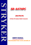
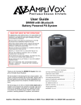
1
10-8 In-Car Video System
Installation / User Manual
2011r1
Warranty & Return Information
All Products
• Three (3) year free replacement of any failed component. No RMA
required.
Car Camera Components
1. Call 1-888-788-1048 and ask for Technical Support.
2. We will then mail a new component via USPS Priority Mail within
one (1) business day.
3. When you receive the replacement, mail back the failed component.
Shipping Address
Copyright © 2011 10-8 Video Digital Evidence Solutions. • All rights reserved.
Disclaimer: 10-8 Video Digital Evidence Solutions reserves the right to make changes in
specifications at any time and without notice. The information provided by this document
is believed to be accurate and reliable. However, no responsibility is assumed by 10-8 Video
Digital Evidence Solutions for its use; nor any infringements of patents or other rights of
third parties resulting from its use. No license is granted under any patents or patent rights
of 10-8 Video Digital Evidence Solutions.
Other company and product names mentioned herein may be trademarks of their respective
companies.
10-8 Video Digital Evidence Solutions
301 Market Street. E. #F
Fayetteville, TN 37334
Phone Numbers
(888) 788-1048 • (931) 262-2221
(931) 233-1263 (FAX)
10-8 Digital Video Evidence Solutions
301 Market Street. E. #F
Fayetteville, TN 37334
Tel: (888) 788-1048 • (931) 262-2221
Fax: (931) 233-1263
World Wide Web: www.10-8Video.com
2
3
Contents
CD-ROM Instructions
Manuals
Safety
9
9
10
Daily Operation
10
Package Contents
12
System Schematic
14
Hardware: Installation
15
Introduction
Digital Video Recorder Unit (DVR)
Common Installation Areas
Emergency Lights & Manual Activation
2.4GHZ Wireless Mic
Brown Wire (Trigger REC)
Trigger REC DVR Set-up
Black Wire (Audio Out)
2.4GHZ Mic Antenna
UHF Wireless Mic
Single System Setup
Automatic Frequency Selection
Automatic Transmitter Setup
PGX1 Bodypack Transmitter
Wearing the Bodypack Transmitter
Changing the Bodypack Transmitter Batteries
Mirror Monitor
Camera Mount
Front Camera
Rear Camera
G-Force Sensor
4
15
16
16
18
20
20
21
21
23
24
26
26
27
28
29
29
30
32
34
36
37
GPS System
Setting the GPS Speed Trigger
37
37
Hardware: Configuration
38
DVR Configuration
Entering Your Unit ID
Setting Date and Time
G-Force Sensor Configuration
38
39
40
41
Hardware: Usage
42
In-Car Playback
Watch Previously Recorded Events
Viewing Today’s Recordings
Viewing Another Day’s Recordings
Stopping Playback
DVR Remote Control
Entering Your Unit/Car ID
Camera Adjustment
Wireless Mic – 2.4GHZ
Syncing Transmitter and Cradle
Transmitting Audio
Mode Button
Microphone
Wireless Mic - UHF
42
42
42
43
43
44
44
45
46
46
46
47
47
48
Software: Installation
49
Software Installation
49
Software: Introduction
50
Software Overview
50
Software: Usage
52
Opening A File
52
5
Contents
Searching For A File
Playing A File
Adjusting Playback Speed
Adjusting Playback Volume
Maximizing the View of a Video Clip
Stopping Playback
Monitoring G-Force and Speed Events
Using the Google™ GPS Window
Saving a Snapshot
Exporting Events to a Video File
Maintaining Evidence Integrity
Exported File Format
Steps to Export
Video Export Options
Exporting an Event Report
Software Settings
System Parameters
Map Parameters
Video Parameters
File Associations
Archiving Video Tips
Appendix A
GMT Time Zones - United States
6
Contents
53
54
54
54
54
55
55
56
56
57
57
57
57
57
59
60
60
60
60
61
62
This page left intentionally blank.
64
64
Contents
7
CD-ROM
CD-ROM Instructions
The CD at left contains the viewer software needed for playback on your
computer. It also includes PDF copies of all manuals.
When you insert the CD it will automatically run the software
installation program
Manuals
To access the manuals:
1
2
CD-ROM
8
3
Insert the CD into your CD-ROM/DVD drive.
When the installation program launches, click Cancel at the install
prompt.
You can then access the files on the CD through your file manager like
you would any other CD.
9
Safety
Daily Operation
You, as the driver, are solely responsible for the safe operation of your
vehicle and the safety of your passengers according to the US and local
traffic regulations.
WARNING: Do not use any features of this system to the
extent it distracts you from safe driving. Your first priority
while driving should always be the safe operation of your
vehicle.
10-8 Video cannot accept any responsibility whatsoever for accidents
resulting from failure to observe these precautions or safety instructions:
WARNING: This product utilizes high voltage. Any
unauthorized modifications or damage to the products may
result in electrical shock.
1. Handle all components with care. Inspect regularly for damage to
components and cabling.
Excessive force used before, during or after installation that
results in a damaged or non-functional part shall void all
warranties.
Improper installation or modification of this product shall void all
warranties.
2. You are responsible to ensure that the installation of this product does not void or affect the vehicle manufacturer’s warranty.
10-8 Video, or its branches are not liable in full or in part for
improper installation resulting in loss or damage to your property,
or for voiding all or part of the vehicle manufacturer’s warranty.
3. Do not apply excessive force to any of the components contained
within this kit.
4. Please follow the procedures from this installation manual.
10
11
Package Contents
HARNESSES (Simplified for clairity)
Power Harness
A/V Harness
Sensor Harness
2.4GHZ Harness
Mirror Harness
Video Harness
2
REC ALM SD1
IR
PWR GPS SD2
Camera* & Mount
Mirror
Digital Video Recorder (DVR)
Wireless Mic (Optional)
2.4GHZ model shown.
Camera Harness
GPS Unit (Optional)
* NOTE: Actual camera appearance may vary from illustration.
12
13
System Schematic
Hardware: Installation
Introduction
The installation of the 10-8 Patrol Car video system breaks down to some
very simple steps. The basic connection for video and audio are very similar
to a VCR or DVD player. The one area that differs from what you may have
done in the past is the connections for the alarm inputs . There are four (4)
sensor wires that will activate the recorder anytime voltage is applied to any
of the four (4) wires.
GPS
6 Pin
Power
Harness
To help make the connections easier, the cables that attach to the back of
the DVR each use a different type of connector. Familiarize yourself with
the inputs in the picture on pages 10 and 11.
4 Pin
A/V
Harness
You will need a single 12 volt power source for the system with
just one (1) power and one (1) ground source needed.
RED:
Vehicle +12V “Ignition on”
BLACK:
Vehicle Chassis Ground
BLACK (PWR GND)
to ground
RED (PWR)
to +12V
Sensor 2 Out
Sensor 3 In
Sensor 4 In
Sensor 1 Out
Trigger Wire (Trigger REC) - Brown
Sensor 1 In
Sensor 2 In
GPS
Fuse
We strongly recommend that the power source be from switched power
that is only hot when the vehicle key is in the ‘ON’ position. This should be
a five (5) amp fused power source. To eliminate interference, there should
be no other equipment on this circuit.
It is also very important that the ground be a good chassis
ground source and not tied into the ground of other equipment.
When the DVR’s door is unlocked to allow access to the SD
cards the system is automatically powered down to protect the
files on the SD cards. When the door is locked, the DVR system
will be able to accept power and turn on again.
CAT 5
NOTE: Actual camera appearance may vary from illustration.
14
15
Hardware: Installation
Digital Video Recorder Unit (DVR)
The first thing you will want to do is locate where you want to install the
DVR. The small size of the unit makes that much easier than just a few short
years ago. Common Installation Areas
• Main equipment console
• Either side of the console
GPS
• In the dash
• Under the dash.
Try to keep the unit in sight of the driver where they will be able
to use the I/R remote more easily. If needed, the DVR ships with
brackets for mounting.
1
Insert the Red/Black 6-pin Power Harness Connector into power
receptacle in rear of DVR unit making sure it locks into place.
2
3
4
5
6
7
Connect BLACK lead to a chassis ground.
Connect RED lead to 12 volt ‘ignition on’ power source.
Connect Sensor Harness to back of DVR.
Connect 4-pin A/V Harness to back of DVR.
6 Pin
Power Harness
1
4 Pin
AV Harness
Sensor
Harness
5
6
4
RED: Vehicle +12 v “Ignition on”
GPS
Camera
Harness
7
GPS
BLACK: Vehicle Chassis Ground
FIG. 1
Connecting Harnesses to DVR
Connect GPS Cable Connector to back of DVR.
Connect Camera Harness to back of DVR. Tighten connector nut to
secure harness.
16
DVR Installation
17
Hardware: Installation
Emergency Lights & Manual Activation
There are four (4) wires (leads) coming from the sensor harness. Each wire
will activate the recorder when voltage is applied to any single wire. In a
typical patrol car installation, 2 of these wires will be used.
These wires will detect when voltage is present and activate the
recorder.
Sensor Wire 1
1
Connect one wire to the output side of your control box for your
pursuit lights.
You can connect it to any of the lights that are used for emergency
traffic. This way the recorder will start anytime you are running
emergency traffic. Depending on the type of switch box used, there
may be a place to connect at the back of the switch box. If not, simply
connect to any wire that goes to a 12v light that is activated when you
turn on the emergency/pursuit lights. Sensor Wire 2
2
Caution: These wires are very sensitive and care must be
taken that you do not connect to a wire that has low voltage all
the time, as the recorder will detect voltage and activate the
recorder.
Connect the second wire to a manual switch that you will activate
when you want to start the recorder without lights activated.
Sensor 3 - to brown wire of 2.4Ghz Mic
Sensor 2 - to manual switch
Sensor 1 - to pursuit lights
FIG. 2
Sensor Harness
You can use any switch of your choosing that will provide 12v to the
wire.
Many control boxes in use today will have a blank switch that is not
being used. These are a great choice for the manual switch. If none are
available, a simple toggle or rocker switch mounted in a convenient
location works well.
18
Emergency Lights & Manual Activation Installation
19
Hardware: Installation
2.4GHZ Wireless Mic
If your department opted for our new 2.4ghz wireless microphone system,
congratulations! This is an incredible wireless microphone with excellent
range and clarity. The installation is easy and straight forward.
1
Find a suitable place in the vehicle for the base station/receiver.
A bracket is included. It should be mounted in an easily accessible
position. Be sure there is room to easily insert and remove the
transmitter in the cradle.
2
3
Connect the RED wire (labeled PWR) to a positive 12v source.
Connect the BLACK wire (labeled PWR GND) to a ground.
All of the wires are labeled from the factory. For this installation,
there are 3 wires that will not be used for this installation:
•
•
•
a white wire labeled ‘Mute Indication’
a black wire labeled ‘Trigger Gnd’
an orange wire labeled ‘ TX indication’.
These wire can be cut or tucked away.
Brown Wire (Trigger REC)
One wire’s use is optional; the small brown wire labeled ‘ Trigger REC’. If
this wire is connected to the Sensor #3 lead from the back of the DVR (FIG 2), then the DVR will begin recording when the talk button on
transmitter is active and lit.
In other words, if an officer keeps their mic on stand-by when not in use,
then when they activate with the ‘talk’ button to begin transmitting it will
activate the recorder. This is useful when outside the car and not recording,
and then a situation comes up and the officer needs to activate the recorder
remotely to begin recording. This is only optional and should be left up to
the department or officer of the vehicle.
20
If you hooked up the brown trigger lead to the DVR for remote activation,
there is one setting that needs changed in the DVR: Trigger REC DVR Set-up
1
2
3
4
5
6
7
8
9
Power on the system.
Press the ‘Login’ key on the remote.
Use the arrow keys to select ‘Vehicle’.
Select ‘Sensor’.
On the next screen on the 3rd Sensor line, Under Enable, change to
‘ON’
Change Pwr to ‘Low’.
Change Rec to ‘ON’.
Change Alarm to ‘ON’.
Scroll down to ‘Save’ and select to save the changes.
Black Wire (Audio Out)
1
Plug the male RCA plug into the female red RCA plug coming from
the camera wire harness. (FIG 3)
2.4GHZ Wireless Mic Installation
21
CAM PWR
to DVR CAM1
2.4GHZ Mic Antenna
1
2
3
Plug the antenna into the gold plug on the top of the cradle.
Secure by tightening the lock nut.
Run the wire down under the dash or other hidden location,
somewhere toward the front of the vehicle.
Velcro or double-sided tape works great for securing the
antennae end to a flat surface on the vehicle.
Audio Out
male RCA
female RCA
Fuse
Trigger Wire (Trigger REC) - Brown
RED (PWR) to +12V
Sensor 2 Out
BLACK (PWR GND) to ground
Sensor 3 In
Sensor 4 In
Sensor 1 Out
Sensor 1 In - (Brown)
Sensor 2 In
CAM signal
Hardware: Installation
CAT 5
FIG. 3
2.4GHZ Wireless Mic Installation
22
2.4GHZ Wireless Mic Installation
2.4GHZ Wireless Mic Installation
23
Hardware: Installation
UHF Wireless Mic
1 Locate a convenient spot for the wireless mic receiver (the small box
with the collapsible antennas).
The location does not have to be readily accessible once it is
installed so you may want to put it under a seat, or under the
dash Since it is so small and light, just Velcro it to the firewall or
anywhere else that is convenient for you.
1
It is recommended that it be in the front half of the vehicle for the
best reception.
2
3
2
Plug in the power lead to one of the available power leads on the DVR
power harness.
3
Locate the audio cable - the black cable in your kit that has a male
phono plug on one end and red RCA on the other.
4
Plug the phono plug into the 1/4” unbalanced output jack on the back
of the wireless receiver (#4 - FIG 5).
5
6
Mount the wireless receiver.
Audio LED
Indicates strength of incoming
audio signal: green = Normal,
amber = Strong, red = Peak.
LED screen
See “Single System Setup” page 24.
Channel Button
See “Single System Setup” page 24.
4
5
6
Ready LED
Green light indicates system is ready
for use.
Infrared (IR) Port
Broadcasts IR signal to transmitter.
Sync Button
Press to synchronize transmitter and
reciever frequencies.
FIG. 4
UHF Wireless Receiver - FRONT
Plug the RCA plug end of the audio cable into the red RCA plug of the
Audio/Video input cable from the back of the DVR.
Be sure to read the wireless mic section on syncing the
transmitter and receiver. If installing systems in more than one
vehicle, set the frequencies two to four channels apart to allow
more than one system in the same area without interference.
24
1
2
AC Adapter Jack
Adapter Cord Tie-off
3
4
XLR Balanced Mic Output Jack
(not used)
1/4” Unbalanced Output Jack
FIG. 5
UHF Wireless Receiver - BACK
UHF Wireless Mic Installation
25
Hardware: Installation
Single System Setup
Automatic Transmitter Setup
In any wireless setup, each transmitter and receiver pair must be tuned
to the same frequency, or channel. The 10-8 wireless system uses automatic
transmitter setup to synchronize the transmitter and receiver channels.
1
2
Turn ON the transmitter.
3
4
Expose the transmitter IR port to the receiver. (FIG. 7)
Automatic Frequency Selection
1
Press and release the channel button. (FIG. 6)
This scans for a clear channel and sets the receiver to that
channel.
LED screen displays
Press channel button to scan
current channel
for a clear channel
System
scans for
clearest
available
channel
FIG. 6
Frequency Selection
2
Proceed to Automatic Transmitter Setup on the next page.
26
UHF Wireless Mic Installation
5
6
Open the transmitter battery compartment to display the infrared (IR)
port. (See page 28)
Press and hold the sync button on the receiver until the red light stops
flashing on both the receiver and transmitter. (FIG. 7)
FIG. 7
Syncing the Transmitter and Receiver
When the receiver’s ready light glows, the system is ready for use.
Close the transmitter’s battery compartment.
UHF Wireless Mic Installation
27
Hardware: Installation
PGX1 Bodypack Transmitter
Wearing the Bodypack Transmitter
Clip the transmitter to a belt 1 or slide
through the transmitter clip 2 as shown. If
using a belt, slide the transmitter until the
belt is pressed against the base of the clip.
Changing the Bodypack Transmitter Batteries
•Expected life for alkaline batteries is
approximately eight (8) hours.
•When the transmitter light glows red,
the batteries should be replaced
immediately, as illustrated.
FIG. 8
1
Power / Infrared (IR) / Mute Indicator
Color & State
Meaning
Amber, Solid
Mute on.
Green, Solid
Ready.
Green, Flashing
Red, Solid
Red, Flashing
Red, Pulsing on startup
Red, Pulsing after Sync.
Controls locked.
Battery power low. (Transmitter cannot be turned off until
batteries are changed)
IR transmission in process.
Batteries dead. (Transmitter cannot be turned on until batteries are changed)
Transmitter and receiver are incompatible; contact 10-8
Video
2
On-Off / Mute Switch
Press and hold to turn on or off. Press and Release to mute or un-mute.
3
4-Pin Microphone Input Jack
4
Infrared (IR) Port
Receives infrared beam to synchronize frequencies. When using multiple systems,
only one transmitter IR port should be exposed at a time.
5
Gain Adjustment Switch
28
UHF Wireless Mic Installation
UHF Wireless Mic Installation
29
Hardware: Installation
Mirror Monitor
1 Mount the mirror/monitor over the existing mirror.
2 Run wires to DVR.
4 Pin A/V
Harness (to DVR)
A good place to run the wires for the mirror is to tuck them in the
front edge of the headliner and down the passenger side pillar
post. The covers on most modern pillar posts snap in to place
and are easily removed with plenty of room.
3
Run the wires down along the door edge and under the glove box to
the location of the DVR.
4
Connect the power lead to one of the available power leads on the DVR
power harness.
5
Plug the yellow RCA connector labeled ‘Video1’ to the yellow RCA
female connection of the 2 leads coming from the A/V Output port.
Yellow RCA
(Female)
Yellow RCA
(Male)
Power
(Male)
Power
(Female)
Video
(Female)
Video
(Male)
The red audio out is generally not used as audio playback is
not usually needed in the vehicle. If you wish to use the audio
out, you will need to connect to a powered speaker with volume
control.
FIG. 9
Mirror Installation
30
Mirror Installation
31
Hardware: Installation
Camera Mount
The mount is an excellent commercial mount and is very strong when
properly attached to the windshield. 1
1
Locate the mounting location of the camera - high and just right of
center on the windshield.
Press in button.
This is normally to the rear and slightly to the right of the rear
view mirror/monitor.
Leave just enough room for the camera to rotate 180 degrees in
either direction.
2
3
2
Pull lever over
button.
Clean the glass where the mount is to be placed.
Press in on the center button of the mount and pull the locking lever
up and over the center button to lock it in place.
3
Locked position.
32
Camera Mount Installation
33
Hardware: Installation
Front Camera
1 Run the included cable along side the mirror/monitor cable to the DVR.
2 Plug the BNC video connector from the camera to the BNC video-in
cable from the DVR.
3
Connect the power lead to one of the available power leads on the DVR
power harness.
4
Adjust the large locking wheel (FIG. 10) above the camera so that the
camera can be rotated easily, yet stay in place while driving.
Power
BNC
Hold the camera firmly while adjusting the wheel.
(Male)
(Female)
BNC
Power
(Female)
(Male)
BNC
Power
BNC
Power
(Female)
(Male)
(Female)
(Male)
Video (Male)
TO DVR
RCA (Female)
Locking Wheel
FIG. 10
Front Camera* Mount System
34
FIG. 11
Front Camera Installation
* NOTE: Actual camera appearance may vary from illustration.
35
Hardware: Installation
Rear Camera
The 10-8 rear camera is a true Day/Nite camera with automatic infrared
and B/W functions. It also features an integrated microphone to capture
sounds and conversations in the interior of the vehicle.
Mounting options for this camera will vary greatly from vehicle to vehicle
and will depend on type of vehicle and if there is a rear divider in the
vehicle. The camera is supplied with a fully articulating universal mount.
The location of the camera should give the best view of the rear/
transport area of the vehicle.
If the vehicle has a cage, we suggest the camera be mounted
high as possible and to one side pointing across the rear area
to be viewed. If there is no cage, another choice would be high
in the center of the vehicle in the front and pointing rearward,
mounting just to the rear of the windshield.
Once a location has been found, run the supplied cable from the camera
to the DVR. The cable will differ from the front camera as there are three (3)
connections on each end instead of two (2). This 3rd connection is for the
built in microphone. Connect the cable to the ‘Rear Cam’ section at the rear
of the DVR.
IMPORTANT: The ball mount on the rear camera has been
attached at the factory. Do not attempt to tighten further. If
necessary to remove and re-attach, the ball mount should
be tightened only to the point where it stops in the bottom
of the camera.
36
G-Force Sensor
The G-Force sensor is integrated into the DVR and configured at the
factory.
GPS System
The GPS Antennae can be mounted in or outside of the vehicle,
as long as it has a clear view of the sky.
The magnet backing is very strong for mounting on the roof. It can also be
mounted in the vehicle, under the windshield. 1
2
Mount the antennae.
Route the cable back to the DVR and attach to the port labeled GPS.
The GPS receiver will display your vehicle speed and coordinates at all
time on the system monitor. In addition, GPS coordinates are imbedded
in all recordings made on the system. During playback on a computer, the
user can elect to display a map show the actual location of the vehicle as the
video is played.
As long as the vehicle is in a location with a clear view of the sky
and GPS satellites, you will get a reading from the GPS receiver.
Setting the GPS Speed Trigger
Locate the GPS settings by going to Menu > Vehicle > Speed. The only
option you will want to change is the speed option. It is preset to 80 MPH.
When the vehicle is travelling at a rate greater than this setting, the DVR will
begin to record and record as long as the vehicle is over this speed setting.
37
Hardware: Configuration
DVR Configuration
1 Insure the SD card(s) are properly inserted in the DVR unit. Slot 1
should be used first as it is the primary slot.
The additional slot is for extra storage. Each slot can accept a
card up to 32GB. This gives the system a total capacity of 64GB.
(2 x 32GB = 64GB)
2
Start the car or turn the key to the accessory position to power up the
system.
3
Wait a few moments and the system will come on and go through a
brief self test.
4
Align the camera for the proper view.
We recommend a slightly right of center view. This allows for a
centered view of a vehicle during a traffic stop if you use a left
offset during your stops.
Entering Your Unit ID
1
2
3
4
5
6
7
38
Press ‘Menu’ on the remote. (FIG. 13)
Use the arrow button to scroll down and select ‘System’. Press the
‘Enter’ button (the button between the arrows on the remote).
Select ‘Basic’ and press the ‘Enter’ button.
You will be prompted by a login screen. Enter the proper user and
password.
If an administrator username and password has not been
defined, use the defaults:
username: admin password: 111111
Scroll to the Vehicle ID section.
Enter your unit or badge number.
This is the ID that will be displayed in recordings to identify which
unit made the recording. Up to 8 characters can be used here.
Press the ‘Save’ button when done to save your changes.
DVR Configuration
39
Hardware: Configuration
Setting Date and Time
1
2
3
4
Press ‘Menu’ on the remote. (FIG. 13)
Use the arrow buttons to scroll down and select ‘System’.
Scroll and select ‘Basic’.
You will be prompted by a login screen. Enter the proper user and
password.
5
Use the arrow buttons to scroll down to each section that you need to
change.
6
7
Highlight the area to be changed and press OK button.
8
Change values with +/- keys and press OK again to accept.
The autotiming feature uses the GPS system to automatically
sync the system time. The ‘Timing Time’ is the time of day that
the system performs the sync each day.
For the autotiming feature to work properly, make sure to
properly set the time zone value. See Appendix A for a time
zone chart.
G-Force Sensor Configuration
The G-Force sensor is integrated into the DVR and configured at the
factory.
1
2
3
Power up the system.
Locate the menu section and select ‘Vehicle’.
Find the line labeled ‘G sensor’. We recommend a setting of 2-2.5g. As
you decrease this setting the G sensor will be more sensitive.
This sensor will activate the recorder when the vehicle experiences an
impact or jolt that is above the setting the sensor is set at. It will continue to
record for approximately 30 seconds after impact. Along with the 30 second
pre-record of the recorder, this will give you a recording of approximately 1
minute.
Note that the G-Force sensor can be configured separately for
each axis of movement of the vehicle. For best results, set each
axis to the same value.
When everything is set for your location, choose the ‘save’ button on
the screen and press the ‘Enter’ button on the remote.
FIG. 12
G-Force Vehicle Axis
40
DVR Configuration
41
Hardware: Usage
In-Car Playback
Your video will begin to play and using the remote you can Fast Forward,
Fast Rewind or Pause the playback.
Watch Previously Recorded Events
Viewing Another Day’s Recordings
If you are currently recording an event, you can still playback an
event without interrupting the recording.
1
2
3
1
Use the calendar feature at the top of the Playback screen or use the
search form to specify the day.
2
Select the ‘Search’ button on the screen and press the ‘Enter’ remote
button.
3
A list of events that have been recorded starting with the latest at the
top will display.
4
5
Use the arrow buttons to select the event you wish to watch.
Point the remote at the DVR and press the ‘Menu’ button.
Choose the ‘Playback’ icon.
Press the ‘Enter’ button on the remote.
You will be presented with a screen showing a calendar and search
features. This screen will automatically default to the recordings for the
current day.
Viewing Today’s Recordings
When you enter the Playback menu the system automatically defaults to
today’s recordings.
1
2
3
After the Playback screen loads, select the ‘Search’ button on the screen.
4
5
Use the arrow buttons to select the event you wish to watch.
Press the ‘Enter’ button.
Stopping Playback
1
Press the ‘Stop’ button to return to the event list.
Press the ‘Enter’ remote button.
A list of events that have been recorded starting with the latest at the
top will display.
If there are more than one page of events, the right & left
buttons will turn the page to reveal more events.
Press the ‘Enter’ button.
42
In-Car Playback
43
Hardware: Usage
DVR Remote Control
Camera Adjustment
There is a large wing-nut (FIG. 14) on the side of the camera mount that
allows you to align the camera as needed. This adjustment should only
be tightened enough to hold the camera in place while driving, but loose
enough to allow the camera to be swivelled or moved as needed.
Up
2
Adjustment Wing-nut
* NOTE: Actual camera appearance
may vary from illustration.
FIG. 13
DVR Remote
FIG. 14
Camera* Adjustment Wing-nut
Entering Your Unit/Car ID
See “Entering Your Unit ID” on page 39.
44
45
Hardware: Usage
Wireless Mic – 2.4GHZ
If your department opted for our new 2.4GHZ wireless microphone
system, congratulations. This is an incredible wireless microphone with
excellent range and clarity. The operation is easy and straight forward. Transmitting LED
Indicates transmitting status.
2 Battery/Syncing LED
Battery status and syncing status.
1
Transmitter
and Cradle
• As long as there is power to the cradle/receiver, and the transmitter is
inserted properly in the cradle, the transmitter will charge and stay
charged.
• Inserting the transmitter into the cradle will synch the frequency and
channel between the transmitter and receiver.
1
2
3
Talk Button
4
Mode Button
5
Mute Button
6
External Mic. Jack
7
Internal Mic.
8
ON/OFF Switch
• When the ‘green’ LED light is solid, the battery is charged.
Syncing Transmitter and Cradle
1
Slide the small switch on the bottom of the transmitter to the ‘ON’
position.
2
Insert the transmitter into the cradle to allow the units to synch.
3
When the transmitter is ready for use, the ‘Talk’ light will flash briefly.
3
4
FIG. 15
2.4 GHZ Wireless Mic System
Pressing the red ‘Talk’ button switches the unit between stand-by and
actively transmitting.
Pressing the button again will put the transmitter in stand-by and turn
the recorder off. The exception to this would be if the recorder was already
activated by your emergency equipment. In this case, the recorder would
continue to record but your mic transmitter would be in stand-by and not
transmitting audio to the recorder.
46
8
6
7
Transmitting Audio
If your receiver was installed with the transmit sensor connected
to the DVR, then activating the transmitter with the ‘talk’ button
will also activate the recorder to begin recording.
5
Mode Button
The Mode button cycles through 3 modes: silent, vibrate & audio
warning, and vibrate only. This is for instances when your Mic is out of
range to the receiver or has not been properly synched to the receiver.
Microphone
This unit has a built in microphone in the transmitter. For most situations,
this is the only microphone you will need. However, the unit is also
supplied with a wired lapel microphone. Should this mic be needed, simply
plug the microphone into the top of the transmitter. This will de-activate the
built in mic and audio will only be picked up by the wired mic.
Wireless Mic - 2.4GHZ
47
Hardware: Usage
Wireless Mic - UHF
The wireless microphone provided with your system provides excellent
range and clarity, even while inside a building. The belt pack transmitter
uses 2 AA batteries and has incredible battery life. It is the only system we
have found that has an approximate 20hr battery life, as opposed to 4-6 hrs
with most systems.
We recommend rechargeable AA batteries and charger be purchased from
most any electronic/department store. A 4 battery system with batteries and
charger can generally be found for $10-15. At the end of each shift you can
simply place the batteries in the charger when you charge your walkie.
Software: Installation
Software Installation
Install the 10-8 Player software by running the CD supplied with your
system. If the CD is not available, you may download the player software
from the 10-8 Video web site:
http://www.10-8video.com/
The player software will associate any files with the extension “.264” with
itself. This will allow your to launch the player and automatically load a
video file by double clicking the file’s name/icon in Windows® Explorer.
Because of the long battery life, you can simply turn the
transmitter on at the start of a shift and leave it on for the entire
shift.
The audio will only record when the unit is activated, but it will prevent
you from missing critical audio when something comes up and you forget
to turn it on. If needed, it could of course be turned off should you not want
audio to record.
The belt pack transmitter can be clipped to your belt or carried in a pocket.
If you wish to put it in a pocket, you can fold the antennae to one side so
that a pocket flap will close. You can then clip the microphone to a pocket
or remove the clip on the microphone and place the microphone inside a
pocket fold.
48
49
Software: Introduction
Software Overview
Use the screen capture at right to familiarize yourself with the software
interface.
1
2
3
4
5
6
File Lists Tab
Displays all of the clips in the currently selected folder.
Event List Tab
Displays all of the events in the currently selected folder.
Search Tab
Opens up a Windows® file browser window to allow you to select the folder or files to
review.
Tabs Display
Will show Files List or Events List depending upon which tab is selected.
G-Force Graph
8
Playback Speed
9
Playback Volume
10
Playback Timeline
11
Stop Playback
12
Play
13
Maximize Currently Selected Video
14
Single Window Display
15
Four Window Display
16
Take a Screen Shot.
17
Export Video
18
Generate a Report
This allows you to generate a more detailed report with screen shots, a Google™ map
and notes.
Software Settings
A
Google™ Maps Display
When GPS coordinates have been recorded with the video file being played, the map
will display the path of the vehicle. An active internet connection is required for this to
function.
Date and Time of Recording
B
Unit ID/Badge Number
C
GPS Coordinates at Time of Recording
20
B
Camera 1 Video Clip
Displays the video from camera 1. When this window or any of the video clip windows
are double-clicked they will re-size to take up the entire video clip window area.
Camera 2 Video Clip
7
19
A
50
C
3
4
5
6
1
2
20
7
8 9
10 11
12
13
14 15
16
17
18
19
FIG. 16
Software Player
Software Overview
51
Software: Usage
Opening A File
Searching For A File
1
2
3
4
5
6
1
2
3
You can read files from either your hard drive, an SD Card or other
external media. Click on the ‘Search Tab’ (#5 - FIG 16).
Click on ‘Open Folder’.
The standard Microsoft Windows® file dialog window will appear.
You can search for files via their creation date and time, physical location
and event type.
Click on the ‘OK’ button.
8
Double click on one of the listed files to load it into the main window.
A dialog box will appear that allows you to narrow your search:
Date:
Enter a specific date in the following format: YYYY-MM-DD
All of the available files in the selected folder will appear in the Tabs
Display (#6 - Fig 16)
Click once on the one of the files listed in the Tabs Display to see a
preview in the right column.
Click on ‘Find File’.
Path:
Define the physical location to search for files. You can narrow your
search to a specific computer drive.
Browse to the folder location of your file(s).
7
Click on the ‘Search Tab’ (#5 - FIG 16).
Begin:
The beginning time of the event.
End:
The ending time of the event.
Select Event Type:
Choose the type of event to narrow your search.
4
52
Click ‘OK’ to begin your search.
53
Software: Usage
Playing A File
The 10-8 Video player software is designed to be easy to use. If you have
ever played a video file on a computer, then you’ll feel right at ease using
our software.
You can speed up, slow down, and view your videos frame by frame. You
can also use the Playback Slider (#1 - FIG 17) under the video to quickly go
forward or backward in the video.
Stopping Playback
Click on the ‘Stop’ icon. (#4 - FIG 17).
Monitoring G-Force and Speed Events
The Event Monitor (#7 - FIG 17) will graph and display any changes in
the vehicle’s G-Force along each axis (X,Y & Z) and the vehicle’s speed in
MPG & KPH during the recording.
Adjusting Playback Speed
By adjusting the position of the Playback Speed Slider (#2 - FIG 17), you
can play back the video at a faster or slower rate than it was originally
recorded. Speeds ranged from 16 times slower to 16 times faster then
normal speed.
Adjusting Playback Volume
Use the Playback Volume Slider (#3 - FIG 17) to adjust the playback
volume of the video file.
6
The software will playback the volume of the currently selected
camera. For example, clicking once on the upper left screen will
enable the sound for that video clip. Clicking once on the top
right window will enable the sound for that video clip.
Maximizing the View of a Video Clip
To enlarge a video clip to full screen you can either:
• Double click on the video window (#6 - FIG 17) you wish to enlarge.
Double clicking on the maximized window will reduce it to its
original size.
or
• Click once on the screen you want to enlarge and then click on the
‘Maximize” icon (#5 - FIG 17).
54
7
2
1
3
4
5
8
9
10
11
FIG. 17
Software Player
Playing a File
55
Software: Usage
Using the Google™ GPS Window
The Google™ map window behaves exactly like the maps located on
Google’s web site. Using your mouse, you can click and drag the moving
the focus/center point of the map. The +/- buttons on the map will allow you
to zoom in or out as needed.
The vehicle icon on the map will move along with the video you are
playing. This map and icon will display the exact positions of the vehicle
that made the recording. The text box that follows the vehicle icon on the screen is displaying
the date and time along with the speed of the vehicle at the time of the
recording.
Your computer must have access to the internet to use this
feature, as the map data is pulled from the Google™ servers in
real time.
Saving a Snapshot
Exporting a screen shot is easy. All screen shots are exported to JPG files
- readable by every modern computer and many “Smart” devices like the
iPhone®.
1
Use either the ‘Play’ button or Playback Slider (#1 - FIG 17) to specify
where in the video file you want to take a snapshot.
2
3
4
Click once on the window you want to capture.
Click on the ‘Snapshot’ icon. (#8 - FIG 17).
A standard Windows® dialog box will pop up allowing to you name
the file to be saved and specify the location to save the file.
56
Exporting Events to a Video File
Maintaining Evidence Integrity
Before discussing the ways you can save an individual event, it is
important to understand how the file will be used later. If you are saving an
event for court, it is highly recommended that you use the original files. The
reason for this is that the 10-8 System records video in a proprietary format.
This is done to maintain evidence integrity. There is no commercially
available software to manipulate the videos in any way and this is the
reason you want to keep videos in their original format
Exported File Format
If you do not have a need to maintain evidence integrity, you can export
the videos into the standard AVI file format using the MP4 file compression
codec.
Steps to Export
1
2
Click on the ‘AVI’ icon (#9 - FIG 17).
3
Click the ‘Start’ button to begin the conversion.
A dialog window will pop up with the options to export the video
file(s). You can alter these options to fit your needs.
Video Export Options
File:
Allows you to select the specific files/camera clips to export to a
single file. Check the boxes you wish to export.
File Time:
Timestamp of the created file.
Time Range:
Set the beginning time and ending time of the exported clip. This
will allow you to create a clip of a specific event from a larger time
frame.
57
Software: Usage
Select Audio:
Select which of the available video clip(s)’ audio tracks to export.
Since the exported video can contain more than one video window
but only one audio track, you need to choose the primary audio
track to use for the entire exported video clip.
The audio channel number corresponds to the channel number in
the file box at the top of the dialog window.
Progress and Start Button
This is the progress bar that will display the overall progress of
the exporting process. Clicking the start button begins the export
process.
Output (Change & Open)
Clicking the ‘Change’ button will allow you to specify where the
final exported video clip will be saved. This location defaults to the
installation location of the player itself.
Exporting an Event Report
You can export an event report which will allow you to create a printed
detailed page of a specific moment in a video recording. You can generate as
many of these reports as needed.
1
Set the player to display the exact moment for which you want to
generate a report.
2
3
4
Click on the ‘Report’ icon (#10 - FIG 17).
Fill out any notes that you wish to add.
Click the ‘Print’ button to print the report.
Clicking the ‘Open’ button will open a Windows® Explorer window
displaying the contents of the selected location.
Target:
Final location and filename of the exported file.
Clicking the ‘Open’ button will open the exported file using your
system’s default video player.
58
Exporting Events to a Video File
59
Software: Usage
Software Settings
File Associations
The player settings can be accessed by clicking on the ‘Settings’ icon
(#11 - FIG 17). Make sure to click ‘OK’ at the bottom of the window when
done to save your changes.
.264
Checking this box will associate all .264 video files on the computer
to automatically open with the 10-8 Video Player. Selecting this
option is recommended.
System Parameters
.AVI
Checking this box will associate all .AVI video files on the computer
to automatically open with the 10-8 Video Player.
Language
Set the language used in the program’s interface.
Windows
Set the default number of video clip windows displayed when the
program opens.
Map Parameters
Show GPS Track
Enable the display of the path of the vehicle on the GPS map.
Video Parameters
Watermark Verify
Will determine video is original/unedited.
Use RGB16
Not needed for modern computers. Enable this for older 16bit color
systems.
Overlay Driver and Company
Select whether or not to display the driver ID and company
information.
Position / Horizontal / Vertical
If the Overlay Driver and Company option is selected, this section
specifies where on the video clip screen(s) it will appear.
60
Software Settings
61
Software: Usage
Archiving Video Tips
Department policies on archiving videos vary a great deal. From
departments with no policies to departments with archiving requirements
of 30 days to 1 year to forever!
In today’s digital environment, archiving videos is much less expensive
and easier than it was a few short years ago with tape based systems. As
of this writing, 1 terabyte drives are less than $100 and will store a great
many videos from a lot of officers for years. Regardless of the actual time
frame you wish to keep your videos, we will outline below one simple
recommendation that has worked well for many departments. Of course,
you are free to modify or come up with a way that works best for your
department.
1
2
The system automatically creates a new folder with that day’s date as the
folder name for each day the system records video. This will make it easy to
find a video later on when needed.
As each officer’s folder grows, you can easily locate the time frame of the
video by the folder name.
Do not delete or format the SD card. Just return it to the officer’s
vehicle and insert it back in the DVR. It will still be at 10%, but
when it reaches 0% it will start back at 99% and overwrite the
oldest events first. This gives you an additional backup until
the files are overwritten. When it gets back down to 5-10%, just
repeat the process in a new folder of that date.
Decide which PC will be used for archiving.
Bring up the file system of that computer. On many systems that can
easily be done by holding down the key with the 4 little squares that
look like the Windows® logo and pressing the ‘E’ key.
3
Click on the drive letter that will store the videos and you will see the
folders currently on that drive.
4
You will now want to create a ‘New Folder’ and then give it a name;
maybe something like ‘Patrol Videos’.
5
Inside that folder create a new folder for each officer that has the 10-8
System in their vehicle. A good name for each folder would be their
vehicle or badge number.
With each officer now having a folder for their videos only, you can now
establish a policy for when they archive. We recommend that you have your
officer bring in their card or notify you when their system displays that they
have about 10% remaining. When you have their card in hand,
6
7
Put it in your SD card reader and bring up the file system again.
Go to that officer’s folder and copy the files from the SD card to his/her
folder.
62
Archiving Video Tips
63
Appendix A
GMT Time Zones - United States
Time Zone Name
UTC/GMT Offset
Atlantic
GMT -4
Eastern
GMT -5
Central
GMT -6
Mountain
GMT -7
Pacific
GMT -8
Alaska
GMT -9
Hawaii - Aleutian
GMT -10
64