1
Arctic Modbus Gateway
Configuration Manual
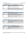
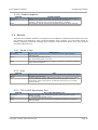
2.1.8. Pass Gateway Exceptions
Identifier
Description
Values
Pass Gateway exceptions
Defines are the Gateway exception replies from slave side passed to
master.
Enabled – Gateway exception replies are passed to Master
Notes
Disabled – Gateway exception replies are filtered away
This functionality is useful for debugging.
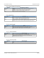
2.1.9. Serial Port
Identifier
Description
Values
Notes
Serial Port
Defines the serial port that Gateway uses for Modbus serial communication
Port 1 – Serial port 1 (RS-232 console/application port)
Port 2 – Serial port 2 (RS-232/422/485 application port)
If single serial port or RS-422/485 is required use Port 2. If Port 1 is used the
console switch of Arctic must be on Application position. DIP-switches below
the DB-9 serial connector specify the RS-232/422/485 settings of Port 2.
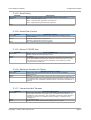
2.1.10. Serial Speed
Identifier
Description
Values
Notes
Speed
Defines the serial port speed for Modbus communication
300, 1200, 2400, 4800, 9600, 19200, 38400, 57600, 115200 bps
Check the speeds supported by connected Modbus equipment. If special
serial port speed is required please contact Viola Systems.
2.1.11. Serial Data Bits
Identifier
Description
Values
Notes
Serial Data bits
Defines the number of data bits used on Modbus serial communications
5, 6, 7, 8, Auto (8 for Modbus RTU, 7 for Modbus ASCII)
Check the data bits supported by connected Modbus equipment. Generally
Modbus RTU communication uses 8 data bits and Modbus ASCII
communication uses 7 data bits.
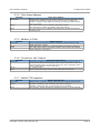
2.1.12. Serial Stop Bits
Identifier
Description
Values
Notes
Serial Stop bits
Defines the number of stop bits used on Modbus serial communications
1,2
Copyright © 2004, Viola Systems Ltd.
Page 8