1
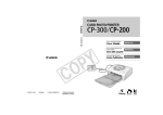
Stellaris® Brushed DC Motor Control Reference Design Kit U S E R ’S M A N U A L RDK-BDC-00 Co pyrigh t © 200 8 Lumin ary Micro, In c. Legal Disclaimers and Trademark Information INFORMATION IN THIS DOCUMENT IS PROVIDED IN CONNECTION WITH LUMINARY MICRO PRODUCTS. NO LICENSE, EXPRESS OR IMPLIED, BY ESTOPPEL OR OTHERWISE, TO ANY INTELLECTUAL PROPERTY RIGHTS IS GRANTED BY THIS DOCUMENT. EXCEPT AS PROVIDED IN LUMINARY MICRO’S TERMS AND CONDITIONS OF SALE FOR SUCH PRODUCTS, LUMINARY MICRO ASSUMES NO LIABILITY WHATSOEVER, AND LUMINARY MICRO DISCLAIMS ANY EXPRESS OR IMPLIED WARRANTY, RELATING TO SALE AND/OR USE OF LUMINARY MICRO’S PRODUCTS INCLUDING LIABILITY OR WARRANTIES RELATING TO FITNESS FOR A PARTICULAR PURPOSE, MERCHANTABILITY, OR INFRINGEMENT OF ANY PATENT, COPYRIGHT OR OTHER INTELLECTUAL PROPERTY RIGHT. LUMINARY MICRO’S PRODUCTS ARE NOT INTENDED FOR USE IN MEDICAL, LIFE SAVING, OR LIFE-SUSTAINING APPLICATIONS. Luminary Micro may make changes to specifications and product descriptions at any time, without notice. Contact your local Luminary Micro sales office or your distributor to obtain the latest specifications before placing your product order. Designers must not rely on the absence or characteristics of any features or instructions marked “reserved” or “undefined.” Luminary Micro reserves these for future definition and shall have no responsibility whatsoever for conflicts or incompatibilities arising from future changes to them. Copyright © 2008 Luminary Micro, Inc. All rights reserved. Stellaris, Luminary Micro, and the Luminary Micro logo are registered trademarks of Luminary Micro, Inc. or its subsidiaries in the United States and other countries. ARM and Thumb are registered trademarks, and Cortex is a trademark of ARM Limited. Other names and brands may be claimed as the property of others. Luminary Micro, Inc. 108 Wild Basin, Suite 350 Austin, TX 78746 Main: +1-512-279-8800 Fax: +1-512-279-8879 http://www.luminarymicro.com 2 November 1, 2008 Stellaris® Brushed DC Motor Control User’s Manual Table of Contents Chapter 1: Stellaris® Brushed DC Motor Control Reference Design Kit (RDK) Overview ........................ 3 Feature Summary ............................................................................................................................................... 4 Specification Overview ....................................................................................................................................... 4 Chapter 2: Using the Reference Design Kit ................................................................................................... 7 Reference Design Kit Contents .......................................................................................................................... 7 Important Information.......................................................................................................................................... 8 Developing with the RDK.................................................................................................................................... 8 Power Supply Selection ...................................................................................................................................... 8 Motor Selection ................................................................................................................................................... 9 Operating Modes ................................................................................................................................................ 9 Servo-Style PWM Input .................................................................................................................................... 10 Calibrating the PWM Input ............................................................................................................................ 10 Calibration Procedure ................................................................................................................................... 10 Electrical Interface ........................................................................................................................................ 10 CAN Communication ........................................................................................................................................ 11 Default Parameters ........................................................................................................................................... 12 Wiring................................................................................................................................................................ 12 Mechanical Drawing ......................................................................................................................................... 15 Status LED........................................................................................................................................................ 15 Jumper Settings................................................................................................................................................ 16 Fault Detection.................................................................................................................................................. 16 Fault Conditions ............................................................................................................................................ 16 Loss of CAN or Servo-style Speed Link........................................................................................................ 17 Chapter 3: BDC Can Console ........................................................................................................................ 19 Overview........................................................................................................................................................... 19 Using the Console ............................................................................................................................................ 20 Cables........................................................................................................................................................... 20 Set Up ........................................................................................................................................................... 20 Operation ...................................................................................................................................................... 21 Device List .................................................................................................................................................... 21 Firmware Update .......................................................................................................................................... 22 Help............................................................................................................................................................... 22 About............................................................................................................................................................. 22 Chapter 4: Firmware Updates and Debugging............................................................................................. 23 General Information .......................................................................................................................................... 23 Firmware Update Using CAN ........................................................................................................................... 23 How to Load Firmware from a PC to the BDC CAN Console ....................................................................... 23 Firmware Update Using BDC CAN Console................................................................................................. 25 Firmware JTAG/SWD ....................................................................................................................................... 26 Chapter 5: Hardware Description .................................................................................................................. 29 Hardware Description ....................................................................................................................................... 29 System Description ........................................................................................................................................... 29 Key Hardware Components.............................................................................................................................. 29 11/1/08 1 Schematic Description ...................................................................................................................................... 30 Microcontroller, CAN, and I/O Interfaces (Page 1) ....................................................................................... 30 Output Stage and Power Supplies (Page 2) ................................................................................................. 31 Chapter 6: Troubleshooting........................................................................................................................... 33 Appendix A: Schematics................................................................................................................................ 35 Appendix B: Board Drawing .......................................................................................................................... 39 Appendix C: Bill of Materials (BOM) ............................................................................................................. 41 Appendix D: Contact Information ................................................................................................................. 45 2 11/1/08 Stellaris® Brushed DC Motor Control User’s Manual List of Figures Figure 1-1. Figure 1-2. Figure 2-1. Figure 2-2. Figure 2-3. Figure 2-4. Figure 2-5. Figure 3-1. Figure 4-1. Figure 4-2. Figure 4-3. Figure 4-4. Figure 4-5. Figure 5-1. Figure 5-2. Figure 5-3. Figure B-1. 11/1/08 Brushed DC Motor Control Module ................................................................................................. 3 MDL-BDC Module Key Features (top view) .................................................................................... 5 MDL-BDC's Servo PWM Input Stage ............................................................................................ 11 Basic wiring with a Servo-style speed command for open-loop motor control .............................. 13 Wiring diagram showing CAN-based control for closed-loop motor control .................................. 14 MDL-BDC Mechanical Drawing..................................................................................................... 15 MDL-BDC Default Jumper Settings............................................................................................... 16 BDC CAN Console ........................................................................................................................ 19 Diagram showing the two-step firmware update process.............................................................. 23 Luminary Micro Flash Programmer Configuration......................................................................... 24 Transfer in Progress...................................................................................................................... 25 Locating the JTAG/SWD Connector.............................................................................................. 26 Firmware debugging using JTAG/SWD ........................................................................................ 27 MDL-BDC Circuit Board ................................................................................................................ 29 MDL-BDC JTAG/SWD Connector................................................................................................. 30 Network Connector Pin Assignments............................................................................................ 31 Component Placement Plot........................................................................................................... 39 1 2 11/1/08 Stellaris® Brushed DC Motor Control User’s Manual List of Tables Table 2-1. Table 2-2. Table 2-3. Table 2-4. Table 2-5. Table 3-1. Table 6-1. Table C-1. 11/1/08 Mabuchi RS-555PH-3255 Motor Specifications .............................................................................. 9 Control Method Comparison ........................................................................................................... 9 Recommended Values for External Resistor ................................................................................ 11 MDL-BDC Factory Default Configuration ...................................................................................... 12 Normal Operating Conditions ........................................................................................................ 15 RDK-BDC Available Cables ......................................................................................................... 20 Common Problems........................................................................................................................ 33 RDK-BDC Bill of Materials............................................................................................................. 41 1 2 11/1/08 C H A P T E R 1 Stellaris® Brushed DC Motor Control Reference Design Kit (RDK) Overview The RDK-BDC is a Luminary Micro reference design for the MDL-BDC, a Controller Area Network (CAN) based DC motor control. The MDL-BDC motor control module provides variable speed control for 12 V brushed DC motors at up to 40 A continuous current. Features include high-performance CAN networking as well as a rich set of control options and sensor interfaces, including analog and quadrature encoder interfaces. High-frequency PWM enables the DC motor to run smoothly and quietly over a wide speed range. MDL-BDC uses highly optimized software and a powerful 32-bit Stellaris LM3S2616 microcontroller to implement open-loop speed control as well as closed-loop control of speed, position, or motor current. The Reference Design Kit (RDK-BDC) contains an MDL-BDC motor control module as well as additional hardware and software for evaluating CAN communication. After evaluating the RDK-BDC, users may choose to either customize parts of the hardware and software design or use the MDL-BDC without modification. See the MDL-BDC board data sheet (available for download from www.luminarymicro.com) for complete technical specifications. Figure 1-1. November 1, 2008 Brushed DC Motor Control Module 3 Reference Design Kit (RDK) Overview Feature Summary The MDL-BDC control board provides the following features: Controls brushed 12 V DC motors up to 40 A continuous Controller Area Network (CAN) interface at 1 Mbit/s Industry standard servo (pulse-width modulation (PWM)) speed input interface Limit switch, encoder, and analog inputs Fully enclosed module includes fan cooling Flexible configuration options Easy to customize—full source code and design files available Factory source code compiles to less than 16 KB Specification Overview Key specifications of the MDL-BDC include: Quiet control of brushed DC motors – 15 kHz PWM frequency Two options for Speed control – Industry standard R-C servo type (PWM) interface – Controller Area Network (CAN) interface CAN communication – Multicast shared serial bus for connecting systems in electromagnetically noisy environments – 1 Mbits/s bit rate – CAN protocol version 2.0 A/B – Full configurability of module options – Real-time monitoring of current, voltage, speed, and other parameters Status LED indicates Run, Direction, and Fault conditions Motor brake/coast selector Limit switch inputs for forward and reverse directions Quadrature encoder input – Index input – 5 V supply output to encoder Analog input – Accepts 10kΩ potentiometer or 0-3 V input Screw terminals for all power wiring Headers (0.1 inch pitch) for all control signals For detailed specifications including electrical parameters, see the MDL-BDC data sheet. 4 November 1, 2008 Stellaris® Brushed DC Motor Control User’s Manual Figure 1-2. MDL-BDC Module Key Features (top view) Internal cooling fan Power terminals Mounting holes Motor terminals User switch Status LED CAN interface Ventilation slots CAN interface Servo-type speed control input Coast/Brake select Limit switch inputs Quadrature encoder input(QEI) Wire retention hooks November 1, 2008 Analog potentiometer input 5 Reference Design Kit (RDK) Overview 6 November 1, 2008 C H A P T E R 2 Using the Reference Design Kit This chapter provides information about the RDK-BDC kit contents and on using the RDK. Reference Design Kit Contents The RDK-BDC contains everything needed to evaluate 12 V brushed DC motor control. The RDK-BDC includes: MDL-BDC motor control module – Suitable for motors up to 12 V 40 A – Uses a Stellaris LM3S2616 microcontroller Mabuchi RS-555PH-5255 Brushed DC Motor – 5000 RPM, 12 V, 3 A Universal input wall power supply – 12 V 1.25 A – Plug adaptors for US, UK, EU, and AUST. BDC CAN console – Convenient tool for controlling key MDL-BDC functions – Integrated graphics display and navigation switches – Firmware update feature – Based on EK-LM3S2965 Evaluation Kit CAN cable – Connects the console to the MDL-BDC CAN terminator – Plug-in 120-Ω terminator USB cable – Provides power and communication to the BDC CAN console Adapter cable for ARM JTAG/SWD fine-pitch header – Luminary Part ADA2 Ribbon cable for ARM JTAG/SWD – 20-position cable for using the BDC CAN console as a debug interface Reference design kit CD – Complete documentation, including Quickstart and user’s guides – Luminary Micro Flash Programmer utility for firmware updates – Complete source code, schematics, and PCB Gerber files The source code can be modified and compiled using tools from Keil, IAR, CodeRed, CodeSourcery and GCC. November 1, 2008 7 Using the Reference Design Kit Important Information WARNING – In addition to safety risks, other factors that may damage the control hardware, the motor, and its load include improper configuration, wiring, or software. Minimize the risk of damage by following these guidelines. Always wear eye protection and use care when operating the motor. Read this guide before connecting motors other than the motor included in the RDK. DC motors may not be directly interchangeable and RDK parameter changes may be necessary before the new motor will operate correctly. Damage to the control board and motor can result from improper configuration, wiring, or software. Developing with the RDK The recommended steps for using the RDK are: Follow the Quickstart Guide included on the kit CD. The Quickstart guide will help you get the RS-555 motor up and running using the BDC CAN console in just minutes. It also contains important safety information that should be read before using the RDK. Use the BDC CAN console to evaluate and optimize target motor operation. Once the module is installed in the end application, use the BDC CAN console to configure and monitor motor operation. Using CAN, the console gives real-time access to a range of operating parameters. Customize and integrate the software and/or hardware to suit an end application. This user’s manual and the RDK-BDC Firmware Development Package User’s Guide are two important references for completing hardware and software modifications. New software can be programmed in the MDL-BDC using either the console (over CAN), or using a JTAG/SWD debug interface. The BDC console includes a JTAG/SWD debug interface feature. Power Supply Selection The MDL-BDC is designed primarily for use with 12 V sealed lead-acid batteries, although other power sources may be used as long as the voltage range is not exceeded. There are two important considerations when selecting a power supply. The first is finding a supply that can supply the starting current of the motor. Even unloaded motors may have a starting current that can momentarily exceed 60 A. Many switching power supplies will shut down very quickly when starting a brushed DC motor. The power supply does not need to maintain regulation during start, but it must ensure that the supply voltage remains above the under-voltage limit. The second consideration is how the power supply handles back-EMF and regeneration currents. During rapid deceleration of loads with high inertia, the motor acts as a generator. This current is rectified by the MDL-BDC back into the bus capacitor. As the capacitor charges, the voltage at the supply terminals may increase. It is important that the power supply can handle this momentary condition without entering a fault condition. The power supply must also present sufficiently low impedance so that the MDL-BDC’s voltage rating is not exceeded. A sealed lead acid battery easily meets these requirements. NOTE: The MDL-BDC does not have reverse polarity input protection. 8 November 1, 2008 Stellaris® Brushed DC Motor Control User’s Manual Motor Selection The MDL-BDC operates 12 V brushed DC motors. Typical motors include model BI802-001A from CIM and model RS-555PH-3255 from Mabuchi (see Table 2-1 for motor specifications). Some very small DC motors or motors in lightly loaded applications may have a limited useful speed range when controlled with PWM based voltage controls. The MDL-BDC can also drive resistive loads with some de-rating to allow for increased ripple current inside the module. See the MDL-BDC board data sheet for full specifications. Table 2-1. Mabuchi RS-555PH-3255 Motor Specifications Parameter Value Units Speed 3953 RPM Current 1.244 A Power 7.139 W Torque 17.25 mMm Speed 2325 RPM Current 3.627 A Power 14 W Torque 57.5 mMm No load speed 4650 RPM No load current 0.223 A At maximum efficiency At maximum power General characteristics Operating Modes The MDL-BDC can be controlled using either the servo-style PWM Input or the CAN interface. Table 2-1 compares the capabilities of each control method. Table 2-2. Control Method Comparison Control Method Servo-Style PWM input CAN Interface Speed Control Yes Yes Analog Position Control No Yes Encoder Position Control No Yes November 1, 2008 9 Using the Reference Design Kit Table 2-2. Control Method Comparison (Continued) Control Method Servo-Style PWM input CAN Interface Configurable Parameters No Yes Voltage, Current Measurement No Yes Limit Switches Yes Yes Coast/Brake Feature Yes Yes Firmware Update No Yes The MDL-BDC supports the simultaneous use of CAN for monitoring and the servo-style input for speed. Servo-Style PWM Input The MDL-BDC incorporates support for speed and direction control using the standard servo-style interface found on many radio-control receivers and robot controllers. See the MDL-BDC data sheet for specifications on the default timing of this signal. Calibrating the PWM Input To accommodate variation in the timing of the supplied signal, the MDL-BDC has a calibrate feature that sets new values for full-forward, full-reverse, and points in between. Calibration is typically only required in applications where the PWM source has uncertainties due to analog radio links or other variables. Direct digital sources are unlikely to require calibration. Calibration Procedure To calibrate the servo-style PWM input for a specific range: 1. Hold down the user switch for five seconds (see Figure 1-2 on page 5). 2. Set the controller to send a full-forward signal. 3. Set the controller to send a full-reverse signal. 4. Set the controller to send a neutral signal. 5. Release the user switch. The MDL-BDC samples these signals and centers the speed range and neutral position between these limits. If the MDL-BDC does not detect suitable servo signals during calibration, then the calibration fails. This condition is indicated by flashing the LED Red and Yellow. Electrical Interface The servo PWM input is electrically isolated from other circuits using an optocoupler. The MDL-BDC board data sheet contains electrical specifications, including common-mode voltage limits, for the input stage. 10 November 1, 2008 Stellaris® Brushed DC Motor Control User’s Manual Figure 2-1. MDL-BDC's Servo PWM Input Stage U3 J3 S + - 1 2 3 R5 150 FEMALE-1X3 PWM Speed Input 1 6 2 5 3 4 H11L1M The on-board resistor (R5) has been selected to allow a signal of only a few volts to drive the optocoupler. At 3.3 V or more it is advisable to add additional series resistance to limit the current into the LED. The PWM input stage is essentially a current-driven device, so the threshold for a logic high-level input is defined in milliamps. Some recommended values for an external resistor are listed in Table 2-3 Table 2-3. Recommended Values for External Resistor PWM Signal Level External Series Resistor Value 2.5 V 0 Ω (none) 3.0 V 0 Ω - 150 Ω 5.0 V 560 Ω 12 V 2.2 kΩ CAN Communication Controller Area Network (CAN) provides a powerful interface for controlling one or more MDL-BDC modules.The MDL-BDC has two RJ11/RJ14 sockets for daisy-chaining modules using standard cables. Each end of the CAN network should be terminated with a 120Ω resistor. The BDC CAN console has a built-in terminator. Each MDL-BDC module on the CAN bus is accessed using an assigned ID number. The ID defaults to 1, but can be changed by sending a CAN assign ID command to the bus. Pressing the USER switch on the MDL-BDC informs that particular module to accept the previously specified code. The CAN protocol used by the MDL-BDC includes the following capabilities: Firmware update over CAN Read supply voltage, motor voltage, temperature, and current Set motor voltage or target position Set control mode to speed or position Configure parameters Enable features such as closed-loop speed and position control. The CAN protocol provides a number of commands and divides them into groups based on the type of command. The commands are grouped according to broadcast messages, system level November 1, 2008 11 Using the Reference Design Kit commands, motor control commands, configuration commands, and motor control status information. The interface also provides a method to extend the network protocol to other devices by defining a CAN device encoding that takes into account device type and manufacturer. See the RDK-BDC Software User's Guide for complete details. The RDK-BDC includes a CAN board with an example application that demonstrates CAN control. Default Parameters The MDL-BDC parameters have the following default values. Parameters can be modified using CAN commands or by modifying the software source code. Parameters modified using CAN commands are volatile and must be reloaded if the power is cycled. Table 2-4 lists the factory default configuration of the MDL-BDC. Table 2-4. MDL-BDC Factory Default Configuration Parameter Default Value Accelerate rate Instantaneous change Deceleration rate Instantaneous change Motor control mode Open-loop speed control using voltage For additional information on parameters, see the RDK-BDC Firmware Development Package User’s Guide. Wiring The MDL-BDC is controlled using either a servo-type PWM source or CAN commands. Figure 2-2 on page 13 shows a typical simple wiring arrangement with power, motor, PWM control, and optional limit switch connections. Control wires should be looped through the wire retention hooks to prevent the connectors shaking loose during operation. 12 November 1, 2008 Stellaris® Brushed DC Motor Control User’s Manual Figure 2-2. Basic wiring with a Servo-style speed command for open-loop motor control Power In Motor Out (-) Supply (-) Motor (+) Supply (+) Motor (+) Digital Speed Signal (PWM) November 1, 2008 Normally -closed Normally -closed Forward Direction Limit Switch(es ) Reverse Direction Limit Switch(es) (-) 13 Using the Reference Design Kit Figure 2-3 shows an advanced wiring configuration using the CAN interface. Wiring for position sensing using both a position potentiometer and a quadrature encoder is detailed. Although two sensor types are shown, the MDL-BDC software supports control and monitoring of only one sensor at a time. Figure 2-3. Wiring diagram showing CAN-based control for closed-loop motor control Power In Motor Out (-) Supply / GND (-) Motor (+) Supply (+) Motor User switch sets CAN ID CAN cable to/from other devices CAN cable to/from other devices Normally-closed limit switches GND Reverse Limit H=Coast, L=Brake External coast/brake control (optional) GND GND +3V Reference 10kΩ Potentiometer position sensor (opt) 14 Forward Limit 0-3V signal GND GND Index signal B signal A signal +5V supply Encoder (opt) November 1, 2008 Stellaris® Brushed DC Motor Control User’s Manual Mechanical Drawing Figure 2-4 shows the MDL-BDC’s physical dimensions. The module has two 0.175" (4.5 mm) diameter mounting holes as indicated. Figure 2-4. MDL-BDC Mechanical Drawing Important: The MDL-BDC should be mounted so that the vents in the top and sides of the module are not restricted in any way. A clearance of ½ inch should be maintained around the module to aid cooling. Status LED Table 2-5 lists all LED status and fault codes. Fault information is prioritized, so only the highest priority fault will be indicated. Table 2-5. Normal Operating Conditions LED State Module Status Normal Operating Conditions Solid Yellow Neutral (speed set to 0) Fast Flashing Green Forward Fast Flashing Red Reverse November 1, 2008 15 Using the Reference Design Kit Table 2-5. Normal Operating Conditions (Continued) LED State Module Status Solid Green Full-speed forward Solid Red Full-speed reverse Fault Conditions Slow Flashing Yellow Loss of CAN or servo link Slow Flashing Red Fault Calibration or CAN Conditions Flashing Red and Green Calibration mode active Flashing Red and Yellow Calibration mode failure Flashing Green and Yellow Calibration mode success Slow Flashing Green CAN ID assignment mode Fast Flashing Yellow Current CAN ID (count flashes to determine ID) Flashing Yellow CAN ID invalid (that is, Set to 0) awaiting valid ID assignment Jumper Settings Figure 2-5 shows the factory default jumper settings. Figure 2-5. MDL-BDC Default Jumper Settings Coast / Brake (default = brake) Jumpers hold the limit switch inputs closed Fault Detection Software and hardware in the MDL-BDC continually monitors for various fault conditions. Fault Conditions A slow flashing Red LED indicates a fault condition. The MDL-BDC will detect and shutdown the motor if any of the following conditions are detected. 16 Power supply under-voltage Over temperature November 1, 2008 Stellaris® Brushed DC Motor Control User’s Manual Over current Limit switch activated in the current direction of motion The LED will indicate a fault state during the fault condition and for 3 seconds after the fault is cleared (except for the limit switch fault, which is cleared instantaneously). Loss of CAN or Servo-style Speed Link A slow flashing Yellow LED indicates that the MDL-BDC is not receiving a valid control signal. The control link error is cleared immediately when a CAN or PWM signal is restored. November 1, 2008 17 Using the Reference Design Kit 18 November 1, 2008 C H A P T E R 3 BDC Can Console The BDC CAN console, included in the RDK-BDC, provides a convenient way to evaluate some of the capabilities of the CAN interface. Overview The BDC CAN console is based on Luminary Micro's LM3S2965 Evaluation Board. The board ships with the console application ready to run. For more information on the capabilities of this board, see the LM3S2965 Evaluation Board User's Manual. Note that the LM3S2110 CAN Device board is not included in the Reference Design Kit. Figure 3-1. BDC CAN Console The application provides a simple user interface for the brushed DC motor controller board, running on the EK-LM3S2965 board and communicating over CAN. In addition to running the November 1, 2008 19 BDC Can Console motor, the motor status can be viewed, the CAN network enumerated, and the motor controller's firmware can be updated. Using the Console The CD included in the RDK-BDC contains a Quickstart guide that covers basic operation of the MDL-BDC and console. See this document for step-by-step instructions for connecting and using the RDK-BDC. Cables Table 3-1 shows several cables that are used in conjunction with the BDC CAN console and that are included in the RDK. Table 3-1. RDK-BDC Available Cables Cable Name Use CAN cable Connects the console to the MDL-BDC CAN terminator Plug-in 120 Ω terminator USB cable Provides power and communication to BDC CAN console ADA2 JTAG adapter Adapts 10-pin JTAG/SWD header to 20-pina JTAG ribbon cable 20-position cable for using the BDC console as a debug interfacea a. These cables are only required for software debugging. When controlling more than one MDL-BDC, modular cables (6P-4C or 6P-6C) should be used to link the modules. Suitable cables include the Digikey H2642R-07-ND cable. Set Up Power for the console comes from a USB cable. The CAN cable, also included in the RDK, has a RJ-11 6P-4C connector at one end and a 10-pin socket at the other end. Connect cables as follows: 1. Connect the CAN cable between the console CAN connector (P1) and either NET connector on the MDL-BDC. 2. Use RJ11/RJ14 modular cables to daisy-chain CAN communications to any other MDL-BDC devices. The cables should be 6-position with either 4 or 6 contacts installed. Suitable cables have plugs crimped on opposite sides of the cable and are referred to as reverse or straight cables, because pin 1 connects to pin 1. 3. The last MDL-BDC in the chain should have a CAN terminator inserted in its NET connector. The BDC CAN console has an integrated termination resistor, so it must be used as an endpoint. 4. Connect the USB cable between the BDC CAN console and the USB port of a PC. The console application software will then start (see Figure 3-1 on page 19). 5. If USB drivers were not previously installed, then follow the procedure in the Quickstart guide before proceeding. USB drivers are necessary for using the console board as a firmware update and/or debugging tool. 20 November 1, 2008 Stellaris® Brushed DC Motor Control User’s Manual Operation The direction buttons (left, right, up, and down) on the left side of the BDC CAN console are used to navigate through the user interface. The select button on the right side of the console is used to select items. The user interface is divided into several panels; the top line of the display always contains the name of the current panel. By moving the cursor to the top line and pressing select, a menu appears which allows a different panel to be displayed by pressing select again. The panels in the user interface will be individually discussed below. At startup, the Voltage Control Mode panel is displayed first. Voltage Control Mode The Voltage Control mode panel allows the motor to be controlled by directly selecting the output voltage. The speed of the motor is directly proportional to the voltage applied, and applying a “negative” voltage (in other words, electronically reversing the power and ground connections) will result in the motor spinning in the opposite direction. There are three parameters that can be adjusted on this panel; the ID, voltage, and ramp rate. The up and down buttons are used to select the parameter to be modified, and the left and right buttons are used to adjust the parameter's value. The following parameters can be adjusted: ID, which selects the motor controller to which commands are sent. If the ID is changed while the motor is running, the motor will be stopped. Voltage, which specifies the output voltage sent from the motor controller to the motor. A positive voltage will result in voltage being applied to the white output terminal and ground being applied to the green output terminal, while a negative voltage will apply voltage to the green output terminal and ground to the white output terminal. If the select button is pressed, changes to the output voltage will not be sent to the motor controller immediately (allowing the ramp to be used). The text color of the voltage changes from white to black to indicate that a deferred update is active. Pressing select again will send the final output voltage to the motor controller, creating a step function. Ramp, which specifies the rate of change of the output voltage. When set to “none”, the output voltage will change immediately. When set to a value, the output voltage is slowly changed from the current to the target value at the specified rate. This can be used to avoid browning out the power supply or to avoid over-torquing the motor on startup (for example preventing a loss of traction when a wheel is being driven). The bottom portion of the panel provides the current motor controller status. Three fault conditions are indicated: Over-Current fault (C) Over-Temperature fault (T) Under-Voltage fault (V) Device List This panel lists the motor controllers that reside on the CAN network. All 63 possible device IDs are listed, with those that are not present shown in dark gray and those that are present in bright white. By moving the cursor to a particular ID and pressing the select button, a device ID assignment will be performed. The motor controller(s) will wait for five seconds after an assignment request for its button to be pressed, indicating that it should accept the device ID November 1, 2008 21 BDC Can Console assignment. So, for example, if there are three motor controllers on a network, the following sequence can be used to give them each unique IDs: 1. Move the cursor to number 1 and press select. The LED on all three motor controllers will blink green to indicate that assignment mode is active. 2. Press the button on one of the motor controllers. It will blink its LED yellow one time to indicate that its ID is one. 3. Move the cursor to number 2 and press select. 4. Press the button on the second motor controller. It will blink its LED yellow two times to indicate that its ID is two. 5. Move the cursor to number 3 and press select. 6. Press the button on the third motor controller. It will blink its LED yellow three times to indicate that its ID is three. Once complete, this panel will then show that there are devices at IDs 1, 2, and 3. Firmware Update This panel allows the firmware on the MDL-BDC to be updated over the CAN network. A firmware image for the motor controller is first stored in the flash of the console board and then used to update the motor controller. See the “Firmware Updates and Debugging” on page 23 of this document for full details on this process. Help This panel displays a condensed version of this application help text. Use the up and down buttons to scroll through the text. About This panel simply displays the startup splash screen. 22 November 1, 2008 C H A P T E R 4 Firmware Updates and Debugging The MDL-BDC supports two methods for updating the firmware resident in the LM3S2616 microcontroller. The primary method uses the CAN interface and a Flash-resident boot loader for firmware transfer. During firmware development direct access and debug capability is preferable. The MDL-BDC included in the RDK has a JTAG/SWD connector installed for this purpose. General Information Firmware revisions released by Luminary Micro are referenced using four-digit numbers that increase with new releases, but are not necessarily contiguous (that is, numbers may be skipped). The flash memory region between 0x0000 and 0x07FF contains a CAN boot loader. The main firmware image should be loaded at 0x0800. Firmware Update Using CAN The MDL-BDC firmware can be updated over CAN using the BDC CAN console board included in the reference design kit. The capability to update the MDL-BDC firmware may also be added to any CAN Host controllers by implementing the necessary CAN protocol. The BDC CAN console comes with a firmware image already loaded and ready for transfer to the MDL-BDC. Of course updating the firmware is a redundant process unless the firmware in the console is newer than the firmware in the module. How to Load Firmware from a PC to the BDC CAN Console The MDL-BDC firmware is stored in the top of flash memory in the CAN console. This image can be replaced with new software using the resident serial flash loader and the LM Flash software from Luminary Micro. Figure 4-1. Diagram showing the two-step firmware update process PC running LM Flash Utility MDL-BDC Firmware Image 1 November 1, 2008 Transfer over USB (Virtual COM Port) MDL-BDC Firmware Image 2 Transfer over CAN 23 Firmware Updates and Debugging The console stores the MDL-BDC firmware image length at 0x20000 and the actual image starting at 0x20004. Step One: Install USB Drivers for the Console The USB driver installation is covered in the RDK-BDC Quickstart Guide. See that document for full details. Once the USB drivers are installed, the console appears as a Virtual Com port on your PC. Step Two: Install LM Flash Programmer Luminary Micro Flash Programmer is a Windows GUI (or command line) application for programming Stellaris microcontrollers using a variety of interfaces. Install and run the Luminary Micro Flash Programmer on a Windows PC. Step Three: Configure LM Flash Programmer for Serial Transfer Select the Configuration tab and from the Quick Set drop-down, select “Manual Configuration” (see Figure 4-2). Then select “Serial (UART) Interface” in the Interface drop-down menu. Next, select the COM Port assigned by Windows to the console board. This can be identified using the Windows Device Manager. Finally, verify that the baud rate is 115200 and then click the checkbox to Disable Auto Baud Support. Figure 4-2. Luminary Micro Flash Programmer Configuration Step Four: Program the Console with the MDL-BDC firmware Select the Program tab (see Figure 4-3). Then Browse to select the new binary file to download. The Program Address Offset is ignored by the console. Click on the Program button to start the transfer. 24 November 1, 2008 Stellaris® Brushed DC Motor Control User’s Manual The BDC CAN console automatically jumps to the Firmware Update panel when the transfer is initiated. Progress bars appear on the console display and the LM Flash Programmer window. Figure 4-3. Transfer in Progress When programming completes, the MDL-BDC firmware is resident in the console’s Flash memory. If an MDL-BDC with the currently selected CAN ID is connected, the console immediately starts a firmware update over CAN. The update over CAN may also be initiated manually. This procedure is covered in more detail in the following section called, “Firmware Update Using BDC CAN Console.” Firmware Update Using BDC CAN Console The following steps show how to transfer the firmware image from the console into the MDL-BDC. During this operation, the USB cable is required only as a power source to the console. Step One: Establish CAN connection Connect the console to the MDL-BDC using the CAN cable. Follow the “Set Up” on page 20 for step-by-step instructions. Move to Step 2 once the console screen shows a valid CAN connection to the MDL-BDC. Step Two: Navigation to the Firmware Update Panel Press the Up navigation switch to highlight the panel Title bar. The default mode is Voltage Control Mode. Press the select switch to bring up the list of panels. Navigate to the Firmware Update title and press select again to move to that panel. This panel allows the firmware on the MDL-BDC to be updated over the CAN network. A firmware image for the motor controller is first stored in the flash of the console board and then used to update the motor controller. November 1, 2008 25 Firmware Updates and Debugging The ID of the motor controller to be updated can be selected on this panel. By using the console-resident firmware image, multiple motor controllers can be updated (one at a time) using this panel, without the need to download from a PC each time. When not updating, the firmware version of the currently selected motor controller is displayed. If there is no motor controller on the CAN network with the current ID, the firmware version displays as “-”. By pressing the “Select” button when the “Start” button is highlighted, the motor controller firmware update starts. When the firmware is being transferred (either from the PC using the UART or to the motor controller using the CAN network), the ID, firmware version, and “Start” buttons will all be grayed out. A progress bar will appear below those buttons to indicate what is happening and the how far it is through the process. The MDL-BDC automatically restarts when the firmware update is complete. Firmware JTAG/SWD The MDL-BDC included in the RDK-BDC has a 2x10 header installed for firmware programming and debugging using JTAG/SWD. JTAG is a four-wire interface. SWD is a high-performance two-wire interface with similar capabilities. Figure 4-4. Locating the JTAG/SWD Connector JTAG/SWD Connector Pin 1 is at this end When using the JTAG/SWD cable, pay special attention to the location of pin 1 on the connector. When inserted correctly, the cable will run back across the bottom of the case, covering the Luminary Micro logo. See the Chapter 5, “Hardware Description,” for additional information on the JTAG/SWD connector. The BDC CAN console board is based on the Luminary Micro EK-LM3S2965 Evaluation board. 26 November 1, 2008 Stellaris® Brushed DC Motor Control User’s Manual The console board can be used as a low cost In-circuit Debug Interface (ICDI) for both programming and debugging. The ICDI circuit is compatible with the Luminary Micro Flash Programmer as well as leading development tools for ARM Cortex-M3. Evaluation versions for several tools are available from www.luminarymicro.com. Figure 4-5. Firmware debugging using JTAG/SWD Ribbon cable 10-pin to 20-pin Adapter Cable PC running LM Flash Utility or third-party Development tools USB November 1, 2008 27 Firmware Updates and Debugging 28 November 1, 2008 C H A P T E R 5 Hardware Description Hardware Description The MDL-BDC motor control module uses a highly integrated Stellaris LM3S2616 microcontroller to handle PWM synthesis, analog sensing, and the CAN interface. Only a few additional ICs are necessary to complete the design. The entire circuit is built on a simple two-layer printed circuit board. All design files are provided on the RDK CD. System Description A unique aspect of the MDL-BDC design is the integrated CAN interface and low-cost, fan-cooled MOSFET array that handles high current in a small form-factor. The motor control consists of an H-bridge arrangement which is driven by fixed-frequency PWM signals. Key Hardware Components Figure 5-1 shows the MDL-BDC circuit board with the enclosure and cooling fan removed. Figure 5-1. MDL-BDC Circuit Board DC Bus capacitor MOSFETs Current sense circuit JTAG/SWD connector (other side) Voltage regulators LM3S2616 Microcontroller User switch PWM input optocoupler 16MHz crystal Gate driver CAN connector CAN transceiver November 1, 2008 Status LED 29 Hardware Description Schematic Description Microcontroller, CAN, and I/O Interfaces (Page 1) Page 1 of the schematics details the microcontroller, CAN interface, and sensor interfaces. Microcontroller At the core of the MDL-BDC is a Stellaris LM3S2616 microcontroller. The LM3S2616 contains a peripheral set that is optimized for networked control of motors, including 6 high-speed ADC channels, a motor control PWM block, a quadrature encoder input, as well as a CAN module. The microcontroller's PWM module can generate two complementary PWM signal pairs that are fed to the power stage. The LM3S2616 has an internal LDO voltage regulator that supplies 2.5 V power for internal use. This rail requires only three capacitors for decoupling and is not connected to any other circuits. Clocking for the LM3S2616 is facilitated by a 16 MHz crystal. Although the LM3S2616 can operate at up to 50 MHz, in order to minimize power consumption, the PLL is not enabled in this design. The 32-bit Cortex-M3 core has ample processing power to support all features including 1 Mbits/s CAN with a clock speed of 16 MHz. Debugging The microcontroller supports JTAG and SWD debugging as well as SWO trace capabilities. To minimize board area, the MDL-BDC uses a 0.050" pitch header footprint which matches ARM's fine-pitch definition (Figure 5-2). The connections are located on the bottom of the module, under the serial number label. The module included in the reference design kit has a header installed; however, the standard MDL-BDC (available as a separate item) does not have the header installed. Some in-circuit debuggers provide a matching connector. Other ARM debuggers can be used with the adapter board included in the RDK. Figure 5-2. MDL-BDC JTAG/SWD Connector 1 2 TMS/SWDIO TCK/SWCLK TDO TDI SRSTn +3.3V GND GND GND 9 10 Figure 5-2 shows the pin assignments for the JTAG/SWD connector as viewed from the bottom (connector) side of the circuit board. CAN Communication A key feature of the LM3S2616 microcontroller is its CAN module that enables highly reliable communications at up to 1 Mbits/s. The MDL-BDC control board adds a standard CAN transceiver (U2), additional ESD protection (D2), and connectors. The pin assignments for the RJ11/RJ14 30 November 1, 2008 Stellaris® Brushed DC Motor Control User’s Manual 6P-4C connectors are defined in CAN in Automation (CiA DS102). Figure 5-3 shows the network connector pin assignments. Figure 5-3. Network Connector Pin Assignments CANL CANH V+ GND 1 6 CAN Socket Viewed from Top (Tab down) The V+ signal (Pin 2) is not used in the MDL-BDC, however, it is passed through to support other devices that either provide or use power from this terminal. The typical application for V+ is in providing a small amount of power to optocouplers for isolating CAN signals. Other Interfaces Several other interfaces are provided on 0.1" pin headers. The connections to the microcontroller are ESD-protected and in most cases have 10 kΩ pull-up resistors. The analog input has a 0 to 3V span. In order to use a 10 kΩ potentiometer, a 1 kΩ “padding” resistor is provided on J4.1 to drop 300 mV from the 3.3 V rail when the potentiometer is connected. Output Stage and Power Supplies (Page 2) Page 2 of the schematics details the power supplies, gate drivers, output transistors, sensing, and fan control circuits. Motor Output Stage The motor output stage consists of an H-bridge with High-/Low-side gate drivers. Each leg of the H-bridge has three paralleled MOSFETs. The MOSFETs are connected in parallel to reduce Rds (on) to about 1.8 mΩ and to provide additional surface area for fan cooling. The fan blows directly on the TO-220 MOSFETs, which are arranged radially around the DC bus capacitor. A plastic ring encompasses the MOSFETs which provide mechanical support and ensures that the tabs do not touch. The gate drivers provide up to 2 Amps of peak current to rapidly switch the gates of the MOSFETs when directed by the microcontroller's PWM module. The gate drivers are designed for high-voltage operation, but work equally well in this 12 V application. In a variation from their typical use, the PWM signal is applied to the Enable (ODn) input to modulate either the high or low side MOSFETs. A general-purpose output signal from the microcontroller controls the gate driver's PWM input which selects whether it is the high- or low-side that is being controlled by the November 1, 2008 31 Hardware Description microcontroller's PWM signal. In this configuration, dead-time, the delay between switching states on one half of an H-bridge, is only an issue when changing from forward direction to reverse direction. Because the high-side MOSFETs are N-Channel types, a positive Vgs is required to switch them on. The gate drivers use a simple boot-strapping technique to ensure that the high-side Vgs remains above the Vgs (on) threshold. Whenever the low-side MOSFETs are on, the associated boot-strap capacitor (C24 or C23) charges to ~12 V through the resistor-diode network. Later, when the high-side MOSFETs turn on, the boot-strap capacitor maintains power to the high-side driver with respect to the Motor terminal. One issue with the boot-strap capacitor method is that the capacitor voltage will decay to an unacceptable level unless a low-side MOSFET is periodically switched on. This state only occurs when the motor is running full-forward or full-reverse. The MDL-BDC software intermittently switches to the low-side MOSFETs for a short duration to replenish the bootstrap capacitor. The short duration has no impact on motor speed. Power Supply Two cascaded voltage regulators create 5 V and 3.3 V power supply rails from the 12 V input. 5 V is used only for the CAN transceiver and quadrature encoder functions. The cascaded arrangement also provides a way to spread the thermal dissipation of the linear regulators, with the 5 V taking most of the burden. 3.3 V is used by the MCU and peripheral circuitry. Current Sensing The current sensing circuit consists of a low-side shunt resistor (R35) and a non-inverting voltage amplifier. Due to the high current in the bridge, the shunt resistor is just 500 µΩ. Op-amp U8 amplifies the signal across R35 by a factor of 40. Because the sense resistor is in the low-side of the H-bridge, the current through it is only positive when the low-side MOSFETs are on. The software takes this into consideration when sampling the current waveform. Resistor R43 biases the op-amp input by +10 mV to allow for negative input offset voltage. The software automatically zeroes out this small offset before the motor is started. R42 and C25 form a low-pass filter to isolate the op-amp's power supply from the other devices on the +3.3 V power supply rail. Voltage Sensing A simple divider resistor network (R20/21 and R23) scales the 12 V rail down to the range of the ADC (0-3 V). Two additional dividers allow the bootstrap supplies to be monitored in software. This is an optional feature. Fan Control The cooling fan is self-contained and uses a small brushless DC motor. The MDL-BDC supports On/Off software control of the fan using Q13. The fan operates when the motor is running or when the temperature exceeds a certain threshold. The LM3S2616 microcontroller has an internal temperature sensor. A simple software table correlates the microcontroller temperature to overall system temperature. 32 November 1, 2008 C H A P T E R 6 Troubleshooting Although the MDL-BDC is simple to use, simple errors in wiring, software ,or use can affect normal operation. This chapter provides guidance on resolving common problems. Table 6-1. Common Problems Symptom Diagnosis Resolution No LED activity (LED always off) Power source is out of specification. Use a volt meter to confirm that 12 V is present between the Red/Black terminals and the polarity is correct. Incorrect firmware (possibly containing bugs, or intended for another target). Load new firmware into the console and re-program the MDL-BDC. No firmware loaded. Only the boot loader is resident in memory. Load firmware into the console and re-program the MDL-BDC. LED indicates under-voltage fault when running The power supply is unable to maintain voltage under load. Recharge battery or change to a power supply with a higher ampere rating. The LED blinks erratically when motor is running The power supply is unable to maintain voltage under load and is dropping below 6V which is resetting the MDL-BDC electronics. Recharge battery or change to a power supply with a higher ampere rating. Motor fails to run Limit switches are open. Install jumper shunts to hold limit switch inputs closed. Motor operates in one direction only Limit switch is open. Check limit switch operation or insert the appropriate jumper shunt. It is possible in this case that the module can not be updated via the CAN interface and, therefore, must be updated using JTAG/SWD. November 1, 2008 33 Luminary Micro Confidential—For Use Under NDA Only Troubleshooting 34 November 1, 2008 Luminary Micro Confidential—For Use Under NDA Only A P P E N D I X A Schematics This sections contains the schematic diagrams for the Intelligent Display Module. RDK-BDC MCU, Network, and Interface on page 36 RDK-BDC Power Supplies and Input Stage on page 37 November 1, 2008 35 Schematic page 1 1 2 3 4 5 6 J1 Status LED LED_RED SWITCH A Green D1 R2 CANTX CANRX 2 8 3 Red 150 1 4 2 TXD RXD CANH CANL CANH/SCL CANL/SDA VCC VREF R3 10K 3 5 CANSENSE SN65HVD1050D PIN 6 PIN 5 PIN 4 PIN 3 PIN 2 PIN 1 CAN/I2C Port RJ11-6P-VERT J2 +5V RS GND 7 6 R4 10K C1 0.1UF 2 SW-B3S1000 1 1 SW1 LED_GRN R1 100 U2 D2 GSOT05C 3 Calibrate/ID 6 5 4 3 2 1 6 5 4 3 2 1 PIN 6 PIN 5 PIN 4 PIN 3 PIN 2 PIN 1 A CAN/I2C Port RJ11-6P-VERT U1 RXD/SPDIN TXD LED_GRN CANRX CANTX PWMA CTRLA TCK/SWCLK TMS/SWDIO TDI TDO QE_A B QE_B LED_RED 17 18 19 20 21 22 25 26 52 51 50 49 11 14 15 16 30 31 34 35 Y1 PA0/U0RX PA1/U0TX PA2/PWM4 PA3/PWM5 PA4/CAN0Rx PA5/CAN0Tx PA6/PWM0 PA7/PWM1 PB0/PWM2 PB1/PWM3 PB2/I2C0SCL PB3/I2C0SDA PB4/C0PB5/C1PB6/C0+ PB7/NMI PC0/TCK/SWCLK PC1/TMS/SWDIO PC2/TDI PC3/TDO/SWO PC4/PhA0 PC5/C0o PC6/PhB0 PC7/C1+/C1o OSC0 OSC1 PD0/IDX0 PD1 PD2/ADC5 PD3/ADC4 PWMB PWMB CTRLB CTRLB CANH/SCL CANL/SDA CANSENSE FAN_ON FAN_ON LIMIT2 LIMIT1 61 62 63 64 BRAKE_EN VBOOTB U3 +3.3V +5V 6 C2 0.1UF R6 1.0K RXD/SPDIN 5 2 4 3 J3 R5 1 1 2 3 150 S + - FEMALE-1X3 PWM Speed Input H11L1M QE_INDEX +3.3V JP1 1 2 3 BRAKE_EN VBOOTB Brake (default) PE0/ADC3 PE1/ADC2 PE2/ADC1 PE3/ADC0 PE4/FAULT0 XOSC0 XOSC1 NC NC NC WAKE HIB VDDA VDD33 VDD33 VDD33 VDD33 6 5 2 1 8 VBOOTA POT/ANA ISENSE VSENSE SWITCH HDR-1X3 Brake/Coast Jumper 2 VBOOTA ISENSE VSENSE 1 GSOT05C 45 46 48 +3.3V R7 1.0K J4 1 2 3 POT/ANA + S - +3.3V C3 C4 10PF 10PF 32 33 R8 10K RESETn C9 0.01UF C 40 10 13 24 29 36 39 44 53 60 4 RST GND GND GND GND GND GND GND GND GND GNDA VBAT LDO VDD25 VDD25 VDD25 VDD25 3 12 28 43 59 C5 C6 C7 0.01UF 0.01UF 0.1UF D A 1 July '08 First production design. B 1 Aug '08 Improve Isense circuit. Change AIN pin-out. B1 5 Sept '08 Change R42 to 150 ohms. B2 20 Oct '08 Add R43 to op-amp circuit. Debug +3.3V TP1 R13 10K J7 1 3 5 7 9 2 4 6 8 10 +5V J5 1 2 3 4 5 C12 1UF 2 C + A B I - HDR-1X5 Encoder 1 +3.3V Description 1 D5 C10 C11 0.01UF 0.1UF Factory Test Date R11 10K QE_A QE_B QE_INDEX LM3S2616 Revision R10 10K GSOT05C 7 9 23 38 54 2 R9 10K 37 HDR-1X3 10K Position Pot D4 +3.3V C8 0.1UF +3.3V History B Coast D3 +3.3V 16.00MHz 41 42 47 27 58 57 56 55 TMS/SWDIO TCK/SWCLK TDO TDI RESETn RXD/SPDIN TP3 TXD TP4 TMS/SWDIO TP5 TCK/SWCLK TP6 TDO TP7 TP8 CON-HDR-2X5-050 TP9 R12 10K +3.3V TP2 J6 LIMIT2 1 2 Jumper Installed (default) D6 1 HDR-1X2 Limit Switch #2 (Reverse) +3.3V 2 R14 10K LIMIT1 TDI FANN GSOT05C FANN J8 GSOT05C D 1 2 Jumper Installed (default) HDR-1X2 Limit Switch #1 (Forward) Drawing Title: Jaguar Brushed DC Motor Control Page Title: MCU, Network and Interface Size Date: 1 2 3 4 5 B Document Number: 10/20/2008 RDK-BDC Sheet 6 1 of 2 Rev B Schematic page 2 4 5 D7 +12V CD0805-S0180 Q1 FDP8874 1 C13 1UF A R16 100 Q2 FDP8874 1 R17 100 Q3 FDP8874 1 R18 100 2 4.7 A 3 R15 2 +12V 6 3 3 2 2 3 1 GATE_BH 3 C19 C17 1UF 0.01UF ON NR R22 10K 1 C20 0.01UF Motor + 4 1 C18 1UF T4 C14 BOOT 1 (White) 1UF 2 CTRLB PWM HDRV 8 Q4 FDP8874 1 (Blk) 3 ODn SW GND PWMB R27 10K Q6 FDP8874 1 7 R24 100 5 R25 100 R26 100 GATE_BL VLO B 6 B LDRV Q5 FDP8874 1 2 C21 0.01UF NR 3 C16 1UF VSENSE R23 1.0K ON U6 FAN5109 2 25V T2 3 +12V VBOOTB 3 C15 3300UF R21 10K VOUT 2 V- R20 10K VIN R19 390K +3.3V 5 3 + VOUT 4 2 (Red) VIN GND T1 5 VCC 4 U5 PQ1LA333MSPQ +5V GND U4 PQ1LA503MSPQ 2 +12V POWER IN V+ +12V J9 D8 +12V CD0805-S0180 Q7 FDP8874 1 2 C22 1UF R29 100 Q8 FDP8874 1 R30 100 Q9 FDP8874 1 R31 100 2 4.7 3 R28 2 +12V 3 3 Q13 FDV301N 1 FAN_ON Red Black AMP MTA 2P 12V Fan 2 1 2 3 +12V FANN GATE_AH Cooling Fan Control Motor - R32 390K +12V U7 FAN5109 R42 R35 0.0005 OHM 3 PWMA R39 10K R41 10K ODn SW Q12 FDP8874 1 7 R36 100 5 R37 100 R38 100 GATE_AL VLO 6 LDRV Q11 FDP8874 1 2 Q10 FDP8874 1 2 HDRV 2 PWM 3 0.01UF R40 390K 1 8 VLO 1.0K 150 C25 0.1UF BOOT 3 C24 4 C C23 3 R34 5 +3.3V 1 2 CTRLA 3 1 ISENSE T3 (Green) 1UF R43 470K GND 2 U8 FAN4174IP5X VCC R33 10K 4 VBOOTA C Current Sense Amplifier D D Drawing Title: Jaguar Brushed DC Motor Control Page Title: Power Supplies and Output Stage Size Date: 1 2 3 4 5 B Document Number: 10/20/2008 RDK-BDC Sheet 6 2 of 2 Rev B Schematic page 3 A P P E N D I X B Board Drawing This appendix contains details on component locations, including: Component placement plot for top (Figure B-1) Figure B-1. Component Placement Plot November 1, 2008 39 40 November 1, 2008 A P P E N D I X C Bill of Materials (BOM) Table C-1 provides the BOM for the RDK-BDC. Table C-1. RDK-BDC Bill of Materials Item Ref Qty Part Number Description Mfg Supplier Stock No 1 C1, C2, C7, C8, C11, C25 6 C0805C104M5RACTU Capacitor, 0.1uF 50V 20% 0805 X7R Kemet Mouser 80-C0805C104M5R 2 C12, C13, C14, C16, C17, C18, C22, C23 8 TMK212BJ105KG-T Capacitor 1.0uF 25V X5R 0805 Taiyo Yuden Digikey 587-1291-1-ND 3 C15 1 ESMG250ELL332MN2 0S Capacitor, 3300uF 25V Electro 20x20mm UCC Digikey 565-1066-ND 4 C3, C4 2 C0805C100J5GACTU Capacitor 10pF 50V 5% Ceramic NPO/ COG 0805 Kemet Mouser 80-C0805C100J5G 5 C5, C6, C9, C10, C19, C20, C21, C24 8 C0805C103J5RACTU Capacitor, 0.01uF 50V 5% 0805 X7R Kemet Mouser 80-C0805C103J5R 6 D1 1 WP59SRSGW/CC WP59EGW LED, Bi-Color Red/ Grn 5mm Com Cathode Kingbright Digikey Mouser 754-1235-ND 7 D2, D3, D4, D5, D6 5 GSOT05C / SM05T1GOS Diode, Dual ESD Protection Device SOT-23 Vishay Digikey 751-1415-2-ND 754-1232-ND 8 D7, D8 2 CD1005-S0180 Diode, 80V high speed 1005 size Bourns Mouser 652-CD1005-S0180 9 J1, J2 2 90512-003LF 04911 Connector, RJ11 Mod-Jack 6-4 Vert Flange Blk FCI 4ucon Digikey 4ucon 609-1064-ND 04911 10 J3 1 PPTC031LFBN-RC 00526 Connector, Female 1x3 socket 0.1" 8.5mm gold flash Sullins 4ucon Digikey 4ucon 11 J4, JP1 2 00798 Header 1x3 0.1" 6mm contact 3mm tail gold 4ucon 4ucon November 1, 2008 S7001-ND 00526 00798 41 Table C-1. RDK-BDC Bill of Materials (Continued) Item Ref Qty 12 J5 1 00806 13 J6/8 1 14 J7 15 42 Part Number Mfg Supplier Stock No Header 1x5 0.1" 6mm contact 3mm tail gold 4ucon 4ucon 00806 15948 Header 2x2 0.1" 6mm contact 3mm tail gold 4ucon 4ucon 988 0 M50-3500542 Connector, 2x5 Header 1.27mm pitch (OMIT) Harwin Mouser 855-M50-3500542 J9 1 35362-0210 Connector, 2 Pin Sherlock 2mm vert header Molex Arrow 35362-0250 16 JP1b, J6b, J8b 3 151-8000 Jumper Shunt 0.1"gold Kobiconn 4ucon Mouser 4ucon 17 Q1, Q2, Q3, Q4, Q5, Q6, Q7, Q8, Q9, Q10, Q11, Q12 12 FDP8874 Mosfet N-Channel V 30V 114A TO-220 Fairchild Arrow FDP8874 18 Q13 1 FDV301N Mosfet N Channel SOT-23 Fairchild Arrow FDV301NTR-ND 19 R1, R16, R17, R18, R24, R25, R26, R29, R30, R31, R36, R37, R38 13 Resistor, 100 ohms 5% 0805 Panasonic Digikey P100ATR-ND 20 R15, R28 2 Resistor, 4.7 Ohms 5% 0603 Panasonic Digikey P4.7ATR-ND 21 R2, R5, R42 3 Resistor, 150 ohms 5% 0805 Panasonic Digikey P150ATR-ND 22 R6, R7, R23, R34 4 Resistor 1.0K 1% 0805 Panasonic Digikey P1.00KCTR-ND 05734 Description 151-8000 05734 November 1, 2008 Stellaris® Brushed DC Motor Control User’s Manual Table C-1. RDK-BDC Bill of Materials (Continued) Item Ref Qty 23 R3, R4, R8, R9, R10, R11, R12, R13, R14, R20, R21, R22, R27, R33, R39, R41 16 24 R35 25 Mfg Supplier Stock No Resistor, 10.0K 1% 0805 Panasonic Digikey P10.0KCTR-ND 1 Resistor 0.0005 Ohms 2W 1% 2512 Stackpole Digikey CSNL20.00051%RT R-ND R19, R32, R40 3 Resistor 390K 1% 0805 Vishay Digikey 541-390KCRTR-ND 26 R43 1 Resistor 470K 1% 0805 Panasonic Digikey P470KCTR-ND 27 SW1 1 B3S-1000P Switch, Momentary Tact 160gmf 6mm Omron Arrow / Future SW415-ND 28 T1 1 7701-2 Terminal, Screw Vertical 15A Red Screw Keystone Bisco 7701-2 29 T2 1 7701-3 Terminal, Screw Vertical 15A Black Screw Keystone Bisco 7701-3 30 T4 1 7701-4 Terminal, Screw Vertical 15A White Screw Keystone Bisco 7701-4 31 T3 1 7701-6 Terminal, Screw Vertical 15A Green Screw Keystone Bisco 7701-6 32 U1 1 LM3S2616 IC, Microcontroller Stellaris Cortex-M3 64-TQFP Luminary Luminary LM3S2616 33 U2 1 SN65HVD1050D IC, CAN Transceiver SO-8 TI Arrow / Digikey 296-19416-5-ND 34 U3 1 H11L1SR2VM H11L1SR2M IC, Optocoupler Schmitt Trigger SMD-8 Fairchild Arrow H11L1SR2VM H11L1SR2M 35 U4 1 PQ1LA503MSPQ IC, Voltage regulator 5.0V 500mA SOT89-5 Sharp Mouser 852PQ1LA503MSPQ November 1, 2008 Part Number Description 43 Table C-1. RDK-BDC Bill of Materials (Continued) Item Ref Qty Part Number 36 U5 1 PQ1LA333MSPQ 37 U6, U7 2 38 U8 39 Description Mfg Supplier Stock No IC, Voltage regulator 3.3V 500mA SOT89-5 Sharp Mouser 852PQ1LA333MSPQ FAN5109BMX IC, Half-Bridge Gate Driver SO-8 Fairchild Arrow FAN5109BMX 1 FAN4174IS5X_NL IC, Op-amp Rail-toRail SOT-23 Fairchild Arrow FAN4174IS5X Y1 1 NX5032GA16.000000MHZ Crystal, 16.00MHz 5.0x3.2mm SMT NDK Digikey 644-1037-2-ND 40 Z 1 8902 LED standoff, plastic 0.16" for LED D1 Keystone Mouser 534-8902 41 Z 1 BD-BDC-B2 PCB, FR-406 2-layer 3.375"x3.500" 2-oz finished Advanced Advanced BD-BDC-B2 Part Number Description Mfg Supplier Stock No EBM / Sunon EBM Direct / Digikey 412-FH 259-1351-ND Cypress Cypress LM-0608-01 116 Final Assembly Item 44 Ref Qty F1 1 412-FH KDE1204PFV2.11.MS. A.GN Fan 12VDC 40x40x10mm 7CFM w/ 2" lead w/ Molex Sherlock connector F2 1 LM-0608-01 Enclosure, ABS plastic 3 pieces F3 4 90380A110 Screw, #4 x 0.500" plastite (for fan ) McMaster McMaster 90380A110 F4 4 90380A108 Screw, #4 x 0.375" plastite (for enclosure) McMaster McMaster 90380A108 November 1, 2008 A P P E N D I X D Contact Information Company Information Luminary Micro, Inc. designs, markets, and sells ARM Cortex-M3-based microcontrollers (MCUs). Austin, Texas-based Luminary Micro is the lead partner for the Cortex-M3 processor, delivering the world's first silicon implementation of the Cortex-M3 processor. Luminary Micro's introduction of the Stellaris® family of products provides 32-bit performance for the same price as current 8- and 16-bit microcontroller designs. With entry-level pricing at $1.00 for an ARM technology-based MCU, Luminary Micro's Stellaris product line allows for standardization that eliminates future architectural upgrades or software tool changes. Luminary Micro, Inc. 108 Wild Basin, Suite 350 Austin, TX 78746 Main: +1-512-279-8800 Fax: +1-512-279-8879 http://www.luminarymicro.com Support Information For support on Luminary Micro products, contact: [email protected] +1-512-279-8800, ext. 3 November 1, 2008 45 46 November 1, 2008