1
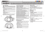
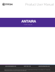
International Journal of Advanced Technology & Engineering Research (IJATER)
INTRODUCTION OF SVGA UNIT IN LEON3
PROCESSOR
Prachi Tyagi,
SVITS, INDORE,
[email protected]
Abstract
Gaisler Research develops and supports the LEON SPARC
V8 processor, a synthesizable processor core for embedded
applications. It is of interest to introduce a SVGA (Super
Video Graphics Array) in LEON3 to demonstrate the capabilities of the processor. The paper presents how SVGA is
introduced in the LEON3 processor with additional cores
from the GRLIB IP (Intellectual Property) library developed
by Gaisler Research. The complete work is realized as a
System on Chip (SOC) design. .LEON has been programmed entirely in VHDL (the main reason for the choice
of this language for the work) by Jiri Gaisler of the European
Space Agency.
I.
Introduction
The platform is based on the AMBA SoC bus protocol and
incorporates a novel interfacing scheme which utilizes the
bus hierarchy within AMBA in order to allow SVGA to be
integrated to the SoC platform utilizing the LEON Processor. The interface connects the IP cores directly to the AMBA bus hierarchy.
II.
LEON3 Processor-An Overview [1]
The LEON3 is a 32-bit processor based on the SPARC V8
architecture. Features of LEON3 are•SPARC V8 integer unit with 7-stage pipeline
• Hardware multiply, divide and MAC units
• Separate instruction and data caches
• Support for 2 - 32 register windows
• Radix-2 divider (non-restoring)
•Single-vector trapping for reduced code size
• Advanced debug support unit
• Optional IEEE-STD-754 compliant FPU
• 20 DMIPS at 25 MHz system clock
• Fault-tolerant version available
•Support for Fusion, IGLOO, ProASIC3E/L, RT ProASIC3,
Axcelerator and RTAX
Fig.1- Block diagram of LEON3 processor
III.
SVGA
An improved variation of the VGA (Video Graphics Array)
display standard, sometimes referred to as SVGA (Super
VGA), Ultra VGA is a standard for computer screen display
and resolution. IBM introduced the VGA standard in 1987 in
order to allow display of higher resolution images and a
greater number of colors (256 out of a possible 16 million
colors). VGA is an analog format that replaced the preceding
digital formats. Although replacing digital with analog
seems like it would not be considered progress, VGA actually increased the capacity to make signal variations and provided the ability to offer more color combinations than digital would allow at the time. The UVGA/SVGA standard,
although it supports up to 16 million colors, is limited in
specific machines and graphics cards by the amount of video
memory that is installed in the system. Although one system
might allow the whole palette of colors, another might allow
only 256.
Pixels on screen
To begin we need to understand how a SVGA monitor
works. The monitor screen for SVGA contains 800 columns
by 600 rows of picture elements called pixels (see fig.2). An
image is displayed on the screen by turning on and off individual pixels.
ISSN No: 2250-3536
Volume 2, Issue 4, July 2012
157
International Journal of Advanced Technology & Engineering Research (IJATER)
these three-color signals as digital signals, so we can just
turn each one on or off. As a result, the circuit is capable of
displaying only eight colors (23 = 8). [2]
800 pixels per row
Column 0
Column 799
Sync timings
Row 0
HSYNC
Horizontal Retrace Horizont
-al scan
Vertical Retrace
For section B of the horizontal synchronization signal, you
need 3.2 which are approximately 128 clock cycles
(3.2/.025). For section C in Figure 2.2 (a), you need 2.2 μs,
which is approximately 88 clock cycles, similarly we need
800 clock cycles (section D) for 800 columns of pixels and
40 clock cycles for section E. The total no. of clock cycles
needed for each row scan is 1056 cycles (128+88+800+40)
.With 40 MHz clock section D requires exactly 800 cycles,
generating 800 columns per row.
( 600 pixels per column)
Row
599
Figure 2. The SVGA monitor has 800 columns and 600 rows.
Scanning starts from row 0, column 0 and moves to the right
and down until reaching row 599 column 799.
The monitor continuously scans through the screen, rapidly
turning individual pixels on and off. Figure 2 shows scanning starts from row 0, column 0 in the top left corner of the
screen and moves to the right until it reaches to the last column. When the scan reaches the end of row, it retraces to the
beginning of next row. When it reaches the last pixel in the
bottom right corner of the screen, it retraces back to the top
left corner and repeats the scanning process. In order to reduce flicker on screen, the entire screen must be scanned 60
times per sec. during the horizontal and vertical traces all the
pixels are turned off.
Five control signals
The SVGA monitor is controlled by five signals: red, green,
blue, horizontal synchronization and vertical synchronization. The three color signals, collectively referred to as the
RGB signal, control the color of a pixel at a give location
on the screen. They are analog signals with voltages ranging
from 0.7 to 1 V. Different color intensities are obtained by
varying the voltage. For simplicity, our circuit will treat
ISSN No: 2250-3536
A row scan begins with the horizontal sync signal going low
for 3.2 µs (see section B in fig.2.2 (a)).A 2.2 µs high on the
signal follows this (see section C in fig.2.2 (a)).Next, the
data for three color signals is sent, one pixel at a time for the
800 columns for 20 μs. Finally, after the last column pixel,
there is another 1 μs of inactivity on the RGB signal lines for
the horizontal retrace before the horizontal sync signal goes
low again for the next row scan. The total time to complete
one row scan is 26.4 μs.
VSYNC
The timing for the vertical sync signal is analogous to the
horizontal one. The 105.6-μs active low vertical sync signal
resets the scan to the top- left corner of the screen (see section P in Figure 2.2 (b)). A 607.2-μs high follows this on the
signal. Next, there are the 800, 26.4-μs row scans, giving a
total of 15840 μs (800x26.4), as shown in section R. Finally,
after the last row scan, there are another 26.4 μs before the
vertical sync signal goes low again to start another complete
screen scan in the top left corner. It takes a total of 16,579.2
μs to complete one full screen scan.
Because the vertical sync signal is analogous to the horizontal sync signal, we can perform the same calculations as with
the horizontal sync regions to obtain the number of cycles
needed for each vertical region. However, instead of using
the number of periods of a 40-MHz clock, the times for each
vertical region are multiples of the horizontal cycle. For example, the time for a horizontal cycle is 26.4 μs, and section
P requires 105.6 us which is approximately two horizontal
cycles (4× 26.4). Section Q requires 607.2 µs, which equals
23 horizontal cycles (607.2/40). The calculation for section
R is 600 horizontal cycles (15840 μs/40 μs). Of course, it has
Volume 2, Issue 4, July 2012
158
International Journal of Advanced Technology & Engineering Research (IJATER)
to be exactly 600 times, because we need to have 600 rows
per screen. The number of horizontal cycles required by
the four regions in the vertical sync signal is also summarized in Table 1.Similarly we can use another counter for the
vertical sync signal. The clock for this counter is derived
from the horizontal counter so that the vertical counter
counts once for each horizontal cycle.
SVGA has been coded using VHDL language. Signals used
as input and output can be viewed in the following RTL
diagram.
clk
r
reset
g
b
SVGA
hsync
vsync
Fig 4. RTL view of SVGA
V. Interfacing with LEON3 processor
GRLIB
Fig. 3 (a) Horizontal Sync Timings (b) Vertical Sync Timings
TABLE 1. SVGA Timings
HORIZONTAL
TIMING
VISIBLE AREA
FRONT PORCH(FP)
SYNC PULSE
BACK PORCH (BP)
WHOLE LINE
VERTICAL TIMING
VISIBLE AREA
FRONT
PORCH(FP)
SYNC PULSE
BACK PORCH (BP)
WHOLE LINE
PIXEL
TIME (µs)
800
40
128
88
1056
20
1
3.2
2.2
26.4
LINE
TIME (ms)
600
1
15.84
0.0264
4
23
628
0.1056
0.6072
16.5792
IV. Implementation of SVGA
ISSN No: 2250-3536
The GRLIB IP-library is developed for SOC designs and is a
set of reusable IP-cores. The IP cores are bus-centric around
the AMBA AHB bus and use a coherent method for simulation and synthesis. The library is vendor independent and
expandable with support for different CAD-tools and target
technologies. Using GRLIB gives the developer great possibilities to design our own SOC design.
GRLIB is organized as a collection of VHDL libraries where
each IP-vendor has its own library name. A library usually
consists of a number of packages declaring the IP-cores as
components and registers used by the core. A unique plug &
play method gives the opportunity to configure and connect
IP-cores to fit the designers demands. This without the need
to change any global resources, ensuring that changes in one
vendor’s library don’t affect other vendor’s libraries. Simulation and synthesis scripts are automatically generated by a
global make file and have compatibilities to the following
simulation tools: Modelsim, NcSIM and GHDL. Synthesis
tools from Synopsis, Synplify, Cadence, Altera and Xilinx
are also supported. But here we are using Altera tool. [4]
At the heart of the system is a LEON SPARC microprocessor. This microprocessor is able to access SVGA via a special bus for embedded applications, called AMBA (Advanced Microprocessor Bus Architecture). To access memory, LEON must use a special memory controller hence
SDRAM controller is also designed and interfaced with
AMBA bus. Hence by externally interfacing SVGA we can
easily display anything.
Volume 2, Issue 4, July 2012
159
International Journal of Advanced Technology & Engineering Research (IJATER)
SVGA
AMBA BUS
MEMORY
CONTROLLER
LEON3
PROCESSOR
MEMORY
BUS
SDRAM
Fig. 5 Block diagram depicting the interfacing
VI. Conclusion and future work
This paper mainly describes the design and simulation of
SVGA which is based on FPGA and ALTERA (Quartus
tool) tools. By using these tools time required to get desired
results has become less. VHDL has been used to enter hardware description. VHDL codes have been written, synthesized, and mapped successfully. SVGA designed and interfaced with LEON3, fully complies with design requirements.
While most of the set objectives have been achieved, there is
still room for further improvement and experimentation. If
more time was given to work on this project, a number of
different goals could be considered .In this project, SVGA,
which is only 800x600 display resolutions, is taken. We can
further change the resolution like 1024x768, 1024x600, and
1360x768.Additional features like gaming can be done on
SVGA. Though the code is functional, rewriting it could still
be beneficial in respect to eliminating the residual timing
errors.
References
[1].
Aeroflex Gaisler, SPARC V8 32 bit Processor
LEON3/LEON3-FT Companion Core Datasheet,
Copyright © March 2010 Aeroflex Gaisler AB.
[2].
Build a VGA monitor controller, Enoch Hwang
[3].
Design Recipes for FPGAs, Dr Peter R. Wilson.,
ELSEVIER publications
[4].
GRLIB IP Core User’s Manual Version 1.1.0 B4113, January 2012
ISSN No: 2250-3536
Volume 2, Issue 4, July 2012
160