1
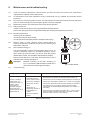
Medical–Biological
Research & Technologies
Inteliwasher
3D-IW8
Microplate washer
Operating Manual
Certificate
for version
V.2AW
Contents
1
Safety Precautions . . . . . . . . . . . . . . . . . . . . . . . . . . . . . . . . . . . . . . . . . . . . . . . . . . . . . . . . . . . . . . . . 3
2
General information . . . . . . . . . . . . . . . . . . . . . . . . . . . . . . . . . . . . . . . . . . . . . . . . . . . . . . . . . . . . . . . 5
3
Getting started . . . . . . . . . . . . . . . . . . . . . . . . . . . . . . . . . . . . . . . . . . . . . . . . . . . . . . . . . . . . . . . . . . . 6
4
Operation . . . . . . . . . . . . . . . . . . . . . . . . . . . . . . . . . . . . . . . . . . . . . . . . . . . . . . . . . . . . . . . . . . . . . 10
5
Operation closedown . . . . . . . . . . . . . . . . . . . . . . . . . . . . . . . . . . . . . . . . . . . . . . . . . . . . . . . . . . . . . 13
6
Program error messages . . . . . . . . . . . . . . . . . . . . . . . . . . . . . . . . . . . . . . . . . . . . . . . . . . . . . . . . . . 14
7
Specifications . . . . . . . . . . . . . . . . . . . . . . . . . . . . . . . . . . . . . . . . . . . . . . . . . . . . . . . . . . . . . . . . . . 15
8
Maintenance and troubleshooting . . . . . . . . . . . . . . . . . . . . . . . . . . . . . . . . . . . . . . . . . . . . . . . . . . . 16
9
Warranty, Reclamation Information . . . . . . . . . . . . . . . . . . . . . . . . . . . . . . . . . . . . . . . . . . . . . . . . . . 18
10
Glossary . . . . . . . . . . . . . . . . . . . . . . . . . . . . . . . . . . . . . . . . . . . . . . . . . . . . . . . . . . . . . . . . . . . . . . 19
11
Marking . . . . . . . . . . . . . . . . . . . . . . . . . . . . . . . . . . . . . . . . . . . . . . . . . . . . . . . . . . . . . . . . . . . . 20
Version 2.04 – March 2014
Page 2
Contents
Inteliwasher 3D-IW8
1.
Safety precautions
Attention!
Please make sure you have fully read and understood the Manual before using the
equipment and pay special attention to sections marked by this symbol.
Note:
Paragraphs marked with this symbol contain information about important functions and
use of the device.
GENERAL SAFETY PRECAUTIONS
·Use only as specified in the Operating Manual provided.
·Protect the unit from shocks and falling.
·After transportation or storage, keep the unit at room temperature for 2-3 hours before connecting to the
mains.
·Use only cleaning and decontamination methods recommended by the manufacturer.
·Do not make modifications to the design of the unit.
·Before diagnostics, study carefully the possibilities and operation procedures of the unit in order to obtain
reproducible and credible results. Check any unclear issues with the supplier.
·It is not recommended to leave the operating unit unattended for a long period.
·Change the bottles or connecting tubes only when the unit is switched off.
·In case of doubt about the quality and uniformity of the completed washing program, disregard the
results obtained and repeat the washing procedure.
·Accuracy of the obtained testing results depends on the quality of the microplate rinsing procedure. To
assure correctness of the rinsing procedure, regularly exercise visual control over reproducibility of liquid
volume dosing.
ELECTRICAL SAFETY
·Connect only to an external power supply unit with voltage corresponding to that on the serial number
label. Use only the external power supply unit provided with this product.
·Do not plug the power supply unit into an ungrounded power socket, and do not use an ungrounded
extension lead.
·Ensure that the switch and external power supply connector are easily accessible during use.
·Disconnect the unit from the mains before relocating it.
·If liquid penetrates into the unit, disconnect it from the mains and do not use it until it is checked by a
repair and maintenance technician.
·Do not operate the unit in premises where condensation can form. Operating conditions of the unit are
defined in the Specifications section.
1. Safety precautions
Inteliwasher 3D-IW8
Version 2.04 – March 2014
Page 3
DURING OPERATION
·Do not operate the unit in environments with aggressive or explosive chemical mixtures. Please contact
manufacturer for possible operation of the unit in specific atmospheres.
·Do not operate the unit if it is faulty.
·Always have the cover protecting against aerosol spread (hereinafter protective cover) installed during
operation.
·Do not operate the unit if any needle is clogged or malfunctions.
·Never touch the needles or place fingers or other parts under the needles during operation. Manifold
needles are sharp and can cause injury.
·Always switch off the unit before changing the manifold.
·Do not allow the waste bottle to overflow the maximum level during operation (there is a mark on the side
surface of the bottle). Take necessary precautions utilizing waste liquid in accordance with general
laboratory standards.
AFTER OPERATION
·Сarry out the cycle of system washing (on the unit front panel, use the button System rinsing) with
distilled water and do not dry. This will keep the system in permanent operation condition.
BIOLOGICAL SAFETY
·It is the user's responsibility to carry out appropriate decontamination if hazardous material is spilt on or
penetrates into the equipment.
·In diagnostic researches, potentially dangerous biological materials can be used. When working with
such materials, always use protective clothing and eye protection. Always have the protective cover
installed during operation.
Version 2.04 – March 2014
Page 4
1. Safety precautions
Inteliwasher 3D-IW8
2.
General information
Inteliwasher 3D-IW8 series microplate washer is designed for washing various types of standard
microtitre plates, microstrips and microarrays on FastFRAME (rectangular well shape). It is suitable for washing
wells with different bottom shapes: flat, U-shape and V-shape. The unit is fully programmable ensuring multi-step
solution ripening, aspiration (aspiration, combination of aspiration/liquid dispensing and soaking, as well as
soaking cycle during a particular period of time).
The unit has 50 programs divided into 5 following aspiration categories (see scheme1 below):
Type 1 (1.0 – 1.9) IPF96 U/V is intended for U-shape and V-shape immunoplates, 1 point aspiration.
Type 2 (2.0 – 2.9) IPF96 FLAT-2 is intended for flat-bottom shape immunoplates, 2 point aspiration.
Type 3 (3.0 – 3.9) IPF96 FLAT-C is intended for rectangular shape immunoplates, full-circle aspiration
direction.
Type 4 (4.0 – 4.9) FastFRAME-2 is intended for multi-slide* plate with rectangular wells.
Type 5 (5.0 – 5.9) FastFRAME-C is intended for multi-slide* plate with rectangular wells.
3
4
5
6
7
8
9
10
11
12
1
B
C
D
E
F
G
H
2
3
4
5
6
7
8
A
Fast ® FRAME
2
Fast frame
multi-slide plate
Immunoplate
1
A
B
C
D
E
F
G
H
Scheme 1
* – The FastFRAME (Schleicher&Shuell) multi-slide plate or analog plate of another manufacturer, that is
compatible with standard 1 x 3 inch (25 x 76 mm) glass slides.
NOTE:
Optional 4-channel washing solution weight logger, 4CHW Logger allows automatic
buffer bottles and waste bottle volume control.
The unit is supplied with 8-channel washing head for dispensing/aspiration, 3 bottles for washing and
rinsing solutions, a waste bottle and small bottle with hydrophobic filter that eliminates risk of contamination with
bacteria, viruses and infected particle from wasted liquid to an atmosphere. Hydrophobic filter bacterial
efficiencies is very high, up to 99.999% particles bigger than 0.027 micron (which is smaller than Hepatitis A, B
and C).
The unit provides:
·washing mode;
·rinsing mode;
·mixing mode;
·single point, two point, circular (circle or rectangular path);
·possibility of additional solution mixing during time gap between two work cycles;
·possibility to use microtest plates by different manufacturers, ensured by automated plate set up
(adjusting to different depths of plate wells);
·round-bottom plate and strip washing mode;
·possibility of user-defined programs with adjustable parameters.
2. General information
Inteliwasher 3D-IW8
Version 2.04 – March 2014
Page 5
3.
Getting started
3.1
Unpacking.
Remove packaging materials carefully and retain them for future shipment or storage of the unit.
Note:
3.2
Examine the unit carefully for any damage incurred during transit. The warranty does not
cover in-transit damage.
Complete set. The set includes:
No. in Fig.1
Name . . . . . . . . . . . . . . . . . . . . . . . . . . . . . . . . . . . . . . . . . . . . . . . . . . . . . . . . . . . . . Quantity
1
Inteliwasher 3D-IW8 microplate washer . . . . . . . . . . . . . . . . . . . . . . . . . . . . . . . . . . . . 1 piece
2
Platform for plates . . . . . . . . . . . . . . . . . . . . . . . . . . . . . . . . . . . . . . . . . . . . . . . . . . . . . 1 piece
3
Manifold . . . . . . . . . . . . . . . . . . . . . . . . . . . . . . . . . . . . . . . . . . . . . . . . . . . . . . . . . . . . 1 piece
4
Protecting cover . . . . . . . . . . . . . . . . . . . . . . . . . . . . . . . . . . . . . . . . . . . . . . . . . . . . . . 1 piece
5
External power supply unit . . . . . . . . . . . . . . . . . . . . . . . . . . . . . . . . . . . . . . . . . . . . . . 1 piece
6
Tubes (outside/inside diam./length 6/3/600 mm) . . . . . . . . . . . . . . . . . . . . . . . . . . . . . 5 pieces
7
Tube for manifold (outside/inside diam./length 3.2/1.6/400 mm) . . . . . . . . . . . . . . . . . . 1 piece
8
Tube for manifold (outside/inside diam./length 5/3/440 mm) . . . . . . . . . . . . . . . . . . . . . 1 piece
9
Tube for hydrophobic filter (outside/inside diam. 9/6 mm). . . . . . . . . . . . . . . . . . . . . . . . 1 piece
10
Half-litre bottle with connectors for aerosol collection. . . . . . . . . . . . . . . . . . . . . . . . . . . 1 piece
11
1-litre bottles with sieve filters and connectors for reagents . . . . . . . . . . . . . . . . . . . . . 3 pieces
12
2-litre bottle with connector for collecting of waste liquid . . . . . . . . . . . . . . . . . . . . . . . . 1 piece
13
Hydrophobic filters for half-litre bottle. . . . . . . . . . . . . . . . . . . . . . . . . . . . . . . . . . . . . . 2 pieces
14
Manifold cleaning set. . . . . . . . . . . . . . . . . . . . . . . . . . . . . . . . . . . . . . . . . . . . . . . . . . . 1 piece
15
Syringe for liquid flushing in hoses . . . . . . . . . . . . . . . . . . . . . . . . . . . . . . . . . . . . . . . . . 1 piece
16
Power cord . . . . . . . . . . . . . . . . . . . . . . . . . . . . . . . . . . . . . . . . . . . . . . . . . . . . . . . . . . 1 piece
17
Operating manual, certificate . . . . . . . . . . . . . . . . . . . . . . . . . . . . . . . . . . . . . . . . . . . . 1 copy
18
4-channel washing solution weight logger, 4CHW Logger . . . . . . . . . . . . . . . . . . . . on request
13
9
12
11
10
4
7
1
13
18
17
15
2
5
3
6
14
16
8
Fig. 1. Delivery set
Version 2.04 – March 2014
Page 6
3. Getting started
Inteliwasher 3D-IW8
3.3.
Storage and transportation
During long-term storage, it is recommended to keep the unit and all its accessories in original packaging
in a dry place protected from dust.
Note:
Remove the washing solution completely from the hydraulic system in case of long-term
storage (more than 8 hrs).
Use the original packaging for transportation whether transported by air, water or land.
Attention!
We do not accept warranty claims related to damages caused by improper packaging.
To pack the unit properly:
3.3.1. Remove the manifold, tubes and platform for plates.
3.3.2. Put on packaging blocks onto sides of the unit and place it into the original carton box.
3.3.3. Place the manifold into the protecting case, the syringe, the manifold cleaning set and the platform into
the polythene bag. Place the bag, the case with the manifold in the corners of the box between the
packaging blocks and the side panels of the carton box, place the 2-litre bottle and the half-litre bottle in
free space, between the packaging blocks and the side panels of the carton box.
3.3.4. Insert the top section into the carton box, previously bending it downwards along the perimeter and insert
the deflected parts between the walls of the original carton box and packaging blocks, so that the device
and the rest content of the lower part of the box are fully covered.
3.3.5. Put the soft foam sheet (of grey colour) with the smooth side downwards on the resulting horizontal
carton surface.
3.3.6. Put the rest three bottles and other accessories on the foam sheet.
Note:
If 4-channel weight logger is included in the kit, place pads under scale cups, then place
the logger into top section of packaging.
3.3.7. Cover all the content with another sheet of soft foam material with the smooth side upwards.
3.3.6. Close the box and seal with duct tape.
3.4.
Unit on-site installation and preparing for operation
3.4.1. Place the unit on a strong horizontal surface, which can safely support weight of the unit. To provide
optimal ventilation, ensure 100 mm clearance on each side. Operate at ambient temperature from +4° to
+40°С and relative humidity up to 80% at +25°С.
3.4.2. Remove the protecting cover.
3.4.2. Unpack the plate platform.
3.4.3. Place the plate platform on the rail (fig. 2/1) so that the plate holder (flat spring) faces the rear side of the
unit (fig. 2/2). Magnet on the other side of the rail will move the platform into start position.
1
3
2
4
Fig. 2. Installation of platform and manifold
3. Getting started
Inteliwasher 3D-IW8
Version 2.04 – March 2014
Page 7
Note:
If the plate platform is installed improperly, the magnet will not hold it in place and the
platform will be able to move freely. Move the platform along the rail until the magnets
lock. Increase of resistance to movement indicates that the magnets are locked.
3.4.5. Unpack the manifold.
3.4.6. Place the manifold on the holder arm so that the guide pins of the manifold slide into the respective
grooves of the holder arm (fig. 2/3).
3.4.7. Connect the manifold inlet connector supplying the liquid and the Washing Head Dispense (blue)
connector at the rear panel of the unit (fig. 3/2) with the tube (fig.1/7).
3.4.8. Connect the manifold outlet connector and the Washing Head Aspirate (yellow) connector at the rear
panel of the unit (fig. 3/4) with the tube (fig.1/8).
Note:
Use the provided labels for marking bottles with washing solutions and bottles for
collecting waste liquid and aerosol.
3.4.9. Connect the Waste bottle outlet (4 – green) on the rear side of the unit to the connector of 2-litre bottle
(number 4) for collecting of waste liquid (fig. 3/1).
3.4.10. Place the tube for the hydrophobic filter (fig.1/9) on the half-litre bottle (number 5) connector, then place
the hydrophobic filter on the tube (fig.1/13). When installing the filter, its "IN" marking must be facing the
bottle 5 (fig. 11).
3.4.11. Connect the Waste bottle to the half-litre bottle (number 5) (fig.3/10).
On the rear side of the unit:
3.4.12. Connect bottle with buffer 1 to the inlet connector [1 – red] on the rear side (fig. 3/3) with the tube (fig.1/6).
3.4.13. Connect bottle with buffer 2 to the inlet connector [2 – black] (fig. 3/5) with the tube (fig.1/6).
3.4.14. Connect bottle with buffer 3 to the inlet connector [3 – white] (fig. 3/6) with the tube (fig.1/6).
3.4.15. Insert the manifold tube (fig. 3/2) into the valve opening (fig. 2/4). Press the valve in the direction of the
arrow and hold the valve while stretching the tube and pulling it through the opening. Release the valve.
bottle
5
waste
bottle
4
bottle
3
1
2
3
4
4 CHW Logger
ВС-12V/4A
bottle
2
bottle
1
Fig. 3. Assembly diagram
Version 2.04 – March 2014
Page 8
3. Getting started
Inteliwasher 3D-IW8
Note:
Make sure that all connections are secured tightly.
3.4.16. Install the protective cover ensuring all tubes are covered, but not squeezed.
3.4.17. Place bottles near the unit.
Note:
If 4-channel weight logger is included in the kit, remove pads from underside of scale
cups.
3.4.18. Place bottles on the 4-channel weight logger according to the numbering.
3.4.19. Connect the RS-232 with the cable to the plug connector on the rear side of the unit (fig. 3/7).
Attention!
3.5.
Make sure that the power switch of the unit is in O (Off) position before connecting power
cable to the mains outlet.
Switching on
3.5.1. Connect the external power supply to the power socket (fig.3/8) on the rear panel of the unit.
3.5.2. Connect the power cord to the external power supply unit (fig.1/16)
3.5.3. Connect the external power supply unit to the grounded power socket.
3.5.4. Switch ON the unit (position I) using the power switch on the rear panel.
3.5.5. When switched on, the unit performs full initialisation cycle and displays the message "Power on reset”
Note:
3. Getting started
Inteliwasher 3D-IW8
Full initialisation cycle takes not longer than 5 seconds.
Version 2.04 – March 2014
Page 9
4.
Operation
4.1.
Before starting plate washing:
Fill the rinsing liquid bottle (number 3) with distilled water or appropriate cleansing solution.
Fill the necessary bottles (number 1 and/or 2) with washing solutions.
4.2
Initial parameters of all programs are given in Table 1. All values are adjustable. Ranges descriptions of
program parameters are shown in Table 2. All programs are divided into 5 categories of 10 adjustable
programs. Each category corresponds to a different plate well configuration and, subsequently,
aspiration mode (fig. 4)
·First category, IPF96 U/V, is intended for U-shape and V shape well immunoplates.
·Second category, IPF96 FLAT-2, and third category, IPF96 FLAT-C, are intended for flat-bottom well
immunoplates.
·Fourth category, FastFRAME-2, and fifth category, FastFRAME-C, are intended for Watman Schleicher
& Shuell FastFRAME plates with rectangular wells.
08–100
Programmable
07
Dispense 200
06
Soak 5 min
05
5+1x400_30
04
5x400_30
03
3x400_30
02
2x400_30
01
1x400_30
Dispense
Aspirate
Shake
Dispense rate
Aspirate rate
Soaking, s
Shaking, s
Dispensed volume, μl
Aspirate time,ms
Final aspirate, ms
First aspirate
Wash by rows
On two channels
Num.of 1 wash cycles
1 channel
Num.of 2 wash cycles
2 channel
00
Aspirate
Parameter
Nr
NO
YES
NO
02
03
20
1200
-
YES
YES
NO
02
03
30
400
600
1200
YES
YES
NO
01
01
-
YES
YES
NO
02
03
30
400
600
1200
YES
YES
NO
02
01
-
YES
YES
NO
02
03
30
400
600
1200
YES
YES
NO
03
01
-
YES
YES
NO
02
03
30
400
600
1200
YES
YES
NO
05
01
-
YES
YES
NO
02
03
30
400
600
1200
YES
YES
YES
05
01
01
02
YES
YES
NO
02
03
300
300
600
1200
NO
NO
NO
01
01
-
YES
YES
NO
02
03
00
30
200
01
-
YES
YES
NO
03
03
00
30
300
1000
YES
YES
YES
NO
03
01
-
Table 1. Initial parameters of all user programs
4.3.
Install the plate on the platform.
Attention!
When installing a plate the first time or when a different type of plate is installed perform
plate setup to adjust the manifold lowering depth (see paragraph 4.20).
Note:
When working with the FastFRAME plates, remove the plate holder (fig. 2/2). Install it
back when working with immunoplates.
4.4.
Use the Enter (fig. 5/1) key to select category, depending on the used plate type. Use the "+" and "-" keys
(fig. 5/3) to select required washing program from 1 to 10. Program category and number are displayed in
the top right corner of the display (fig. 4/1)
4.5.
Press the Program Parameters key (fig. 5/4) to view the parameters of program. In the program, first
parameter is selected (Dispense...yes/no, fig. 5/5).
4.6.
Press the Enter key to select next parameter.
Version 2.04 – March 2014
Page 10
4. Operation
Inteliwasher 3D-IW8
Parameter
Despense
Aspirate
Shake
Dispense rate
Aspirate rate
Soak limit, s
Shake limit, s
Double aspiration
Dispensed volume
Aspirate time, ms
Final aspirate, s
First aspirate
Wash by rows
On two channels
Num.of wash cycles
The channel
Second chan. cycles
Second channel
Value or range
yes/no
yes/no
yes/no
01..03
01..03
0..300 (step 10 s)
05..150 (step 5 s)
yes/no
25…1600 (step 25)
200..3000 ms (step 200 ms)
200..3000 ms (step 200 ms)
yes/no
yes/no
yes/no
1..15
1..3
01..15
01..03
Description
Perform fill
Perform aspiration*
Plate shaking on the platform during the cycle
Speed of liquid filling (100; 200; 300 μl/s)
Speed of liquid aspiration
Time between fill and aspiration
Shaking time
Second aspiration mode
Volume of dispensed liquid
Time of aspiration from well in cycle
Time of last aspiration in the cycle
Aspiration is the first action in a cycle
Each row is washed once per cycle
Use 2 washing solutions
Number of washes with first solution
Number of first bottle to use
Number of washes with second solution
Number of second bottle to use
Table 2. Programs and their definitions
*During aspiration, the waste fluid bottle is detected automatically - 4th bottle. The number of the bottle is
not specified on the display.
4.7.
Use the "+" and "-" keys to select necessary value and press the Enter key to change the active
parameter. Pressing the Enter key automatically saves the setting and activates the next parameter. This
way you will be able to review and/or change all parameters.
4.8.
Pressing the Back row key (fig. 5/6) will return to the previous parameter in the program.
4.9.
Press the Program Parameters key again to exit parameter view and change mode and save the
program.
4.10.
Press the Esc key (fig. 5/7) to exit parameter view and change mode without saving.
4.11.
Use the Run/Stop key to start the program.
1
WASHING PROGRAM
IPF96 U/V
IPF96 FLAT-2
IPF96 FLAT-C
FastFRAME-2
FastFRAME-C
PLATE SETUP
+/-/ENTER to select
2.2
2
02
Fig. 4. Program selection
4
5
WASHING PROGRAM
Dispense
Aspirate
Shake
Dispensing rate
Aspirate rate
Soak llimit, s
Prime
rinse
Program
parameters
1
7
Esc
Enter
01
YES
YES
YES
01
03
20
6
Back
Row
3
2
Run
Stop
Fig. 5. Control panel
4. Operation
Inteliwasher 3D-IW8
Version 2.04 – March 2014
Page 11
WASHING PROGRAM
01
Number of rows
12
WASHING PROGRAM
Bottle
cycles
shake
01
1
03
05
Press RUN button
Fig. 6. Pre-set rinsable row number
4.12.
Fig. 7. Operating program messages
If washing of less than 12 rows on a plate is needed, press the Rows key before starting. The following
message appears on the display (fig. 6).
4.13.
Select necessary number of rinsable rows using "+" and "-" keys.
4.14.
Pressing the Run/Stop key will save changes and start the unit operation.
4.15
If operation requires washing from two channels (parameter On two channels set to YES), the message
(to confirm the correct bottle number of second wash) appears on the display before starting the program
(fig. 9).
Select necessary bottle number with buffer using "+" and "-" keys and press the Run/Stop key. It will save
changes and start the unit operation.
WASHING PROGRAM
Bottle
cycles
shake
bottle
%
01
1
03
05
#1 #2 #3 #4
51 42 30 23
Fig. 8. Operating program messages
WASHING PROGRAM
01
Second stage rinse
from bottle # 02
Press RUN button
Fig. 9. Operating program messages
4.16.
During operation, the number of cycles left is displayed (fig. 7). If the current action has time tracking
(soaking, shaking), then the elapsed time is displayed.
4.17.
If 4-channel washing solution weight logger is connected to the unit, the display during operation shows
following massages (fig. 8): program number, active bottle number, cycles left and the remaining volume
percentage of liquid in the bottles. For the waste bottle, filled liquid amount is displayed accordingly
based on 2-litre bottle volume percentage.
4.18.
Pressing the Run/Stop key during operation will stop the program, and the message “Canceled by
operator” appears on the lower line of the display. Press the Run/Stop key to restart the washing.
Note:
Version 2.04 – March 2014
Page 12
If operation requires washing from one channel (parameter On two channels set to NO),
washing parameters for the second channel are not displayed. Respectively, if two
channels are set (parameter On two channels set to YES), washing parameters for the
second channel are displayed and can be adjusted as needed (Table 3). Before starting
the program for washing from two channels, the message (to confirm the correct bottle
number of second wash) appears on the display (fig. 9).
4. Operation
Inteliwasher 3D-IW8
4.19.
When the cycle is completed, a sound signal will inform that the unit stopped the operation. Move to
paragraph 5 of chapter “Operation closedown” of this manual.
Attention!
4.20.
Always perform the rinsing cycle using distilled water after finishing the operation at the
end of working day. This will help to keep the unit in working order and prevent head
channel clogging.
Plate setup
When installing a plate for the first time or when a plate of different type is used, set up the manifold
needles lowering depth.
4.20.1. Pressing the Enter key in the start mode and navigate to PLATE SETUP using "+" and "-" keys, the
following message appears on the display (fig.9).
4.20.2. To confirm calibration, press the Run/Stop key.
The manifold will measure the depth of the plate well by touching the plate surface first and then the
bottom of the well. Then it will save the difference of the values measured.
WASHING PROGRAM
01
Plate setup
Press RUN button
Fig. 9. Manifold lowering depth identification
Despense
Aspirate
Shake
Dispense rate
Aspirate rate
Soak limit, s
Shake limit, s
Double aspiration
Dispensed volume*
Aspirate time, ms
Final aspirate, ms
First aspirate
Wash by rows
On two channels
Num.of wash cycles
The channel
Second chan. cycles
Second channel
YES
YES
YES
03
03
00
30
YES
300
1000
2000
YES
YES
YES
03
01
01
02
Table 3. All parameters of programs with two channels
4. Operation
Inteliwasher 3D-IW8
Version 2.04 – March 2014
Page 13
5.
Operation closedown
5.1.
When the cycle is completed, a sound signal will inform that the unit stopped the operation.
Attention!
5.2.
Always perform the rinsing cycle using distilled water after finishing the operation at the
end of working day. This will help to keep the unit in working order and prevent manifold
channel clogging.
Press Prime rinse (fig. 10/1), and the message "PRIME RINSE, the channel 01" will appear.
Select the correct channel using "+" and "-" (fig. 10/2).
Press Run/Stop (fig. 10/3) key and the system will perform rinsing cycle.
Repeat the procedure twice, if necessary.
5.3.
Disconnect the tube from selected bottle, and press Prime rinse key again to dry the tube with air.
5.4.
After finishing the operation, remove the tube from the valve opening to prevent deformation (wall
glueing) of the dosing valve tube. To remove the tube, press the valve on the side (fig. 2/4, 2/ ) and stretch
the tube a little when pulling it through an opening.
5.5.
Switch the unit off using mains switch on the rear panel (position O, OFF).
5.6.
Unplug the external power supply unit from the mains.
PRIME RINSE
The channel 01
Press RUN button
1
Prime
rinse
Program
parameters
Enter
Esc
Run
Stop
2
Back
Row
3
Fig. 10. Prime rinse function
Version 2.04 – March 2014
Page 14
5. Operation closedown
Inteliwasher 3D-IW8
6.
Program error messages
Table 4 shows the program cycle error messages, their description and possible solutions.
No.
Displayed message
1.
E_TRAIL_HOME ERROR
2.
E_TRAIL_STEP ERROR
3. HEAD MOVE DOWN ERROR
4.
HEAD MOVE UP ERROR
5.
K_RESET ERROR
6.
K_POSITION ERROR
7. CANCELED BY OPERATOR
8.
E_TRAIL_FOR ERROR
9.
E_TRAIL_BACK ERROR
10. BOTTLE 4 OVERFLOWED
11.
BOTTLE EMPTY
12.
PLATE ERROR
13.
HEAD ERROR
14. E_LANDING_ZONE ERROR
15. HEAD MODULE IO ERROR
16.
E_TRAIL_IO ERROR
17. PUMP MODULE IO ERROR
18.
E_RX_TIMEOUT
19.
E_RX_ZERO_LEN
20.
E_RX_BAD_CRC
Description
Troubleshooting
Initial platform position error
Platform movement error
Head movement error
Head movement error
Error moving valve into initial position
Error moving valve into set position
Program execution is stopped by operator
Platform movement error
Platform movement error
Overflow of waste collection bottle
Buffer bottle needs to be filled
Plate calibration is required
Head movement error
Error moving plate into working zone
Head movement error
Platform movement error
Error moving syringe into set position
*
*
*
*
*
*
Press Run/Stop key
*
*
Empty the waste bottle
Fill the bottle
See 4.21 point
*
*
*
*
*
4CHW Logger error
*
Table 4. Program error messages
* Repair only by service engineers and trained specialists.
6. Program error messages
Inteliwasher 3D-IW8
Version 2.04 – March 2014
Page 15
7.
Specifications
The unit is designed for operation in closed laboratory rooms at ambient temperature from +4ºC to +40ºC
in a non-condensing atmosphere and maximum relative humidity 80% at 31°C decreasing linearly to 50%
relative humidity at 40°C.
·Dispense system of liquid dosage for each channel separately;
·Minimum dispense volume . . . . . . . . . . . . . . . . . . . . . . . . . . . . . . . . . . . . . . . . . . . . . . . . . . . . . . 25 µl
·Maximum dispense volume . . . . . . . . . . . . . . . . . . . . . . . . . . . . . . . . . . . . . . . . . . . . . . . . . . . . 1600 µl
·Dispense increment . . . . . . . . . . . . . . . . . . . . . . . . . . . . . . . . . . . . . . . . . . . . . . . . . . . . . . . . . . . . 25 µl
·Irregular liquid dosage at 300 µl. . . . . . . . . . . . . . . . . . . . . . . . . . . . . . . . . . . . . . . . max. ±2.5% or 7.5 µl
·Allowed residual liquid volume in plate well . . . . . . . . . . . . . . . . . . . . . . . . . . . . . . . . . . . . . . . max. 2 µl
·Number of wells washed simultaneously . . . . . . . . . . . . . . . . . . . . . . . . . . . . . . . . . . . . . . . . . . . . . . . 8
·Number of washing cycles. . . . . . . . . . . . . . . . . . . . . . . . . . . . . . . . . . . . . . . . . . . . . . . . . . . . . . . 1 – 15
·Aspiration time . . . . . . . . . . . . . . . . . . . . . . . . . . . . . . . . . . . . . . . . . . . . . . . . . . . . . . . . . . . . . 0.2 – 3 s
·Aspiration/dispensing speed . . . . . . . . . . . . . . . . . . . . . . . . . . . . . . . . . . . . . . . . . . . . . . . . . . . 3 levels
·Choice of 3 washing buffers
·Dispense system . . . . . . . . . . . . . . . . . . . . . . . . . . . . . . . . . . . . . . . . . . . . . . . . . . . . . . sphincter valve
·Soaking time . . . . . . . . . . . . . . . . . . . . . . . . . . . . . . . . . . . . . . . . . . . . . . . . 0 – 300 s (increment is 10 s)
·Number of washed rows . . . . . . . . . . . . . . . . . . . . . . . . . . . . . . . . . . . . . . . . . . . . . . . . . . . . . . . . 1 – 12
·Time of plate single wash (300 µl) . . . . . . . . . . . . . . . . . . . . . . . . . . . . . . . . . . . . . . . . . . . . . . max. 65 s
·Number of programs . . . . . . . . . . . . . . . . . . . . . . . . . . . . . . . . . . . . . . . . . . . . . . . . . . . . . . . . . . . . 101
·Plate platform and manifold movement . . . . . . . . . . . . . . . . . . . . . . . . . . . . . . . . . . . . . . . . . automated
·Indication of operation modes . . . . . . . . . . . . . . . . . . . . . . . . . . . . . . . . . . . . . . . . . . . . . . . . 8-line LCD
·Dimensions . . . . . . . . . . . . . . . . . . . . . . . . . . . . . . . . . . . . . . . . . . . . . . . . . . . . . . . . 375х345х180 mm
·Weight*. . . . . . . . . . . . . . . . . . . . . . . . . . . . . . . . . . . . . . . . . . . . . . . . . . . . . . . . . . . . . . . . . . . . . 9.6 kg
·Input current/power consumption . . . . . . . . . . . . . . . . . . . . . . . . . . . . . . . . . . . . . . . . 12 V, 1.8 A / 22 W
·External power supply unit . . . . . . . . . . . . . . . . . . . . . . . . input AC 100–240 V 50/60 Hz, output DC 12 V
Optional accessories
Description
Catalogue number
4CHW Logger
4-channel washing solution weight logger,
max. loading per scale cup 2 kg, logger dimensions
267x252x97 mm, weight* 3 kg
BS-060102-AAI
Replacement parts
Description
Catalogue number
Bottle 1
Assembled (with weight, tube, filter)
BS-060102-S26
Bottle 2
Assembled (with weight, tube, filter)
BS-060102-S27
Bottle 3
Assembled (with weight, tube, filter)
BS-060102-S28
Bottle 4
Assembled with tube
BS-060102-S29
Bottle 5
Assembled (with filter, tube)
BS-060102-S43
Hydrophobic filter
For bottle 5
BS-060102-S44
Filter complete set
Filter, weight, tube
BS-060102-S01
Silicone tube set
6 pcs.
BS-060102-S39
* Accurate within ±10%.
Biosan is committed to continuous improvement of the unit's properties and quality and reserves the right
to alter unit's design and specifications without additional notice.
Version 2.04 – March 2014
Page 16
7. Specifications
Inteliwasher 3D-IW8
8.
Maintenance and troubleshooting
8.1.
If the unit requires maintenance, disconnect the unit from the mains and contact your local Biosan
representative or Biosan service department.
8.2.
All maintenance and repair operations must be performed only by qualified and specially trained
personnel.
8.3.
Do not use non-conforming parts for repair. The manufacturer provides all necessary services and spare
parts. To order necessary services and parts, please contact your supplier.
8.4.
Maintenance checks. The following checks can be done by operator.
8.4.1. Daily maintenance
-
clean the surface of the device from liquid droplets and contamination;
-
perform the rinsing cycle twice using distilled water after finishing the operation (see point 5).
8.4.2. Monthly maintenance
Cleaning with 75% ethanol:
-
mounting contacts on the manifold;
-
mounting surface of the plate platform and plate holder spring.
8.5.
Ethanol (75%) or other cleaning agents recommended for
cleaning of laboratory equipment can be used for cleaning and
disinfection of the unit.
8.6.
Filter replacement (fig.11)
IN
It is recommended to change the hydrophobic filter once in six
months; in particular cases, e.g. at intensive operation, once in
three months (to order the filter, you have to know the product
identification number, see the table in Specifications chapter).
Disconnect the filter from outlet tube, remove the filter, insert a
new filter into the socket and tighten it.
Attention!
8.7.
Maintain mounting of the filter according to
Fig.11. The marking “IN” should be located on the
side of the inlet tube (facing to the bottle)!
Fig. 11. Filter mount
Troubleshooting
Symptom
Manifold dosing error
Volume of washing
solution does not
correspond to the set
volume, dosing
unevenness is
observed along the
plate wells or the
washing solution is not
dispensed at all.
Possible cause
Action required
1. Poor contact between
the bottle hose connector and the device
1. Ensure proper connection of the bottle with the device or
2. The hose is overbend
3. Check if the sieve filters in bottles No. 1, 2 and 3 are clogged.
3. Obstruction of sieve
filters
4. Check if the dispensing channel of the manifold or needles is
not obstructed. If yes, perform cleaning (see the section
”Obstruction of manifold dispensing channel or a needle” in
this Table);
4. Obstruction of
dispensing channel of
the manifold or a
needle
5. Absence of liquid in
bottles
2. Check if the hose is overbend and straighten it if necessary or
5. Ensure presence of liquid in the bottles No. 1, 2 and 3; fill up
liquid in a bottle if needed. (Attention: information on liquid
levels in bottles is shown on the display).
Table 5. Troubleshooting
8. Maintenance and troubleshooting
Inteliwasher 3D-IW8
Version 2.04 – March 2014
Page 17
Symptom
Possible cause
Action required
Obstruction of manifold During operation needles 1. Determine the obstructed needle by checking the underfilling of
dispensing channel or of the manifold can be
a well.
a needle
obstructed.
Warning! Be careful working with the manifold, prevent pricks and
injuries caused by needles, they may contain dangerous
infections!
2. Take off the manifold from the device, put it down with needles
upward. Clean the aspiration channel needles with the wipingrod Ø 0,80 mm, and clean needles of the dispensing channel
with the wiping-rod Ø 0,45 mm, inserting the wiping-rod against
stop and removing it.
3. After cleaning, install the manifold on the device and do the
rinsing procedure to ensure the proper operation of the needle.
4. In the case of repeated obstruction, execute requirements of pp.
1 and 2 of this section, unscrew the manifold’s plugs, disconnect
the dispensing and aspirating tubes, clean the dispensing or
aspiration channel with the wiping-rod, rinse the manifold with
the 75% solution of ethanol, replace the plugs, install the
manifold on the device and ensure the proper operation of
needles.
Washing solution is not
dispensed into a plate
Deformation (wall
1. Remove the tube from the valve.
glueing) of dosing valve 2. In the case of deformation, open with fingers the closed part of
tube due to the long-term
the dosing valve.
storage or standstill of
3. Insert the tube into the valve opening up to position shown in
the device
Fig.2/4.
Note: in order to release the tube, press the valve on the side and
slightly stretch the tube pulling it through the opening.
Wear or damage of the
The connecting tubes are Turn off the device and have it checked by a specialist.
valve tubes and the pump worn or damaged during
Only service engineers and trained specialists are allowed to
exploitation.
replace the tubes.
Volume of residual
liquid in a well exceeds
the admissible value (2
mkl).
1. Depth of the manifold 1. Perform well depth measurement in the automatic mode.
immersion is not
2. Check if the aspiration channel and needles are not
determined.
obstructed. If yes, do their cleaning (see the section
2. Obstruction of the
“Obstruction of manifold dispensing channel or a needle” in
manifold aspiration
this Table).
channel or a needle
If it does not help, turn off the device and have it checked by a
specialist.
The manifold is not
descending
Poor contact of the
manifold with the holder
arm
On switching on, the
device does not fetch
liquid from the active
bottle.
Insufficient liquid
quantity in the pipe
Wipe the golden contacts of the manifold and the holder arm with
a piece of cotton moistened with 75% ethanol solution.
To solve this problem, the following procedure should be done:
- Stop the programme.
- Prepare a syringe with 5ml of distilled water.
- Unscrew the hose from the active bottle.
- Press a button “System Rinse”.
- Using buttons "+" and "-", select number of the active bottle
and press the button “Start”.
- At the moment when the pump begins operation, gradually fill
the hose with distilled water from the syringe.
- Tighten the hose on the bottle.
- If the pump does not restore performance, turn to the service
engineer.
Table 5. Troubleshooting
Version 2.04 – March 2014
Page 18
8. Maintenance and troubleshooting
Inteliwasher 3D-IW8
9.
Warranty, reclamation Information
9.1.
The Manufacturer guarantees the compliance of the unit with the requirements of Specifications,
provided the Customer follows the operation, storage and transportation instructions.
9.2.
The warranted service life of the unit from date of delivery to the Customer is 12 months (exclude items
mentioned in the table of Specifications point). Contact your local distributor to check availability of
extended warranty.
9.3.
If any manufacturing defects are discovered by the Customer, an unsatisfactory equipment claim shall
be compiled, certified and sent to the local distributor address. Please visit www.biosan.lv, Technical
support section to obtain the claim form.
9.4.
The following information will be required in the event that warranty or post-warranty service comes
necessary. Complete the table below and retain for your record.
Model
Inteliwasher 3D-IW8
Serial number
Date of sale
9. Warranty, reclamation information
Inteliwasher 3D-IW8
Version 2.04 – March 2014
Page 19
10.
Glossary
1
Rinsing mode
plate washing mode consisting of consequent dispension
and aspiration to/from wells.
2
Mixing mode
provides mixing of solution in wells by shaking the platform
3
Single point aspiration
plate washing mode which provides solution aspiration
from the center point of a well.
4
Double aspiration
plate washing mode which provides solution aspiration
consequently from two opposite points of a well
5
Strip washing mode
plate washing by rows
6
Dispensing
filling wells with a set solution volume
7
Waste bottle
the bottle for collecting the aspirated liquid
8
Plate setup
procedure for automatic measurement of well depth
9
Run mode
command to start the washing program
10
Enter
in program setup mode, this command is used for
confirming one by one the program parameters
11
Rows
command to set the number of washable rows
12
Stop mode
command to stop the washing program
Version 2.04 – March 2014
Page 20
10. Glossary
Inteliwasher 3D-IW8
11.
Marking
The
marking affixed to the equipment indicates that the equipment meets the requirements of the following
Directive(s):
RoHS Directive 2011/65/EU
“RESTRICTION OF HAZARDOUS SUBSTANCES”
WEEE Directive 2002/96/EU and 2012/19/EU
“WASTE ELECTRICAL AND ELECTRONIC EQUIPMENT”
EMC Directive 2004/108/EC
“ELECTROMAGNETIC COMPATIBILITY”
Applied standards:
EN 61326-1
Electrical equipment for measurement, control and laboratory use EMC requirements.
General requirements.
Low Voltage Directive 2006/95/EC
“ELECTRICAL EQUIPMENT DESIGNED FOR USE WITHIN CERTAIN VOLTAGE LIMITS”
Applied standards:
EN 61010-1
11. CE Marking
Inteliwasher 3D-IW8
Safety requirements for electrical equipment for measurement, control and laboratory
use. General requirements.
Version 2.04 – March 2014
Page 21
Biosan SIA
Ratsupites 7, build.2, Riga, LV-1067, Latvia
Phone: +371 67426137 Fax: +371 67428101
http://www.biosan.lv
Version 2.04 – March 2014
Inteliwasher 3D-IW8