1
Czech technical university in Prague
Faculty of electrical engineering
Master's Thesis
Implementation of Integration Testing
Test Cases Generation Tool
Bc. Tomáš Grus
Program: Open Informatics
Specialization: Computer Engineering
Supervisor: Ing. Jan Sobotka
May 2014
Abstract
The goal of this work is to explore the possibilities of using timed automata to describe
systems and then using these automata for system verification. An analysis of existing software
tools is performed. Then, a complete UPPAAL-based testing platform is implemented and its
function is verified in real-world test case scenarios, specifically by measuring timing
characteristics and behavior of a production model of a car's trailer light controller unit. Some
recommendations for using timed automata in testing are proposed in the end of the document.
Abstrakt
Cílem práce je prozkoumat možnosti použití časových automatů pro popis systémů a jejich
následnou verifikaci. Práce nejdříve zkoumá dostupné softwarové nástroje, následně pak
poskytuje implementaci kompletního testovacího prostředí založeného na modelech navržených
v rámci prostředí UPPAAL. Funkce testovacího nástroje je ověřena na reálných příkladech,
konkrétně při měření časových vlastností a chování produkční verze řídicí jednotky přívěsu pro
automobily. V závěru práce je doporučeno několik úprav časových automatů pro jejich využití v
testování.
Thanks
I'd like to thank Ing. Jan Sobotka and doc. Ing. Jiří Novák, Ph.D. for their help in the process
of making this thesis. I'd also like to thank my family and friends for their support.
Prohlášení
Prohlašuji, že jsem předloženou práci vypracoval samostatně a že jsem uvedl veškeré použité
informační zdroje v souladu s Metodickým pokynem o dodržování etických principů při přípravě
vysokoškolských závěrečných prací.
V Praze, dne 12.5.2014
Tomáš Grus
Table of contents
1.
1.1
1.2
Introduction
Goals .................................................................................................................
Current state ......................................................................................................
1
1
2.
2.1
2.2
2.2.1
2.2.2
2.3
Used concepts and technologies
Timed automata ................................................................................................
UPPAAL .............................................................................................................
System description using UPPAAL .................................................................
An example system .......................................................................................
VeriStand ...........................................................................................................
3
6
6
8
12
3.
3.1
3.2
3.2.1
3.2.2
3.2.3
3.2.4
3.2.5
Implementation
TA System Tester User Manual ...........................................................................
TA System Tester Implementation ......................................................................
UPPAAL system parsing ................................................................................
UPPAAL language parsing .............................................................................
Runtime overview ..........................................................................................
Timing ...........................................................................................................
VeriStand interface ........................................................................................
15
18
18
18
22
24
25
4.
4.1
4.2
4.3
4.4
Experiments
Testing system ...................................................................................................
Determining VeriStand .NET API's realtime performance ...................................
Testing a car trailer controller unit ......................................................................
Extended controller unit specification ................................................................
27
30
33
36
5.
5.1
5.2
5.3
5.4
Conclusion
Summary of work done ......................................................................................
Experiment results .............................................................................................
Proposed modifications to timed automata .......................................................
Further work ......................................................................................................
41
41
41
43
References .............................................................................................................
45
Appendices ............................................................................................................
47
1. Introduction
1.1 Goals
The aim of this work is to explore the possibilities of using the concept of timed automata
in the industrial device testing and verification process. Timed automata seem like a lean, yet
expressive way to describe systems. We'd like to close the gap between the modeled system and
the real hardware that it describes and actually use the model to perform tests on it in real-time.
More specifically, we will partly utilize UPPAAL, a timed automata system design and
verification tool, and the National Instruments' VeriStand (a control software package) along with
their PXIe hardware platform to interface with systems under test.
Our first goal will be to see what the current solution looks like. Then, we'll decide which
parts of it are suitable for our needs. Last, we will implement a tool allowing us to test systems
designed in UPPAAL in VeriStand and provide examples of doing so.
1.2 Current state
UPPAAL is a model checking tool written as a joint effort between the Uppsala University
and Aalborg university. By itself, it is a software design tool only, and as such, it can't be used for
real-time testing. It's more of a tool to verify the formal correctness of models. Apart from
UPPAAL itself, there are however several extensions, some of which offer testing capabilities. Of
these, we're interested in UPPAAL TRON, since it facilitates on-line testing.
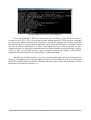
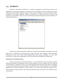
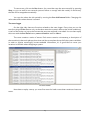
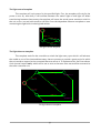
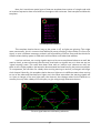
The UPPAAL template editor window
TRON is a tool that provides the testing capabilities we're looking for: it takes standard
UPPAAL models as an input and then, using a so-called adaptor, it connects to the target platform
and performs a real-time test. The adaptors themselves can be written either as an .DLL dynamic
libraries, or interface with TRON using TCP/IP [1].
1
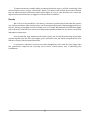
UPPAAL TRON while running an example test
Since we're offered a .NET API to interface with VeriStand, we've decided it was too
complex to use a C/C++ .DLL, so we wrote a simple adaptor based on TCP/IP and even managed
to interconnect TRON and VeriStand. Very early in testing this adaptor, we however found the
development process to be severely hindered by the fact that both UPPAAL and UPPAAL TRON
are closed systems distributed in a binary executable form only. Not being able to even
understand the inner workings, combined with the cumbersomeness of testing through a java to
TCP/IP to .NET to VeriStand interface, we've decided to drop all the adaptor writing efforts
altogether and instead develop our own, UPPAAL model based tester.
We will still use UPPAAL itself. In our case, it will be a great help to ease us of the burden of
writing a full-fledged timed automata editor ourselves, since the editor is now very mature and
stable. The relevant features present in UPPAAL and the format it stores the automata in will be
described in more detail in chapter 2.2.1.
2
2. Used concepts and technologies
2.1 Timed automata
Timed automatons are a core concept for this thesis, as our goal is to utilize them for
system descriptions. So we feel it is important to properly introduce and define them. Since timed
automata can be considered an extension of the so-called deterministic finite automatons
commonly found throughout computer science, let's begin by introducing these and later
describe the differences.
Deterministic finite automatons (DFAs)
Introduction
Automatons are a useful tool to describe systems that behave in a way that can be
expressed by a finite set of states and a description of possible transitions between them. To give
an informal real-world example, consider a simple light switch. The light can be either on or off
(giving us two states) and we can both turn the light off when it's on and vice versa (giving us
concrete rules or transition between the states).
turn light off
off
on
turn light on
An example automaton
In order to traverse between some states, we need a sequence of commands. In our
example, such commands are “turn light on” and “turn light off”. The picture describes how to
react to these commands, e.g. if we are in the off state, a “turn light on” command will set the
current state of the automaton to on.
The last important thing to note is, an automaton can be viewed as a directed graph, with
the nodes being all the automaton states, and edges being the transitions between them.
There are many different types of automatons, but we'll only concern ourselves with the
aforementioned discrete finite automaton.
3
Formal definition
Now that we have a general idea about automatons, let's define them formally. A
deterministic finite automaton A is a 5-tuple [2]:
A = (Q, Σ, δ, q0, F)
where
– Q is a set of states
– Σ is the input alphabet – the automaton processes a string of symbols from Σ
– δ is the transfer function, a subset of Q × Σ, that describes transitions as p = δ(q, a): p, q ∈
Q, a ∈ Σ meaning “if the current state is q and the symbol a is currently being read from
the input string, the next state of the automaton shall be q”
– q0 is the start state, q0 ∈ Q
– F is a set of accept states, F ⊂ Q: if the automaton reaches any of the states of F, It is said
to have accepted the input string
Timed automaton extensions
A timed automaton modifies the ordinary DFA by adding clocks to represent time flow and
by introducing several expressions to transitions. Formally, an automaton over a set of actions A
and a set of clocks C is defined [3] as a 4-tuple:
(A, C) = (L, l0, I, E)
where
–
–
–
–
L is a set of locations (basically equivalent to the Q state set of DFAs)
l0 is the initial location (again, much like a q0 in an DFA)
I is a set of invariants, assigning invariants to locations from L
E is a set of edges (transitions) between locations
furthermore, an edge is a 5-tuple
E = (l, g, a, r, l')
where
– l is the source location of the edge
– g is a guard, i.e. an expression that must be satisfied before taking the edge
– a is an action, either postfixed with “!” to denote an output action, or with “?” to denote an
input action
– r is a set of clocks to reset
– l' is the target location of the edge
4
Gone are the alphabet, transfer function and accepting states. The reason for this is that
formally, we use timed automatons to perform reachability analysis, to determine the reachable
locations by advanced queries. This topic is discussed in [3] and is tangential to our work. One can
use UPPAAL to perform this analysis and only then proceed to use the model with our system
tester.
UPPAAL extends this even further, offering a fully-featured scripting language on top of
these theoretical automata. To avoid redundancy, we're simply referring you to the next chapter,
where the most important extensions are described as a part of the model format.
Usage in modeling
Using timed automata for modeling real systems is straightforward: Define all the valid
states the system can be in (and that are important for the current testing scenario), then create
transitions between them and use transition conditions to limit execution flow.
A common occurrence is the controller-observer pair. We usually provide a set of controller
automata – their goal is to control the system and provide inputs to it, and a set of observer
automata, or observers. The observers only monitor the state of the system and check if it satisfies
some defined constraints. For real-world tests, observers can compare the virtual state (inside the
testing software) against the real one (gathered from the outputs of the system).
To test this system, we must now traverse the search space defined by all the automata in
the testing model. Since this space is very large and also even difficult to determine (thanks to
using clocks and a very flexible scripting language), to us, the only sensible method to do so is by
traversing the model randomly.
An example of a real-world usage of timed automata can be found in [4].
5
2.2 UPPAAL
2.2.1 System description using UPPAAL
In this chapter, we'll describe the formatting of UPPAAL system files. These are actually
valid XML documents with a clean, systematic structure. The XML element hierarchy of an
UPPAAL system is as follows:
nta
• declaration
• list of templates
• • name
• • declaration
• • list of locations
• • • id
•••x
•••y
• • init
• • • ref
• • list of transitions
• • • source
• • • target
• • • list of nails
• system
Formally, an UPPAAL system consists of:
– Global declarations (XML node nta/declaration)
Global declarations usually include all global variable declarations, and if no local
equivalent is defined inside a template, these are shared between all templates.
– System declarations (XML node nta/system)
The system declaration script is responsible for instantiating templates. The keyword
system is then used to specify which template instances are a part of the current system.
This provides a mechanism for switching various implementations of automata, we can for
example switch between different observer templates.
– Several (more than one for an actual system) templates (XML nodes nta/template)
6
A template consists of:
– A name (XML node nta/template/name)
Names are used as an identifier when instantiating templates.
– Local declarations (XML node nta/template/declaration)
This script specifies per-instance variables.
– Multiple locations (XML node nta/template/location)
A location is a state (node) of the associated timed automaton. Their name most likely
stems from the fact that they specify their on-screen location in the x and y parameters.
Locations are identified by their id parameter and can optionally also provide a userreadable sub-node called name. Lastly, locations can also have a label sub-node with its
kind parameter set to invariant. Invariant is a condition that must hold true when we are
in this specific location. Not satisfying this condition can be treated in different ways. In
our case, we'll use it as a trigger to fail the test.
– Initial location (XML node nta/template/init)
This XML node specifies (in its ref parameter) which of the automaton states is the default.
– Multiple transitions (XML node nta/template/transition)
If we consider the automaton to be a graph, then its nodes are the individual states and a
transition is then a directed edge between these states. It references a source and target
locations and can also specify a number of nail sub-nodes (once again with x and y
parameters) for display purposes.
This edge, however, also includes several traversal control mechanisms (all in a label subnode differentiated with the kind parameter):
– Synchronisation channel (“Sync”)
Any edge can either trigger or wait for a synchronisation event.
– Assignment (“Update”)
Contains a script to execute in the case the edge is taken while traversing the graph.
– Condition (“Guard”)
A condition that must be satisfied, otherwise the edge cannot be taken.
– Selection (“Select”)
Used to bind a variable to some range.
These features make use of the integrated scripting language.
7
2.2.2 An example system
Description
Let's provide an example of a timed automata using UPPAAL's extensions, just to
demonstrate their usage. In our early testing, we've modeled the behavior of a car's ignition
system in relation to the engine.
This system consists of two parts:
1. The key box.
We need to model the behavior of a key box. We'd like to simulate the key being inserted
and then turned, in a way that mimics the real-world behavior. A key box can thus be in
four distinct states:
– A key is not inserted into the box. This is the default state and means the car is not
operational and the electronics are either turned off or in a low-power state.
– A key is inserted in the key box. Function-wise, this is identical to the “key not present”
state.
– The key is turned to its stable position to the right. This turns on the electrical systems
in the car, preparing it to start the engine.
– We're turning the key further to the right. At this moment we've begun the process of
ignition of the engine and after a short time interval, the engine should start.
We also define one rule that applies to the transitions between these states. We cannot
skip over a state when advancing in either direction. For example, we can't go directly from
“engine starting” to “key not present”, unless there is a serious hardware failure. We can only go
to the directly adjacent states, as is the situation with the real-world system.
2. The engine
In our example, the engine will be in one of these states:
– Stopped.
– Starting. We're trying to start the engine by turning it electrically, in hopes of starting the
fuel burning cycle.
– Running. We've succeeded in starting the engine that now spins on its own.
The transition rules for the engine are obvious: we can't go from “stopped” to “running”
without starting the engine first, and we cannot return to “starting” once the engine is running,
we can only stop it.
8
Model design
Now we need to translate this description into an UPPAAL model. In a rather predictable
fashion, both the key box and the engine will have a separate template. Let's start by defining the
states. As we've got all the necessary states already figured out, let's simply assign them directly
to UPPAAL locations:
– For the key box template, the locations are no_key, key_in, key_active, key_turn
– For the engine template, the locations are stopped, starting, running
The transitions will correspond to the rules we've established, in the key box we'll
interconnect neighboring states in both ways. Also, we'll make loops in the key_active and
key_turn states. This will be explained later. In the engine, the transitions are as described:
stopped ⇔ starting, starting ⇒ running, running ⇒ stopped and also a loop around running.
So far, this could have been represented as one of the ordinary automata. Now the timebased extensions come to play. Let's begin with synchronisation channels. These are used to
synchronise events between multiple template instances. If, given a synchronisation channel
sync, one of the template instances goes through a transition that has its synchronisation
command set to sync!, the system must also go through exactly one valid transition with
synchronisation command set to sync? or not go through the sync! transition at all. This can be
used to synchronise different template instances as it forces one to update precisely when the
other one does.
We'll use three of these channels, to send commands from the key box to the engine.
The channels will thus be:
– Start ignition (start_ignition)
– Stop ignition (stop_ignition)
– Stop the engine (stop)
Now, let's introduce the concept of clocks. A clock is a channel, that represents time flow in
the system. Its most important property is that it updates automatically, and that all the clock
channels in a system update at the same constant rate. We can also assign values to clocks, this is
usually done to reset them to some initial value, in order to measure intervals in conditions.
We'll use one clock channel, ign_time, to measure the time we're holding the key in the
engine start position.
This leads us to the assign property of transitions. This property contains a simple script
that is executed whenever the transition is taken. We'll use this to reset the clock by setting this
property to “ign_time = 0” when we transition from key_active to key_turn.
9
The last concept is the guard property. Once again, it's a simple script, only this time it's
actually a Boolean expression that must be satisfied (true) before we can take the associated
transition. In our example, we'll simulate an engine that takes a minimum of two time units to
start. Before transitioning between starting and running, we must satisfy the condition
“ign_time > 2”, meaning the key must remain in the key_turn state for at least two time units.
We've designed the templates as such:
begin_ignition!
ign_time = 0
no_key
key_in
key_active
stop!
key_turn
stop_ignition!
The key box model
stop_ignition?
begin_ignition?
stopped
starting
ign_time > 2
running
stop_ignition?
stop?
The engine model
The global channels are defined with these lines:
clock ign_time;
chan begin_ignition;
chan stop_ignition;
chan stop;
We then describe the system with these commands:
eng = engine();
kbx = keybox();
system eng, kbx;
And that is all that is necessary to obtain a working example.
Note how, in the key box template, we use the loop transitions on the key_active and
key_turn states. We could have done this or all the states, but we don't really care about the first
two states, since they don't affect the engine in any way.
10
Also note that UPPAAL can deliberately wait in a state without doing anything. We've
reduced this behavior only to situations where no other option is available. To make the “stay in
current state” option viable to the decision engine, we explicitly state such a possibility with these
loop-around transitions.
To provide an example of the XML layout, the engine template looks like this:
<template>
<name>engine</name>
<location id="id4" x="120" y="-72">
<name x="110" y="-102">running</name>
</location>
<location id="id5" x="-120" y="-72">
<name x="-130" y="-102">starting</name>
</location>
<location id="id6" x="-352" y="-24">
<name x="-362" y="-54">stopped</name>
</location>
<init ref="id6"/>
<transition>
<source ref="id4"/>
<target ref="id4"/>
<label kind="synchronisation" x="80" y="-152">stop_ignition?</label>
<nail x="88" y="-128"/>
<nail x="152" y="-128"/>
</transition>
<transition>
<source ref="id5"/>
<target ref="id6"/>
<label kind="synchronisation" x="-240" y="-48">stop_ignition?</label>
<nail x="-144" y="-24"/>
</transition>
<transition>
<source ref="id4"/>
<target ref="id6"/>
<label kind="synchronisation" x="128" y="-24">stop?</label>
<nail x="120" y="72"/>
<nail x="-352" y="72"/>
</transition>
<transition>
<source ref="id5"/>
<target ref="id4"/>
<label kind="guard" x="-60" y="-102">ign_time > 2</label>
</transition>
<transition>
<source ref="id6"/>
<target ref="id5"/>
<label kind="synchronisation" x="-256" y="-96">begin_ignition?</label>
<nail x="-328" y="-72"/>
</transition>
</template>
11
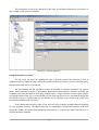
2.3 VeriStand
National Instruments VeriStand is a software package for performing real-time HIL
(Hardware-in-the-loop) simulations. It allows the user to describe a system consisting of various
data channels, execution models and also provides means to design a user interface (here called a
workspace). This logical software model is connected to a physical system via sensors and
actuators, allowing said system to be controlled and monitored, frequently with the intention of
performing tests on it.
VeriStand – Project Explorer
National Instruments provides a large array of input/output hardware, ranging from simple
digital I/O to industrial bus controllers (e.g. CAN, Controller Area Network). Some hardware
components even offer FPGA (Field-Programmable Gate Array) capability so that some
calculations or applications dependent on strict timing can be offloaded to the hardware.
Hierarchy of a VeriStand system
There are two parts of a VeriStand system – a system definition and a workspace. System
definition describes the hardware structure of the system: how many targets are we using and
what hardware is installed in them, the user-defined logical data channels, how these are mapped
to the actual hardware inputs and outputs. Another part of a system definition is information
regarding the real-time behavior of the system, one of the most important being the PCL
(Primary Control Loop) frequency. This value is the definitive time reference for the whole run-time
environment.
12
The workspace serves as an interface for the user. It facilitates observation and control of
any number of the system's channels.
VeriStand – system definition
Using VeriStand in our work
For our work, we won't be needing the user to directly control the channels, in fact, it
might even have a negative impact on the correctness of the test results in some cases. Therefore,
the workspace will not be of much use.
We will instead use the VeriStand system to provide an interface between our system
tester, which operates in terms of automaton states and synchronisation channels and the real
hardware unit, that can have an arbitrarily complex input / output interface. As we might simplify
our logical model of the unit, or even decide to focus on a specific part of it, we need to design the
VeriStand system to compensate for lost details and to perhaps wrap simple logic levels into
automaton variables and vice versa.
Given these requirements, most of the work will rely on either straight channel mapping
for the simplest systems, calculated channels for moderately complicated systems and even
execution models for cases when advanced computation is required to make interfacing to a
VeriStand system possible.
13
14
3. Implementation
The core part of this thesis is the implementation of a timed automata based system
verifier. We've named our program TASysTest for Timed Automata System Tester.
TASysTest was implemented in C#, allowing for nice and clean integration with the
VeriStand .NET API.
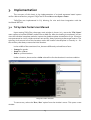
3.1 TA System Tester User Manual
Upon starting TASysTest, the empty main window is shown. In it, use to the “File / Open”
menu option to load the UPPAAL model from an XML file. After the loading is completed, you can
view the individual templates and also inspect the global template instantiation script. Locations
are represented as circles, while transitions are arrows, always pointing at the target location. The
spinning circle around one of the locations marks the location the template is currently in – for
this window, that always means the initial location.
In the middle of the transition's line, there are differently colored lines of text:
– Orange for guards.
– Green for updates
– Red for synchronisations
Under a location, there can be a violet-colored line for that location's invariant condition.
TASysTest main window
To start a test, select the “Run / Run” option from the window's menu. This opens a new
window.
15
Preparing a VeriStand project
Before we start any testing, we should prepare an accompanying VeriStand project to link
with our model. Doing that is simple: In our VeriStand system definition, prepare two folders
under “Aliases” named “in” and “out”. In these folders, create aliases for any VeriStand channel
you'd like to link with TASysTest and name it exactly the same as the corresponding variable in
your model's global variable space. The variables will then link automatically. Note that a variable
can be in both folders.
Now, with every tick during testing, TASysTest will read all the linked variables from the
“out” folder into its own variable store, then it will perform a valid step. After the step is finished,
TASysTest will update all the linked variables in the “in” folder with the values from its internal
variable store. Simply put, variables inside the “in” folder are written from TASysTest to VeriStand
and the variables in the “out” folder are written from VeriStand to TASysTest.
The run window
In this window, you should see all the template instances of the currently loaded system.
First, click on the Initialize VeriStand Adaptor button. You will be asked to point to the VeriStand
system definition file. The project must be already open in VeriStand. Now, the project will be
deployed on the target system. This might take a while. When this is done, the log (found under
the control buttons) will say “VeriStand adaptor started!” and the test controls will become
available.
Test run window
16
To start a test, click on the Run button. You can either stop the test manually by pressing
Stop, or you can wait for an eventual system's failure to comply with the model, in which case,
the test will be stopped automatically.
You can also select the tick period by moving the Run tick interval slider. Changing this
value takes effect when the test is started.
The trace logger
On the right side, there are functions related to the trace logger. Every time you run the
test (but using the Run button only, as that also resets the system's state to the initial conditions),
a trace of the entire run (up to the moment the test was stopped) is recorded. You can then replay
this trace with the Run Trace button, save and load the trace or view it.
The trace contains a series of events. Each event contains a timestamp, a description of
the transition(s) that took place at that time and also a complete dump of all the system variables.
In order to receive meaningful, human-readable information, it's a good idea to name your
locations in UPPAAL when designing a system.
The trace viewer
Note that to replay a trace, you must first record or load a trace that contains at least one
event.
17
3.2 TA System Tester Implementation
3.2.1 UPPAAL system parsing
The first necessary step for any system simulation is to actually open and parse the file in
which the system was defined. We've described the file format in chapter 2.2.1.
.NET offers robust XML parsing functions in the System.Xml namespace. The
XmlDocument class offers all the necessary functionality to read the system file. We provide the
TASystem.ParseSystemFromXML() function to do all the necessary loading.
Once loaded, the system is represented in a fashion closely following the UPPAAL XML,
with only some terminology changes. For run-time performance reasons, nodes also cache all the
outgoing edges that originate in it.
3.2.2 UPPAAL language parsing
On top of providing means to describe automata, UPPAAL implements a flexible scripting
language with C-like syntax. Since at least some parts of it are necessary to properly create a
working test environment, we have provided a parser and interpreter for said language. However,
UPPAAL's language is the result of many years of work, so we can't really provide a complete,
rigorous implementation. Instead, we'll only concern ourselves with a strict subset of this
language, based on our own needs and requirements. More details on this are further down this
chapter.
–
–
–
–
Given the system file structure, we need to support these constructs:
variable declarations
global / local variable scoping
template instantiations
expression evaluator
Variable declarations are imported in a straightforward way. We simply look if the source
code line begins with one of the known identifiers and then we consider the rest of the line (up
until the semicolon) to be the identifier:
<type> <ident>;
When instantiating templates, we must use this format:
<instance name> = <template name>({parameters});
Apart from handling parameters when instantiating templates, this is all that is required to
write rudimentary declaration scripts.
Also of note, the system keyword is actually ignored, instantiating is done just by the
scripts for individual instances. But to be compatible with UPPAAL, you still need to use the
keyword.
18
Lexing and parsing transition scripts
The scripts we use as parts of the transitions undergo a more complex process. Note that
any expression evaluation needs to first perform lexical analysis on the expression using a lexer,
splitting it into operators, operands and variable identifiers. After that, these tokens are fed to the
evaluator to provide an actual value to the program.
Since we're going to be interpreting these strings repeatedly, it is a good idea to perform a
lexer pass on them before starting the test. Our implementation does this, leaving all operators
and operands neatly separated with spaces. The evaluator, instead of doing a costly lexer pass,
can simply utilize a very simple tokenizer (in our case that means just using the .Split() method
with a parameter of a space character) to automatically gather all the necessary tokens, saving
time.
But we actually require to do a lexer pass anyway, because we need to deal with variable
scoping. UPPAAL models differentiate between template-local and global variables. Our pre-test
loader first instantiates all global variables. Then, when instantiating a template, also instantiates
all the local variables. Lastly, when processing individual scripts, looks whether the variable is
global or also exists as a local variant, and modifies the script to use the appropriate version. Once
again dropping the need to determine the variable scope at run-time.
The actual lexing is also done in a simple, yet efficient manner: using the .NET
String.Replace() method. Our strategy is to replace all operators with themselves, only with
spaces added to both before and after them. Since no valid script allows to have two operands
next to each other without an operator between them, this suffices.
Special care must be taken, however, when dealing with ambiguous operator pairs, such as
“=” and “==”, “!” and “!=”, et cetera. The safest approach is to simply replace the longer variants
with a special token beforehand and replacing them back after processing all the other operators.
As a final step, we remove all excess spaces that might have accumulated by the model
using spaces around operators in the first place.
Expression evaluation with the Shunting Yard algorithm
To solve the problem of evaluating expressions, we've programmed a version of the
relatively little-known Shunting Yard algorithm, as described in [5]. This algorithm was created in
1961 by Edsger Dijkstra and can be used to convert mathematical expressions from infix notation
to RPN (Reverse Polish notation) or an AST (abstract syntax tree). Alternatively, the formula can
be calculated on-the-fly, as in our case.
The algorithm works with two stacks (one for operands and one for operators) and reads
the input string on a per-token basis.
19
We also need to extend the functionality of the base algorithm further, to include support
for parentheses and variables. Variable support is provided by a simple rule: whenever an operand
is popped from the operand stack, if .NET's parser cannot convert the token to a number, assume
it's a variable and look it up.
The full algorithm works as follows:
Initialization:
– Prepare both stacks
– Determine operator precedences, that is, map an integer precedence value P(o) to all
operators (this can be done with a function or a look-up table).
– Left parenthesis must be treated as an operator with the lowest precedence!
Step:
– Read next input token t
– Is t an operand?
– Push it into the operand stack
– Is t an operator?
Given s is the operator on top of the operator stack:
– Repeat while P(s) ≥ P(t):
– Pop s
– Pop operands for s from the operand stack
– Perform calculation on the operands using s
– Push the result on the operand stack
– Push t on the operator stack
– Is t a right parenthesis?
Given s is the operator on top of the operator stack:
– Repeat while s ≠ left-paren:
– Pop s
– Pop operands for s from the operand stack
– Perform calculation on the operands using s
– Push the result on the operand stack
– Pop the left parenthesis from the operator stack
Final steps:
– Process all remaining operators as before:
– Pop s
– Pop operands for s from the operand stack
– Perform calculation on the operands using s
– Push the result on the operand stack
– Pop the final result from the operand stack
Operator precedences were taken from [6].
20
Differences from UPPAAL
Since we're only working with a small subset of the language, let's define the features we
do support.
– Operators
– Mathematical
– *
multiply
– /
divide
– +
add
– subtract
– >
bigger than
– <
lesser than
– >=
bigger than or equal
– <=
lesser than or equal
– ==
equal
– !=
not equal
– Logical
– &&
AND: both operands are nonzero
– ||
OR: at least one of the operands is nonzero
– Synchronisation channel operators
– !
perform the prefixed synchronisation
– ?
don't execute, unless the prefixed synchronisation takes place in this tick
– Expressions built using variable names and the operators listed above
– Variable types
– Channel (chan)
– Integer (int)
– Boolean (bool)
– Clock (clock)
– Edge operations
– Guards
– Assigns
– Synchronisation events
– Node invariants
We define that a TASysTest model is only valid if it is a valid UPPAAL model and uses only
the aforementioned features.
–
–
–
–
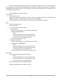
Most significant features absent from the full scripting language are: [7]
Arrays
Functions
Urgent channels
Structures
21
While not a part of the core language itself, notably missing is the whole querying feature.
Since queries are used for static reachability analysis, we feel that supporting this feature is
redundant, as one can do the static analysis directly in UPPAAL, if one feels this necessity. In
TASysTest, we instead try to traverse the search space randomly and in real-time, making this an
approach that is tangential to static analysis.
Also of note is, while UPPAAL doesn't define what failing a node invariant condition
means, we use this situation to actually determine the system has failed the test.
3.2.3 Runtime overview
Our runtime consists of the XML model loader and all the aforementioned script language
processing functions. Also present are adaptors, these classes serve as an interface between
TASysTest and some external automation system. We had VeriStand on mind when programming
the tester, but writing the engine like this should allow for easy porting to other systems.
When the runtime is first started, variables and templates are instantiated, and then script
preprocessing takes place. Then, the selected adaptor is started and after that, we are ready to
run the test.
Variable store
The tester contains a variable store. This is a data structure that contains all the variables
from both local and global scopes. To differentiate between them, each template instance is
assigned an integer identifier. This identifier is then used as a part of the prefix for local variables
of this instance. The identifiers start at 1, while the identifier 0 is reserved for global variables.
For example, let's assume we have a local variable lvar and a global variable gvar. We'll
have two instances of the same template that uses both of these variables.
Global declarations:
int gvar;
inst1 = template();
inst2 = template();
system inst1, inst2;
Template local declarations:
int lvar;
In this case, we'll end up with three variables: id0_gvar, id1_lvar and id2_lvar. Now let's
assume we have a transition that sets lvar = gvar. In the preprocessing step, this expression will be
converted to id1_lvar = id0_gvar (for the first instance). This allows us to address the variable store
directly with the variable name, without the concern we'll address the wrong one.
22
The edge picking algorithm used
Before we describe the algorithm, let's focus on synchronisation events. Synchronisation
events require special handling, as we can't simply treat edges that trigger them as viable choices
straight away. We need to make sure that this edge will also have a matching edge that waits for
this synchronisation (we'll call it sync-dependent). This makes the edge selection more
complicated, as we cannot simply pick a random edge. We need to handle this event matching
first.
We treat the sync-dependent edges to not be viable choices from the get go. Instead, we
only consider the sync-triggering edges, then remove ones that don't have a matching dependent
edge and if this triggering edge gets picked, we then select one of the dependent edges and
update it, too.
When running the test, we're doing a traversal of the model graph in a manner best
described by this algorithm:
– Prepare two edge lists: possible edges to take, possible sync-dependent edges to take
– For each template instance:
– For all outgoing edges of this instance's current node:
– If the edge contains a synchronisation script that waits for a synchronisation
(ends with a “?”), add it to the sync-dependent list and move to the next edge
– If the edge contains a guard expression, evaluate it. If the condition is satisfied,
add the edge to the possible to take list.
– Prepare a list of synchronisation channel names
– For all edges from the possible edge list:
– If the edge contains a synchronisation script that triggers a synchronisation (ends
with a “!”), add it to the channel name list – we cannot synchronise an edge pair if
there is no triggering edge
– For all edges in the sync-dependent list:
– If the edge's synchronisation channel is present in the channel list, add the edge to
the possible edge list
– From the possible edge list, pick an edge randomly and take it. Update the runtime state
using the assign property, if it is set.
– If the picked edge triggered a synchronisation, also randomly pick one of the dependent
edges and take it.
Running this algorithm once advances up to two template instances and is what
constitutes a discrete step. The whole testing run is simply a sequence of equidistant steps.
Trace logger
The trace logger simply records each step into a list of TraceLine objects. When working
with trace files, we utilize the .NET's XmlSerializer Class [8] to easily save and load all data in a
universal format.
23
3.2.4 Timing
Introduction
TASysTest assumes ideal timing conditions (all time units are equidistant and precise) that
cannot be satisfied by any real system. This chapter provides some explanations and specifies
how to deal with these inaccuracies.
First, an observation must be made about Windows – the operating system we use for our
implementation. Windows is by its nature a desktop OS, not a real-time OS. The difference is, a
real-time OS can guarantee a certain upper bound on response times, given a proper task
schedule. Windows provides no such guarantees. However, practice shows that some applications
can in fact work with soft real-time constraints. Take, as one example, various audio playback
applications. Such applications usually work with a constant buffer size that, coupled with the
fixed sampling rate of a soundcard, provides a concrete soft real-time task period. Failure to meet
the deadline creates an audible artifact (some parts of the sound can be repeated, or there are
clicks, depending on the behavior of the application should a buffer underrun occur). This simple
example shows that given certain conditions, real-time-like performance can in fact be achieved
with Windows. To better our chances of reaching such state, some precautions can be taken, like:
– Disabling all non-critical background services
– Setting either a “High” or “Realtime” priority for our process
– Not actually using the system during testing, specifically not launching any new
applications
– Disabling all power-saving options and screensavers
While taking these steps might not actually guarantee good real-time behavior, it
significantly improves the chances.
TASysTest does not attempt to correct the timing in any way. All testing is done in a besteffort fashion. We believe it's not really a problem, since there are always going to be inaccuracies
inherent to any testing, e.g. delays in communication between the tested system and TASysTest,
I/O port latencies, OS scheduler latencies, clock jitter, clock frequency instability or even nondeterministic behavior in the testing environment. Any real system will suffer, to a degree, from
non-ideal time domain behavior (when compared to the theoretical model) and there's nothing
that can be done about that.
What we consider important, though, is to provide a way to measure all the inaccuracies
by means of providing a trace log containing precise timestamps. Further analysis can be then
made, with some specific timing tolerance in mind, to determine if the outcome is close enough
for the user's needs.
24
The “Heartbeat” class
The “Heartbeat” class provides a precise, monotonic time source. It utilizes the
System.Diagnostics.Stopwatch class, that is based on the QueryPerformanceCounter() function
of the Win32 API. QueryPerformanceCounter() is considered to be the most accurate time source
available, as it reads the CPU's tick count directly. There are some small problems with this
approach, though. Some systems might have CPUs that don't synchronise tick counts between
individual cores. To remedy this situation, the user should set the program's affinity to the first
core only. Some CPUs might also underclock their core frequency under certain conditions. The
user should ideally forbid this behavior prior to testing. Setting the program's priority to High is
also possible, to further improve real-time performance in some cases.
Very detailed relevant information and also a method to detect both kinds of inaccurate
CPU behavior are described in [9].
3.2.5 VeriStand interface
To connect with VeriStand, National Instruments provides a .NET API split into several
libraries, most important of which is the NationalInstruments.VeriStand.ClientAPI [10]. This
library provides means to connect to VeriStand via the IWorkspace / IWorkspace2 classes and to
read and write variables directly from/to the running project. We use these methods of the
IWorkspace2 class:
ConnectToSystem()
DisconnectFromSystem()
GetAliasList()
GetSingleChannelValue()
SetSingleChannelValue()
Connects to VeriStand, deploys the selected
project to the target controller and runs it.
Disconnects from VeriStand.
Gets a list of all the variable aliases available in
the system definition. We use this to
automatically map all global variables to
VeriStand.
Gets a value of a single variable.
Sets a value of a single variable.
The biggest drawback is that VeriStand only offers polling-based reading, whereas an
event-driven interface would be more suitable for our scenario. To determine the performance of
this API, we've devised a simple measurement, presented in the chapter 4.2.
To assure proper behavior, TASysTest works in a read-execute-write fashion, meaning that
we first read all of the variables, only then we do all decision steps in our program and only after
that we write back all of the modified values back to VeriStand.
25
26
4. Experiments
4.1 Testing system
Overview
PXI system
CAN card
LAN
DAQ card
PC running
TASysTest
CAN
Car trailer
control unit
DAQ
connection
box
control
signals
lights
status
dummy load
resistors
The testing system block diagram
Our testing system consists of:
– A laptop PC with the following specifications:
– Operating system
Windows 7 Professional
– CPU
Intel core i5-3360M @ 2.80 GHz
– Memory
6 GB
– NI VeriStand version
2013
– .NET Framework version
4
– A NI PXIe-8135 controller with
– a NI PXI-6229 DAQ (Data Acquisition) card + a NI CB-68LPR connection terminal
– a NI PXI-8513 CAN card
– A VW car trailer control unit as the device under test
– A custom-made circuit board with resistors simulating the light bulbs of a car trailer and
also transistors used for level-shifting to provide signal level conversion for the trailer
control unit.
The PC is running both TASysTest and VeriStand. It communicates with the PXI system
over a dedicated Ethernet LAN connection. The PXI controller runs a project designed to translate
simple on/off signals to CAN messages the car trailer control unit can understand. It also checks
the status of individual dummy loads and converts them to 5V signals the DAQ card inside the PXI
controller can safely read.
The circuit board contains several power resistors to simulate both 5 and 21 watt-rated
light bulbs. Parallel to these are voltage dividers to create the 5V signal for the PXI. A part of these
dividers are LEDs connected in series to provide visual feedback.
27
5 W bulbs are simulated with 27 Ω resistors, resulting in a current of
V 12 V
I= =
=0.44 A
R 27 Ω
and power of
P=R⋅I 2=27 Ω⋅0.442 A=5.33W
21 W bulbs are simulated with 27 Ω resistors, resulting in a current of
V 12 V
I= =
=1.5 A
R 8Ω
and power of
P=R⋅I 2=8 Ω⋅1.52 A=18 W
The circuit used to simulate the light bulbs is as follows:
Trailer control unit
light power switch
(12V)
8Ω
or
27 Ω
350 Ω
to DAQ 5V input
150 Ω
Dummy resistive load (for simulating lights)
28
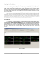
Our dummy load circuit board
A table of testing loads used:
light
power rating
reverse light
21W
brake lights
21W (2×)
fog light
21W
tail light (L)
5W
tail light (R)
5W
turn light (L)
21W
turn light (R)
21W
LED color
green
red
green
red
red
yellow
yellow
The trailer control unit itself behaves as a CAN-controlled light switch containing a
controller and power switching transistors.
+12 V
CAN high
CAN low
brake signal
power on signal
GND
9, 11, 12
7
8
3
2
10
Trailer
control
unit
3
13
2
10
4
5
7
reverse light
brake lights
fog light
tail light (L)
tail light (R)
turn light (L)
turn light (R)
The trailer control unit block diagram
29
To convert PXI's 5V digital outputs to 12 V the trailer control unit uses, level-shifting
circuits are employed:
+12 V
1.8 kΩ
12V output
5V input
BS170
5 V to 12 V NMOS-based level shifter
4.2 Determining VeriStand .NET API's realtime performance
As was discussed in the chapter 3.2.4, TASysTest has some assumptions about the timing
behavior. Since we cannot correct for the inherent inaccuracies, we need to at least determine
how close to the ideal situation can we get. We've designed a measurement experiment to
determine the performance of the provided VeriStand .NET API in a busy-loop polling scenario.
To measure the timing performance, we're going to create a VeriStand system to be run on
the hardware target system. The system will run a model that will increase a value of a variable by
one each primary control loop tick. We will then monitor changes to said variable on our Windows
system. We will measure:
– The exact timestamp of all “variable change” events
– How many times was the previous value read before it changed
(to determine possible overhead)
– What is the difference between the current and previous value
(to determine lagging)
Ideally, we'd like to see many repeats and all value differences to be 1. Repeats would
mean we've read the same value multiple times, therefore our busy loop is working several times
faster than the VeriStand API can provide new values.
On the other side, value differences > 1 would mean that between two successive reads,
we have missed a primary control loop tick and therefore have no information about the state the
system was in during this time.
For our testing, the VeriStand PCL was set to 1000 Hz, meaning we should ideally read
back 1000 unique values each second.
30
Results
Measurement 1
As the measured data suggest, the API caches all variable values, updating them each
66ms, or at 15 Hz. This was later confirmed by [11]. After the system stabilizes, this behavior is
stable and the values are repeated often enough, though the PCL frequency is very low, so this
behavior is to be expected.
However, this read rate is perhaps too low for some practical applications, so we'd like to
find a way to increase it, preferably to be in sync with the PCL.
Repeats between reads
repeats 90
80
70
60
50
40
30
20
10
0
0,00
1,00
2,00
3,00
4,00
5,00
6,00
time [s]
At 15Hz, data is repeated between reads
Setting the correct data rate
To increase the value read rate, we can manually edit the system definition file (.nivssdf) as
suggested by [12].
The system definition file is a standard XML file. The node Root/TargetSections/Target/Properties
contains the following property:
<Property Name="Data Rate">
<Double>15</Double>
</Property>
that can be changed to the desired read frequency in Hz.
31
Measurement 2 with the correct data rate
After setting the data rate to 1000 Hz (same as the PCL), the behavior changed
accordingly. Unfortunately, the measurements show that the busy loop cannot keep up with the
PCL, as most of the reads skip several PCL cycles. Given that some extreme skip values are just
manifestations of services running in the background (that were not turned off, and are thus
preventable), the busy-loop seems to be usable for reading values in about 4ms periods, or at 250
Hz.
Skips between reads
skips
10
9
8
7
6
5
4
3
2
1
0
0,00
0,20
0,40
0,60
0,80
1,00
At 1 kHz, some values are skipped
32
1,20
1,40
1,60
time [s]
4.3 Testing a car trailer controller unit
Experiment overview
Our real-world test cases will be centered around testing the trailer control unit. When
putting together the corresponding VeriStand model, implementing the CAN communication and
testing the overall behavior of the unit, we've discovered that different lights have different on/off
state change latencies. In our first test, we'd like to determine the tolerances required to assure
stable operation.
In this test, we'll showcase template reusability within UPPAAL models. We'll have the
same set of controller – observer template instances for all of the individual lights.
Our measurement strategy will be as follows:
– We'll be randomly turning lights on and off.
– In the model, we'll define a certain timing tolerance for each individual light switch.
– We will then successively lower this tolerance on a per-light basis in a set interval, until
such time will be found, that the light will fail to react in time and cause an invariant to
not be satisfied within an observer template instance.
– To determine this time with a sufficient accuracy, edge case measurements will be run
for at least three minutes.
This shall provide a table of absolute minimum allowable time tolerances for every light.
Based on rough observation, we expect the turn signals to require the biggest tolerance, and the
brake lights to require the smallest one.
System model design
Our model will be composed of three templates: one for power control, one for controlling
a light and one for observing its behavior. The light templates will be parametric, so we can reuse
them for all of the light switches and execute them in parallel.
The power control template
This template is very simple – its only job is to turn the power to the unit on, before all
other testing can be done.
power = 1
The power control template
33
The light control template
This template will cycle power for the specified light. First, the template will wait for the
power to turn on, after that, it will oscillate between two states: light on and light off. When
transitioning between these states, the template will cause the actual power transistor switch in
the unit to turn on and said transition will also force the dependent observer template to start
monitoring the light bulb simulating load resistor.
power == 1
turn_off!
simstate = 0
turn_on!
simstate = 1
The light control template
The light observer template
This template waits for the controller to switch the light state, upon which it will advance
the model to one of the intermediate states, that are present to provide a grace period in which
the unit needs to respond to the command that was sent to it. To implement this, we'll introduce a
clock channel named main, which will be set to zero at the exact time we send the command to
the trailer controller unit.
main > 5
actstate == 1
turn_on?
main = 0
turn_on?
main = 0
turn_off?
main = 0
main > 5
actstate == 0
turn_off?
main = 0
The light observer template
34
Only after this clock reaches a certain time threshold, it will be allowed to advance to a
state that will measure if the actual light bulb is glowing or not (represented by the variable
actstate that VeriStand will provide with each tick). This is done by setting the appropriate state's
invariant to be either 0 or 1, for the cases when the light should be off or on, respectively. The
unit's failure to change states quickly enough might cause the model to advance to the
measurement state (controlled by the measurement PC's timing) sooner than it changed the light
state.
To put everything together, we'll instantiate the controller template for each light. Note
that we only need to observe one light at a time. We will then decrease the timing tolerance from
a safe value down to such value that the system will fail the timing constraints, record this value
and move on to the next light, until all of the time tolerances are determined.
Results
First of all, we've determined that for multiple variables, VeriStand must be interfaced with
at a lower rate, otherwise the API will simply fall behind, cache all the variable writes and then
execute them in order, but with severe latency. Our tests found 20 Hz to be the optimum.
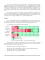
The following tolerances, in system ticks, were measured:
Tail light (L)
0 1
2 3 4 5 6
7 8 9 10 11 12 13 14 15 16 17 18 19 20
Tail light (R)
0 1
2 3 4 5 6
7 8 9 10 11 12 13 14 15 16 17 18 19 20
Turn light (L)
0 1
2 3 4 5 6
7 8 9 10 11 12 13 14 15 16 17 18 19 20
Turn light (R)
0 1
2 3 4 5 6
7 8 9 10 11 12 13 14 15 16 17 18 19 20
Brake light
0 1
2 3 4 5 6
7 8 9 10 11 12 13 14 15 16 17 18 19 20
Reverse light
0 1
2 3 4 5 6
7 8 9 10 11 12 13 14 15 16 17 18 19 20
Fog light
0 1
2 3 4 5 6
7 8 9 10 11 12 13 14 15 16 17 18 19 20
Tolerance too low
Tolerance big enough
More pronounced colors signify values that were actually tested
Since we've used a tick frequency of 20 Hz, that gives us a tick period of 50 ms. Our model
used a strict inequality operator for its tick count comparisons, therefore we need to increase the
tick count for the final time value calculation by one.
Adjusted for this, these final timing requirements are:
– Both tail lights, the fog light and the reverse light require at most 250 ms to stabilize.
– Both turn lights require at most 750 ms to stabilize.
– The brake light requires at most 50 ms to stabilize.
35
4.4 Extended controller unit specification
Experiment overview
Just for the sake of providing a testing scenario that is closer to what a real-world use-case
could look like, we shall introduce some higher-level functionality constraints. Let's assume our
unit passed the first experiment (given proper timing tolerances of course), and we'd like to
perform an integration test, that is, observe the unit in a more spread-out system involving other
independent units. Note that failing such test can mean the unit itself operates fine, but other
parts of the system are failing to work properly.
Our test will assume (but still check) a working unit, that is a part of a bigger system which,
to pass, needs to work with individual lights on a slightly higher level than just considering them
to be all independent.
Take for example the turning indicators. In a real car, these can have two functions: one of
them can blink to indicate a left or right turn, or they can blink both at once to signal a warning.
Now, our test should, for example, check that if both turning lights are on, we are actually in a
“signal warning” state. Otherwise, the behavior is incorrect.
System model design
This model will consist, at least from a certain point of view, from three layers:
– A high-level function controller
This layer will randomly switch these functions on and off:
– Gearbox put in reverse gear
– Fog lights on
– Signal turning left
– Signal turning right
– Signal warning
– Signal braking
– Low-level light switching
– This layer's job is to take these high-level commands and convert them to basic light
switch commands as in the previous experiment. For practical reasons, the high-level
templates will actually do the switching, since doing so in a separate template would
only introduce a pair of synchronisation channels directly linked to physical outputs.
This only unnecessarily adds complexity and can be done directly in the related
transition's assign property.
– Behavior observing
– This layer will check if the high-level model corresponds with the low-level behavior. In
the previous experiment, we used a simple invariant checking whether the light is on
or off. This time, we'll use more complex expressions to correctly express the
requirements stated in the introduction.
36
Most of the high-level functions are still on/off only, so we'll reuse our light control
template as a generic controller:
power_status >= 1
off!
simstate = 0
on!
simstate = 1
A generic switching template
A slightly extended version that controls both lights at the same time is introduced for the
tail lights.
The turn signal logic however requires to distinguish between three mutually exclusive
states: turning left, turning right and warning.
power_status >= 1
turn_change!
sim_turn_l = 1
turn_change!
sim_turn_r = 1
turn_change!
sim_turn_l = 0
turn_change!
sim_turn_r = 0
warning_off!
sim_turn_l = 0, sim_turn_r = 0
warning!
sim_turn_l = 1, sim_turn_r = 1
The turn signals control template
37
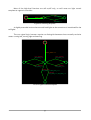
Now, let's introduce a special type of observer template that consists of a single node with
an invariant expression that must hold true throughout the entire test. One example would be this
template:
(power_status == 0
&& tail_l == 0
&& tail_r == 0
&& turn_l == 0
&& turn_r == 0
&& fog == 0
&& brake == 0
&& reverse == 0)
|| power_status == 1
The “always-true” observer
This template checks that as long as the power is off, no lights are glowing. This might
seem unnecessary, but it's common that additional power switching is done either in a form of a
signal, or even a software message, so there's still a possibility of failure. One could also think of a
scenario where backup power is used and could introduce such behavioral oddities.
Last but not least, our turning signals require a bit more complicated observer as well. We
need to check, as was mentioned, that the only time both turn signals are on is when we are in a
“signal warning” state. This could have been done with an “always-true” observer as well, but
there is still a slight problem: the latencies demonstrated and measured in the previous example.
To compensate, we will allow for a delay when turning warning on and off, once again utilizing a
clock channel. Basically, this template checks that turn lights are in a different state when turning
to one of the sides and that both turn lights are in the same state when the warning signals are
on. Upon a change of the turn light state, the observer also changes what kind of behavior to
monitor, but only after a delay of 20 ticks pass, to give a big enough tolerance timeout.
power_status >= 1
turn_change?
main = 0
warning?
main = 0
(turn_l != turn_r)
|| ((turn_l + turn_r) == 0)
main > 20
main > 20
turn_l == turn_r
warning_off?
main = 0
main > 20
The turn signal observer with latency tolerance
38
To demonstrate this model's ability to detect behavioral errors, we'll be introducing CAN
communication errors using a “CAN break” device. This device shall induce errors that will leave
the unit without proper information about which lights to turn on, that should in turn cause the
high-level function observers to trigger an invariant failure condition.
Results
We've first run the model as is for about 5 minutes to confirm that it describes the system
in a working condition. After checking this, we've started modifying the CAN messages directly on
the bus, forcing some lights to have a constant on or off state. We randomly tried different lights
and in all cases, when left for a certain time beyond the specified tolerance, our tester successfully
indicated a system error.
As a second test, that would provide similar results, we've tried disconnecting all the light
monitor signals from the PXI. Once again, given sufficient time, the tester recognized this as a
failure to comply with the specified model.
In conclusion, whenever a serious error that changed the unit's state for time longer than
the specification required has occurred, we've had a 100% success rate in detecting this
misbehavior.
39
40
5. Conclusion
5.1 Summary of work done
In this work, we've analyzed the possibilities of using timed automata, UPPAAL and
UPPAAL TRON for on-line system testing. After deeming TRON unsuitable, we've went on to
create our own testing environment from scratch. Then we have successfully implemented this
environment in C# and prepared and ran some experiments to test it on a simple real-world
example. The testing environment was proven to be working and able to detect incorrect
behavior of the system under test.
5.2 Experiment results
The first experiment determined that VeriStand's .NET interface can be reliably used for
speeds up to about 250 Hz when running under ideal conditions and working with a single
variable.
Our second experiment determined the timing characteristics of the measured car trailer
control unit. For the tail lights, fog light and the reverse light the maximum measured time
required for the unit to change their power status was 250 ms. For both turn lights, the time
required was 750 ms and for the brake light, the required time was 50 ms.
Additionally, it gave us the more realistic 20 Hz rate for interfacing with VeriStand.
The third experiment confirmed the tester's ability to detect 100 % of the errors, given
enough time for them to manifest themselves.
5.3 Proposed modifications to timed automata
The theoretical concept of timed automata, in the way UPPAAL works with it, proved to
be a neat way of describing and testing systems. However, there were times where we felt this
notation to be too constraining and/or inexpressive for practical testing scenarios.
We'd like to present some of the possible alterations to timed automata to make them
more suitable for real-world testing (but conversely, making them stray from the existing UPPAAL
format and forming a new one instead):
Parallel execution of template instances
Introduce the possibility to specify template instances that are forced to update with every
tick, or with a period of n ticks. While this might seem to cause problems, especially with
synchronisation, in reality the worst-case scenario is that there is no next edge to take.
41
Care would have to be taken to not over-use this feature, as running everything in parallel
might cause the system under test to not be able to traverse through all possible states, but only a
subset of them, just because the model is forced to update.
Probability-based edge picking
In order to test different states, it would be also nice to have a way of not revisiting the
previously visited states, or at least do so with smaller probability. Edges would have either a
static probability, a dynamically updated probability (based on the number of times it was taken),
or a combination of both. The edge picker would then consider these when choosing an edge.
Even more complex system would also combine this with the combinations of states all
the template instances are and were in.
Multi-synchronistion channels
A useable feature would be a special type of synchronisation channel, that would cause
not one, but all dependent edges to be taken at the same time. It could either be a special
property of the edge, or signified by a different trigger operator (e.g. “!!” instead of “!”).
Forced-traversal guards
The guard conditions of an edge work in a way that the edge may be taken, if the
condition evaluates to true. An additional guard type that would change this behavior to must be
taken. This would provide a mechanism for the system under test to generate synchronisations, in
contrast to the fact that synchronisations are now internal to the tester. A simple transition with
both this force-guard and a synchronisation trigger would work like this. Once again, proper care
when designing the model would have to be taken, as a situation where two of the outgoing
edges both have force-guards that are not mutually exclusive might occur. The runtime should
then detect this case and stop the test at that point.
42
5.4 Further work
Here are a few ways how one can improve this tester:
– A script compiler
As of now, the scripts are re-parsed (to an extent) and interpreted every time they are
used. Make a simple script compiler targeting either some custom virtual machine or
even native code (although this would probably turn out to not be that effective in
.NET). Extend the edges to instead point to this intermediate code and execute it on
demand.
– VeriStand-integrated test engine
For scenarios where fast response times are required, port the runtime directly into
VeriStand, with the models either still in XML, or some pre-compiled form. Running
the tester directly on the controller shall provide superior performance and would
solve most of the problems that arise from communicating with the controller over
TCP/IP from a Windows desktop computer.
– Integrating a system model designer
As of now, UPPAAL is the design tool. Write a custom designer interface. This step
might be necessary, should one decide to also provide some compatibility-breaking
features.
– Extending the tester with different adaptors
– Better UPPAAL compatibility
That means both supporting more UPPAAL features and also making sure the systems
are compatible with each other. Scripts and arrays would be particularly useful.
– Implementing some of the proposed features
Alternatively, from the proposed modification list, carefully consider and implement
some or all of the extension to timed automata. This will, however, break UPPAAL
compatibility! That might or might not be a desired step.
43
44
References
[1]
K.G. Larsen, M. Mikučionis, B. Nielsen. Uppaal Tron User Manual.
Aalborg: Aalborg University, 2009.
[2]
J.E. Hopcroft. Introduction to automata theory, languages, and computation. 2nd ed.
Boston: Addison-Wesley, 2001. ISBN 02-014-4124-1.
[3]
F. Stenh. Extending a Real-Time Model-Checker to a Test-Case Generation Tool
Using libCoverage. 2008.
[4]
K.G. Larsen, M. Mikučionis, B. Nielsen, A. Skou. Testing Real-Time
Embedded Software using UPPAAL-TRON: An Industrial Case Study.
Aalborg: Aalborg University, 2005.
[5]
Reed, Nathan. The Shunting-Yard Algorithm [online]. December 2011.
http://www.reedbeta.com/blog/2011/12/11/the-shunting-yard-algorithm/
[6]
Precedence and Order of Evaluation. MSDN [online]. Microsoft.
http://msdn.microsoft.com/en-us/library/2bxt6kc4.aspx
[7]
UPPAAL Help
http://www.uppaal.com
[8]
XmlSerializer Class. MSDN [online]. Microsoft.
http://msdn.microsoft.com/en-us/library/system.xml.serialization.xmlserializer.aspx
[9]
Acquiring high-resolution time stamps. MSDN [online]. Microsoft.
http://msdn.microsoft.com/en-us/library/windows/desktop/dn553408.aspx
[10]
NI VeriStand™ .NET API Help. [online] National Instruments 2012.
http://zone.ni.com/reference/en-XX/help/372846D-01/vsnetapis/bp_vsnetapis/
[11]
Understanding the VeriStand Engine. [online] National Instruments 2012.
http://zone.ni.com/reference/en-XX/help/372846G-01/veristand/understanding_vs_engine/
[12]
NI Discussion Forums: Gateway channel caching? [online]
http://forums.ni.com/t5/NI-VeriStand/Gateway-channel-caching/td-p/2602087
45
46
Appendices
Included CD contents
– TASysTest
– Contains the binary distribution and the complete source code of TASysTest.
– TASysTest models
– Contains system models used as an example or in our testing.
– VeriStand Timing Test
– Contains both the source code to the testing utility and the VeriStand model for the
experiment “Determining VeriStand .NET API's realtime performance”.
– VeriStand Trailer Passthrough
– Contains a VeriStand project to be used for both trailer control unit experiments. This
project simply copies its inputs to outputs and represents an ideal control unit with
zero response times
– In the CD's root, there's a complete pdf version of this thesis.
Appendix A
VeriStand API realtime performance measurement: 15Hz case
20,43150113:
20,43960287:
20,44906433:
20,51487295:
20,58107305:
20,64812068:
20,71613544:
20,78177932:
20,84768371:
20,91335365:
20,97901772:
21,04568891:
21,11299886:
21,17925400:
21,25841241:
21,32568274:
21,39086068:
21,45680799:
21,52324730:
21,58953436:
21,65477980:
21,72077921:
21,78677568:
21,85293836:
21,91925330:
21,98752561:
22,05301467:
22,12057888:
22,18646859:
22,25304036:
22,31927384:
22,38527142:
22,45095897:
22,51724859:
22,58337458:
22,64903718:
22,71533487:
22,78164027:
22,84713373:
VSIF: deployed system
new value: 00002970, last
new value: 00003036, last
new value: 00003102, last
new value: 00003168, last
new value: 00003234, last
new value: 00003300, last
new value: 00003366, last
new value: 00003432, last
new value: 00003498, last
new value: 00003564, last
new value: 00003630, last
new value: 00003696, last
new value: 00003762, last
new value: 00003828, last
new value: 00003894, last
new value: 00003960, last
new value: 00004026, last
new value: 00004092, last
new value: 00004158, last
new value: 00004224, last
new value: 00004290, last
new value: 00004356, last
new value: 00004422, last
new value: 00004488, last
new value: 00004554, last
new value: 00004620, last
new value: 00004686, last
new value: 00004752, last
new value: 00004818, last
new value: 00004884, last
new value: 00004950, last
new value: 00005016, last
new value: 00005082, last
new value: 00005148, last
new value: 00005214, last
new value: 00005280, last
new value: 00005346, last
new value: 00005412, last
reading
reading
reading
reading
reading
reading
reading
reading
reading
reading
reading
reading
reading
reading
reading
reading
reading
reading
reading
reading
reading
reading
reading
reading
reading
reading
reading
reading
reading
reading
reading
reading
reading
reading
reading
reading
reading
reading
repeated
repeated
repeated
repeated
repeated
repeated
repeated
repeated
repeated
repeated
repeated
repeated
repeated
repeated
repeated
repeated
repeated
repeated
repeated
repeated
repeated
repeated
repeated
repeated
repeated
repeated
repeated
repeated
repeated
repeated
repeated
repeated
repeated
repeated
repeated
repeated
repeated
repeated
47
0000
0006
0058
0060
0058
0054
0057
0065
0059
0064
0071
0078
0079
0074
0071
0071
0080
0079
0081
0080
0077
0079
0080
0080
0073
0078
0079
0076
0077
0079
0078
0079
0078
0079
0077
0078
0079
0077
times,
times,
times,
times,
times,
times,
times,
times,
times,
times,
times,
times,
times,
times,
times,
times,
times,
times,
times,
times,
times,
times,
times,
times,
times,
times,
times,
times,
times,
times,
times,
times,
times,
times,
times,
times,
times,
times,
diff=2970
diff=66
diff=66
diff=66
diff=66
diff=66
diff=66
diff=66
diff=66
diff=66
diff=66
diff=66
diff=66
diff=66
diff=66
diff=66
diff=66
diff=66
diff=66
diff=66
diff=66
diff=66
diff=66
diff=66
diff=66
diff=66
diff=66
diff=66
diff=66
diff=66
diff=66
diff=66
diff=66
diff=66
diff=66
diff=66
diff=66
diff=66
22,91357635:
22,97948220:
23,04566212:
23,11206548:
23,17737990:
23,24361522:
23,30924150:
23,37511470:
23,44139295:
23,50731201:
23,57330995:
23,63914059:
23,70565622:
23,77096587:
23,83693336:
23,90341156:
23,96903197:
24,03589028:
24,10131256:
24,16765025:
24,23354399:
24,29885768:
24,36492569:
24,43126925:
24,49715969:
24,56345445:
24,62938232:
24,69565910:
24,76091078:
24,82714830:
24,89315762:
24,95966737:
25,02547747:
25,09089975:
25,15832124:
25,22463618:
25,29030392:
25,35622664:
25,42268467:
25,48793672:
25,55446996:
25,62156785:
25,68714533:
25,75366096:
25,81964019:
25,88556585:
25,95135833:
26,01768574:
26,08311207:
new
new
new
new
new
new
new
new
new
new
new
new
new
new
new
new
new
new
new
new
new
new
new
new
new
new
new
new
new
new
new
new
new
new
new
new
new
new
new
new
new
new
new
new
new
new
new
new
new
value:
value:
value:
value:
value:
value:
value:
value:
value:
value:
value:
value:
value:
value:
value:
value:
value:
value:
value:
value:
value:
value:
value:
value:
value:
value:
value:
value:
value:
value:
value:
value:
value:
value:
value:
value:
value:
value:
value:
value:
value:
value:
value:
value:
value:
value:
value:
value:
value:
00005478,
00005544,
00005610,
00005676,
00005742,
00005808,
00005874,
00005940,
00006006,
00006072,
00006138,
00006204,
00006270,
00006336,
00006402,
00006468,
00006534,
00006600,
00006666,
00006732,
00006798,
00006864,
00006930,
00006996,
00007062,
00007128,
00007194,
00007260,
00007326,
00007392,
00007458,
00007524,
00007590,
00007656,
00007722,
00007788,
00007854,
00007920,
00007986,
00008052,
00008118,
00008184,
00008250,
00008316,
00008382,
00008448,
00008514,
00008580,
00008646,
last
last
last
last
last
last
last
last
last
last
last
last
last
last
last
last
last
last
last
last
last
last
last
last
last
last
last
last
last
last
last
last
last
last
last
last
last
last
last
last
last
last
last
last
last
last
last
last
last
reading
reading
reading
reading
reading
reading
reading
reading
reading
reading
reading
reading
reading
reading
reading
reading
reading
reading
reading
reading
reading
reading
reading
reading
reading
reading
reading
reading
reading
reading
reading
reading
reading
reading
reading
reading
reading
reading
reading
reading
reading
reading
reading
reading
reading
reading
reading
reading
reading
repeated
repeated
repeated
repeated
repeated
repeated
repeated
repeated
repeated
repeated
repeated
repeated
repeated
repeated
repeated
repeated
repeated
repeated
repeated
repeated
repeated
repeated
repeated
repeated
repeated
repeated
repeated
repeated
repeated
repeated
repeated
repeated
repeated
repeated
repeated
repeated
repeated
repeated
repeated
repeated
repeated
repeated
repeated
repeated
repeated
repeated
repeated
repeated
repeated
48
0080
0079
0079
0079
0077
0079
0078
0079
0079
0079
0079
0079
0079
0076
0079
0078
0079
0080
0078
0076
0079
0078
0078
0079
0079
0079
0080
0079
0079
0078
0079
0079
0079
0080
0081
0080
0080
0079
0080
0080
0076
0073
0077
0079
0079
0076
0079
0079
0078
times,
times,
times,
times,
times,
times,
times,
times,
times,
times,
times,
times,
times,
times,
times,
times,
times,
times,
times,
times,
times,
times,
times,
times,
times,
times,
times,
times,
times,
times,
times,
times,
times,
times,
times,
times,
times,
times,
times,
times,
times,
times,
times,
times,
times,
times,
times,
times,
times,
diff=66
diff=66
diff=66
diff=66
diff=66
diff=66
diff=66
diff=66
diff=66
diff=66
diff=66
diff=66
diff=66
diff=66
diff=66
diff=66
diff=66
diff=66
diff=66
diff=66
diff=66
diff=66
diff=66
diff=66
diff=66
diff=66
diff=66
diff=66
diff=66
diff=66
diff=66
diff=66
diff=66
diff=66
diff=66
diff=66
diff=66
diff=66
diff=66
diff=66
diff=66
diff=66
diff=66
diff=66
diff=66
diff=66
diff=66
diff=66
diff=66
VeriStand API realtime performance measurement: 1000Hz case (first 202 ms)
18,54012955:
18,54618293:
18,54788275:
18,55023967:
18,55164671:
18,55289855:
18,55409903:
18,55525694:
18,55644531:
18,55769642:
18,55892735:
18,56012122:
18,56120393:
18,56229910:
18,56337740:
18,56539495:
18,56703570:
18,56868819:
18,57039058:
18,57183210:
18,57344864:
18,57502371:
18,57665749:
18,57838115:
18,57986891:
18,58147664:
18,58325901:
18,58514851:
18,58688245:
18,58859694:
18,59036684:
18,59209784:
18,59383985:
18,59542997:
18,59683334:
18,59883585:
18,60069857:
18,60246002:
18,60421891:
18,60564833:
18,60727477:
18,60859412:
18,61026238:
18,61207300:
18,61374494:
18,61553978:
18,61737352:
18,61920248:
18,62091734:
18,62261019:
18,62436871:
18,62583299:
18,62738311:
18,62920584:
18,63067708:
18,63257723:
18,63434565:
18,63578278:
18,63749030:
18,63906317:
18,64066466:
18,64234100:
18,64377299:
18,64543722:
18,64692094:
18,64847803:
18,65042184:
18,65221741:
18,65352576:
18,65504727:
18,65667334:
18,65831409:
VSIF: deployed system
new value: 00080263, last
new value: 00080267, last
new value: 00080269, last
new value: 00080271, last
new value: 00080272, last
new value: 00080273, last
new value: 00080275, last
new value: 00080276, last
new value: 00080277, last
new value: 00080278, last
new value: 00080279, last
new value: 00080281, last
new value: 00080282, last
new value: 00080283, last
new value: 00080285, last
new value: 00080286, last
new value: 00080288, last
new value: 00080290, last
new value: 00080291, last
new value: 00080293, last
new value: 00080294, last
new value: 00080296, last
new value: 00080298, last
new value: 00080299, last
new value: 00080301, last
new value: 00080303, last
new value: 00080304, last
new value: 00080306, last
new value: 00080308, last
new value: 00080310, last
new value: 00080311, last
new value: 00080313, last
new value: 00080315, last
new value: 00080316, last
new value: 00080318, last
new value: 00080320, last
new value: 00080322, last
new value: 00080324, last
new value: 00080325, last
new value: 00080327, last
new value: 00080328, last
new value: 00080330, last
new value: 00080331, last
new value: 00080333, last
new value: 00080335, last
new value: 00080337, last
new value: 00080339, last
new value: 00080340, last
new value: 00080342, last
new value: 00080344, last
new value: 00080345, last
new value: 00080347, last
new value: 00080349, last
new value: 00080350, last
new value: 00080352, last
new value: 00080354, last
new value: 00080355, last
new value: 00080357, last
new value: 00080358, last
new value: 00080360, last
new value: 00080362, last
new value: 00080363, last
new value: 00080365, last
new value: 00080366, last
new value: 00080368, last
new value: 00080370, last
new value: 00080372, last
new value: 00080373, last
new value: 00080374, last
new value: 00080376, last
new value: 00080378, last
reading
reading
reading
reading
reading
reading
reading
reading
reading
reading
reading
reading
reading
reading
reading
reading
reading
reading
reading
reading
reading
reading
reading
reading
reading
reading
reading
reading
reading
reading
reading
reading
reading
reading
reading
reading
reading
reading
reading
reading
reading
reading
reading
reading
reading
reading
reading
reading
reading
reading
reading
reading
reading
reading
reading
reading
reading
reading
reading
reading
reading
reading
reading
reading
reading
reading
reading
reading
reading
reading
reading
repeated
repeated
repeated
repeated
repeated
repeated
repeated
repeated
repeated
repeated
repeated
repeated
repeated
repeated
repeated
repeated
repeated
repeated
repeated
repeated
repeated
repeated
repeated
repeated
repeated
repeated
repeated
repeated
repeated
repeated
repeated
repeated
repeated
repeated
repeated
repeated
repeated
repeated
repeated
repeated
repeated
repeated
repeated
repeated
repeated
repeated
repeated
repeated
repeated
repeated
repeated
repeated
repeated
repeated
repeated
repeated
repeated
repeated
repeated
repeated
repeated
repeated
repeated
repeated
repeated
repeated
repeated
repeated
repeated
repeated
repeated
49
0000
0000
0000
0000
0000
0000
0000
0000
0000
0000
0000
0000
0000
0000
0000
0000
0000
0000
0000
0000
0000
0000
0000
0000
0000
0000
0000
0000
0000
0000
0000
0000
0000
0000
0000
0000
0000
0000
0000
0000
0000
0000
0000
0000
0000
0000
0000
0000
0000
0000
0000
0000
0000
0000
0000
0000
0000
0000
0000
0000
0000
0000
0000
0000
0000
0000
0000
0000
0000
0000
0000
times,
times,
times,
times,
times,
times,
times,
times,
times,
times,
times,
times,
times,
times,
times,
times,
times,
times,
times,
times,
times,
times,
times,
times,
times,
times,
times,
times,
times,
times,
times,
times,
times,
times,
times,
times,
times,
times,
times,
times,
times,
times,
times,
times,
times,
times,
times,
times,
times,
times,
times,
times,
times,
times,
times,
times,
times,
times,
times,
times,
times,
times,
times,
times,
times,
times,
times,
times,
times,
times,
times,
diff=80263
diff=4
diff=2
diff=2
diff=1
diff=1
diff=2
diff=1
diff=1
diff=1
diff=1
diff=2
diff=1
diff=1
diff=2
diff=1
diff=2
diff=2
diff=1
diff=2
diff=1
diff=2
diff=2
diff=1
diff=2
diff=2
diff=1
diff=2
diff=2
diff=2
diff=1
diff=2
diff=2
diff=1
diff=2
diff=2
diff=2
diff=2
diff=1
diff=2
diff=1
diff=2
diff=1
diff=2
diff=2
diff=2
diff=2
diff=1
diff=2
diff=2
diff=1
diff=2
diff=2
diff=1
diff=2
diff=2
diff=1
diff=2
diff=1
diff=2
diff=2
diff=1
diff=2
diff=1
diff=2
diff=2
diff=2
diff=1
diff=1
diff=2
diff=2
18,65966242:
18,66159632:
18,66306022:
18,66466722:
18,66653177:
18,66828956:
18,67023373:
18,67207664:
18,67342130:
18,67508040:
18,67680259:
18,67847893:
18,68021838:
18,68162761:
18,68327020:
18,68508742:
18,68688227:
18,68848229:
18,69021806:
18,69200153:
18,69360926:
18,69508087:
18,69676675:
18,69852123:
18,70022582:
18,70213367:
18,70389770:
18,70552487:
18,70723753:
18,70973204:
18,71145461:
18,71320872:
18,71449285:
18,71663625:
18,71814234:
18,71990453:
18,72154051:
18,72327225:
18,72463856:
18,72633545:
18,72813029:
18,72986166:
18,73147820:
18,73325580:
18,73519079:
18,73706012:
18,73873645:
18,74045205:
18,74226450:
new
new
new
new
new
new
new
new
new
new
new
new
new
new
new
new
new
new
new
new
new
new
new
new
new
new
new
new
new
new
new
new
new
new
new
new
new
new
new
new
new
new
new
new
new
new
new
new
new
value:
value:
value:
value:
value:
value:
value:
value:
value:
value:
value:
value:
value:
value:
value:
value:
value:
value:
value:
value:
value:
value:
value:
value:
value:
value:
value:
value:
value:
value:
value:
value:
value:
value:
value:
value:
value:
value:
value:
value:
value:
value:
value:
value:
value:
value:
value:
value:
value:
00080379,
00080381,
00080382,
00080384,
00080386,
00080388,
00080389,
00080391,
00080393,
00080394,
00080396,
00080398,
00080400,
00080401,
00080403,
00080404,
00080406,
00080408,
00080410,
00080411,
00080413,
00080414,
00080416,
00080418,
00080420,
00080421,
00080423,
00080425,
00080427,
00080429,
00080431,
00080433,
00080434,
00080436,
00080437,
00080439,
00080441,
00080443,
00080444,
00080446,
00080447,
00080449,
00080451,
00080452,
00080455,
00080456,
00080458,
00080460,
00080461,
last
last
last
last
last
last
last
last
last
last
last
last
last
last
last
last
last
last
last
last
last
last
last
last
last
last
last
last
last
last
last
last
last
last
last
last
last
last
last
last
last
last
last
last
last
last
last
last
last
reading
reading
reading
reading
reading
reading
reading
reading
reading
reading
reading
reading
reading
reading
reading
reading
reading
reading
reading
reading
reading
reading
reading
reading
reading
reading
reading
reading
reading
reading
reading
reading
reading
reading
reading
reading
reading
reading
reading
reading
reading
reading
reading
reading
reading
reading
reading
reading
reading
repeated
repeated
repeated
repeated
repeated
repeated
repeated
repeated
repeated
repeated
repeated
repeated
repeated
repeated
repeated
repeated
repeated
repeated
repeated
repeated
repeated
repeated
repeated
repeated
repeated
repeated
repeated
repeated
repeated
repeated
repeated
repeated
repeated
repeated
repeated
repeated
repeated
repeated
repeated
repeated
repeated
repeated
repeated
repeated
repeated
repeated
repeated
repeated
repeated
50
0000
0000
0000
0000
0000
0000
0000
0000
0000
0000
0000
0000
0000
0000
0000
0000
0000
0000
0000
0000
0000
0000
0000
0000
0000
0000
0000
0000
0000
0001
0000
0000
0000
0000
0000
0000
0000
0000
0000
0000
0000
0000
0000
0000
0000
0000
0000
0000
0000
times,
times,
times,
times,
times,
times,
times,
times,
times,
times,
times,
times,
times,
times,
times,
times,
times,
times,
times,
times,
times,
times,
times,
times,
times,
times,
times,
times,
times,
times,
times,
times,
times,
times,
times,
times,
times,
times,
times,
times,
times,
times,
times,
times,
times,
times,
times,
times,
times,
diff=1
diff=2
diff=1
diff=2
diff=2
diff=2
diff=1
diff=2
diff=2
diff=1
diff=2
diff=2
diff=2
diff=1
diff=2
diff=1
diff=2
diff=2
diff=2
diff=1
diff=2
diff=1
diff=2
diff=2
diff=2
diff=1
diff=2
diff=2
diff=2
diff=2
diff=2
diff=2
diff=1
diff=2
diff=1
diff=2
diff=2
diff=2
diff=1
diff=2
diff=1
diff=2
diff=2
diff=1
diff=3
diff=1
diff=2
diff=2
diff=1