1
User's Manual
ServoCenter 4.1
Volume 2:
Protocol Reference
Yost Engineering, Inc.
630 Second Street
Portsmouth, Ohio 45662
www.YostEngineering.com
©2002-2009 Yost Engineering, Inc.
Printed in USA
1
User's Manual
Table of Contents
ServoCenter 4.1 Serial Communication Protocol Reference..........................................3
1. Protocol Overview...........................................................................................................3
2. Protocol Packet Format..................................................................................................4
2.1 Binary Packet Format........................................................................................................4
Binary Return Values:......................................................................................................................4
The Checksum Value:......................................................................................................................4
2.2 ASCII Text Packet Format................................................................................................5
2.3 Return Values......................................................................................................................5
ASCII Return Values:......................................................................................................................5
The Checksum Value:......................................................................................................................6
3. Command Message Format............................................................................................6
4. Command Overview........................................................................................................7
4.1 Normal Movement Servo Commands................................................................................7
4.2 Normal Movement Group Commands..............................................................................8
4.3 Compact Movement Servo Commands.............................................................................8
4.4 Compact Movement Group Commands............................................................................9
4.5 Set Servo Settings Commands............................................................................................9
4.6 Get Servo Settings Commands...........................................................................................9
4.7 Input/Output Commands.................................................................................................10
4.8 Servo Group Mask Commands........................................................................................10
4.9 Preset Commands.............................................................................................................11
4.10 General Commands........................................................................................................12
5. Command Details..........................................................................................................13
5.1 Normal Movement Servo Commands..............................................................................13
5.2 Normal Movement Group Commands............................................................................16
5.3 Compact Movement Servo Commands...........................................................................18
5.4 Compact Movement Group Commands..........................................................................21
5.5 Set Servo Settings Commands..........................................................................................23
5.6 Get Servo Settings Commands.........................................................................................25
5.7 Input/Output Commands.................................................................................................27
5.8 Servo Group Mask Commands........................................................................................29
5.9 Preset Commands.............................................................................................................31
5.10 General Commands........................................................................................................32
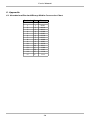
6. Appendix........................................................................................................................33
6.1 Hexadecimal/Decimal/Binary Nibble Conversion Chart...............................................33
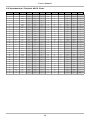
6.1 Hexadecimal / Decimal ASCII Chart..............................................................................34
2
User's Manual
ServoCenter 4.1 Serial Communication Protocol Reference
This document is intended to explain communication protocol and command details of the
ServoCenter4.1 controller board.
1. Protocol Overview
The ServoCenter 4.1 controller receives messages from the controlling system in the form of
sequences of serial communication bytes called packets. Each byte is serial encoded using
8N1 serial encoding (8 data bits, no parity, and 1 stop bit). For ease of use and flexibility of
operation, two methods of encoding commands is provided: binary and text. Binary
encoding is more compact, more efficient, and easier to access programmatically. ASCII
text encoding is more verbose and less efficient yet is easier to read and easier to access via
a traditional terminal interface. Both binary and ASCII text encoding methods share an
identical command structure and support the entire ServoCenter 4.1 command set.
The ServoCenter 4.1 controller buffers the incoming command stream and will only take an
action once the entire packet has been received and the checksum has been verified as
correct. Incomplete packets, packets with inappropriate board IDs, and packets with
incorrect checksums will be ignored. This allows the controlling system to send command
data at leisure without loss of function. The command buffer will, however, be cleared
whenever the ServoCenter controller is either reset or powered off/on.
Most ServoCenter 4.1 commands return no result data. Certain commands, however, are
designed to return status information about the current servo status & positions as well as
other board settings. ServoCenter 4.1 allows multiple boards to be daisy-chained together
and all be able to send and receive messages. The transmit/receive functionality is
controlled by the various jumper settings of jumper block JP1.
Specific details of the ServoCenter 4.1 protocol and its control commands are discussed in
the following pages. Further information pertaining to the connection, configuration, and
programming of the controller board can be found in the ServoCenter “User's Manual” and
on the Yost Engineering, Inc. web page at: http://www.YostEngineering.com/ServoCenter
3
User's Manual
2. Protocol Packet Format
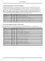
2.1 Binary Packet Format
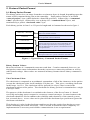
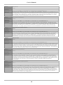
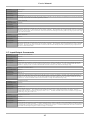
The binary packet size can range from three to nineteen bytes in length, depending upon the
nature of the command being sent to the controller. Each packet consists of an initial
“start of packet” byte (which includes a board ID specifier), followed by a “command
value” specifier byte, followed by zero to thirty-five “command data” bytes, and
terminated by a packet “checksum value” byte.
Each binary packet is from 3 to 35 bytes in length and is formatted as shown in figure 1
240(0xF0) + Board ID
Command
Command Data
...
First Byte – Start of Packet. Calculated by adding
240 to the desired board ID.
Second Byte – Command Value. Selected from one
of the possible control commands.
Command Data / Command Parameters.
Varies from zero to thirty-five bytes depending upon
the command specified in the second byte position.
See the table below for specific command data format
and specification.
Command Data
Checksum Value
Last Byte – Packet Checksum. See the checksum
description below for specific calculation information.
Figure 1 - Typical Binary Command Packet Format
Binary Return Values:
Most ServoCenter 4.1 commands return no result data. Certain commands, however, are
designed to return status information about the current servo status & positions as well as
other board settings. Most values are returned in binary format when a binary command is
issued.
The Checksum Value:
The checksum is computed as an arithmetic summation of all of the characters in the packet
(except the checksum value itself) modulus 239 plus one. This gives a resulting checksum
in the range 1 to 239. The checksum will be ignored if a 0 byte value is sent in the
checksum position of the packet. The checksum for binary packets is transmitted as a single
8-bit byte value.
The purpose of the checksum is to minimize the chances of the ServoCenter 4.1 board
receiving and acting upon corrupted or erroneous control messages. In most instances the
checksum should be used to enhance the reliability and robustness of the control system,
but, as noted above, a zero value can be placed in the checksum byte position to ignore the
checksum calculation.
This placing a 0 value in the checksum position can free the sender from having to worry
about calculating the actual checksum. This is useful in situations where simplicity of
implementation is necessary and reliable communication is not a requirement.
4
User's Manual
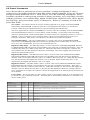
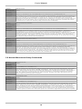
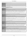
2.2 ASCII Text Packet Format
ASCII text command packets are similar to binary command packets, but are received as a
single formatted line of text. Each text line consists of the following: an ASCII colon
character followed by a list of ASCII encoded integer command values followed by a
terminating newline character. The ASCII encoded command values are all interpreted as
integer values and must be separated by either an ASCII comma character or an ASCII
period character. Thus, legal command characters are: the colon, the comma, the period, the
digits 0 through 9, and the new-line. All other ASCII characters may be included within the
command message string, but are ignored by the controller. For simplicity, the ASCII
encoded commands follow the same format as the binary encoded commands, but ASCII
text encodings of values are used rather than raw binary encodings.
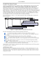
Each ASCII packet is from 3 to 38 comma separated values in length and is formatted as
shown in figure 2.
: BoardId
, Command , Data1 , Data2 , ... , DataN
, Checksum
\n
End of Packet – The
ASCII newline character
Packet Checksum - See the checksum
description below for specific calculation
information.
Command Data / Command Parameters -Varies from
zero to thirty-five comma separated values depending
upon the command specified. See the command table for
specific command data format and specification.
Command Value - Selected from one of the possible control commands.
Board ID Value – ASCII encoded decimal value. Range of 0-15.
Start of ASCII Packet – Indicated by the colon character
Figure 2 - Typical ASCII Command Packet Format
Thus the ASCII packet consists of the the following characters:
: – the ASCII colon character signifies the start of an ASCII text packet.
, – the ASCII comma character acts as a value delimiter when multiple values are
specified.
. – the ASCII period character may also be used as a delimiter.
0~9 – the ASCII digits 0 through 9 are used to create decimal integer values.
\n – the ASCII newline character is used to signify the end of an ASCII command
packet.
\b – the ASCII backspace character can be used to backup through the partially
completed line to correct errors.
Other – all other characters are ignored and may be included to add comments or
other additional information within the command stream.
Additionally, in ASCII mode, command values that are omitted from the ASCII text packet
are assumed to have a value of 0.
ASCII Return Values:
Most ServoCenter 4.1 commands return no result data. Certain commands, however, are
designed to return status information about the current servo status & positions as well as
other board settings. All values are returned in ASCII text format when an ASCII-format
command is issued.
5
User's Manual
The Checksum Value:
The checksum is computed as an arithmetic summation of all of the characters in the packet
(except the checksum value itself) modulus 239 plus one. This gives a resulting checksum
in the range 1 to 239. The checksum will be ignored if a 0 byte value is sent in the
checksum position of the packet. The checksum for ASCII packets is transmitted as an
ASCII encoded decimal value in the range 1 to 239.
The purpose of the checksum is to minimize the chances of the ServoCenter 4.1 board
receiving and acting upon corrupted or erroneous control messages. In most instances the
checksum should be used to enhance the reliability and robustness of the control system,
but, as noted above, a zero value can be placed in the checksum byte position to ignore the
checksum calculation.
This placing a 0 value in the checksum position can free the sender from having to worry
about calculating the actual checksum. This is useful in situations where simplicity of
implementation is necessary and reliable communication is not a requirement.
3. Command Message Format
The ServoCenter 4.1 controller offers 14-bit values to be used to control a servo throughout
its range of motion. This allows the range of motion of a servo to be divided up into 16384
distinct positions (0-16383) thus allowing very precise positioning and smooth transitions.
Since the protocol is based upon 8-bit values, the transmission of 14-bit values is achieved
by sending two values each containing 7-bits of the 14-bit message. For multi-byte value
transmission, the the most-significant portion (MSB) is always sent first and the leastsignificant portion (LSB) is sent second. The MSB is composed of bits 7-13 and the LSB is
composed of bits 0-6.
For example: to send a value of 16,383 (11111111111111 in binary) a value of 127
(1111111 binary) would be sent followed by another value of 127 (1111111 binary). To
send a value of 5,000 (01001110001000 in binary), a value of 39 (0100111 in binary) would
be sent followed by another value of 8 (0001000 in binary).
A similar concept is used to send other multi-value parameters such as percentages and
times. In these instances, the values are divided up into ones-place values and hundredthsplace values that are combined to form one complete decimal number.
For example: to send a percentage value of 50.25% a value of 50 would be transmitted
followed by a value of 25. To send a time of 22.50 seconds the user would transmit a value
of 22 followed by a value of 50.
Some commands encode additional information in use-specific ways. The details of these
encodings are described with the details of each command in the “command details” section
of this document.
6
User's Manual
4. Command Overview
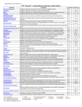
There are over 130 different command messages that are grouped numerically by function.
Unused command message bytes are reserved for future expansion.
When looking at the following command message tables, note the following:
•
•
•
•
•
•
•
Ranges shown are inclusive
Items marked with a % indicate a percentage value.
Items marked with a ∆ indicate a change value.
“Raw” positions are always referenced as a 14-bit value that determines a position between the
globally defined raw “Minimum Pulse Width” and “Maximum Pulse Width” settings.
“Scaled” positions are referenced between a channel's particularly set minimum and maximum
position. This allows a user to set-up min/max 'stops' and the specify subsequent positions as a
simple 14-bit number that is translated into an actual position between the currently set min and max
position. Thus, a value of 0 would move the servo to the minimum position, a value of 16383 would
move the servo to the maximum position, a value of 8191 would move the servo to the position
precisely between the min and max position, etc.
“Percent” positions are also scaled to be between the currently set min/max position for the channel,
but are specified as a percentage. Thus, a value of 0.00% would move the servo to the minimum
position, a value of 100.00% would move the servo to the maximum position, a value of 50.00%
would move the servo to the position precisely between the min and max position, etc. Percentage
values are often encoded as two bytes with the first indicating the ones place of the value, and the
second indicating the hundredths place of the value.
The “Data Len” field indicates the number of additional data-bytes the command expects to follow
the command-byte itself. This number doesn't include the Board ID, Command ID, or Checksum
bytes. Thus, the total message size can be calculated by adding three bytes to the “Data Len” listed in
the table.
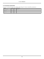
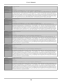
4.1 Normal Movement Servo Commands
Normal movement commands provide a way to precisely position servos using the full 14bit precision of the controller, but have a longer command length than the corresponding
“compact movement commands”.
Description
Command
Data Len Data Descriptions
Quick Move Raw
0 (0x00)
3
SvNum(0~15), SvPosMSB(0~127), SvPosLSB(0~127)
Quick Move Scaled
1 (0x01)
3
SvNum(0~15), SvPosMSB(0~127), SvPosLSB(0~127)
Quick Move Percent
2 (0x02)
3
SvNum(0~15), %SvPosOnes(0~100),%SvPosHundredths(0~99)
Move Raw
3 (0x03)
5
SvNum(0~15),SvPosMSB(0~127),SvPosLSB(0~127),%SvSpeedOnes(0~100),%SvSpeedHundredths(0~99)
Move Raw CW
4 (0x04)
5
SvNum(0~15),∆SvPosMSB(0~127),∆SvPosLSB(0~127),%SvSpeedOnes(0~100),%SvSpeedHundredths(0~99)
Move Raw CCW
5 (0x05)
5
SvNum(0~15),∆SvPosMSB(0~127),∆SvPosLSB(0~127),%SvSpeedOnes(0~100),%SvSpeedHundredths(0~99)
Move Scaled
6 (0x06)
5
SvNum(0~15),SvPosMSB(0~127),SvPosLSB(0~127),%SvSpeedOnes(0~100),%SvSpeedHundredths(0~99)
Move Scaled CW
7 (0x07)
5
SvNum(0~15),∆SvPosMSB(0~127),∆SvPosLSB(0~127),%SvSpeedOnes(0~100),%SvSpeedHundredths(0~99)
Move Scaled CCW
8 (0x08)
5
SvNum(0~15),∆SvPosMSB(0~127),∆SvPosLSB(0~127),%SvSpeedOnes(0~100),%SvSpeedHundredths(0~99)
Move Percent
9 (0x09)
5
SvNum(0~15),%SvPosOnes(0~100),%SvPosHundredths(0~99),%SvSpeedOnes(0~100),%SvSpeedHundredths(0~99)
Move Percent CW
10 (0x0a)
5
SvNum(0~15), ∆%SvPosOnes(0~100), ∆%SvPosHundredths(0~99),%SvSpeedOnes(0~100),%SvSpeedHundredths(0~99)
Move Percent CCW
11 (0x0b)
5
SvNum(0~15), ∆%SvPosOnes(0~100), ∆%SvPosHundredths(0~99),%SvSpeedOnes(0~100),%SvSpeedHundredths(0~99)
Timed Move Raw
12 (0x0c)
5
SvNum(0~15),SvPosMSB(0~127),SvPosLSB(0~127),TimeOnes(0~239),TimeHundredths(0~99)
Timed Move Raw CW
13 (0x0d)
5
SvNum(0~15),∆SvPosMSB(0~127),∆SvPosLSB(0~127),TimeOnes(0~239),TimeHundredths(0~99)
Timed Move Raw CCW
14 (0x0e)
5
SvNum(0~15),∆SvPosMSB(0~127),∆SvPosLSB(0~127),TimeOnes(0~239),TimeHundredths(0~99)
Timed Move Scaled
15 (0x0f)
5
SvNum(0~15),SvPosMSB(0~127),SvPosLSB(0~127),TimeOnes(0~239),TimeHundredths(0~99)
Timed Move Scaled CW
16 (0x10)
5
SvNum(0~15),∆SvPosMSB(0~127),∆SvPosLSB(0~127),TimeOnes(0~239),TimeHundredths(0~99)
Timed Move Scaled CCW
17 (0x11)
5
SvNum(0~15),∆SvPosMSB(0~127),∆SvPosLSB(0~127),TimeOnes(0~239),TimeHundredths(0~99)
Timed Move Percent
18 (0x12)
5
SvNum(0~15),%SvPosOnes(0~100),%SvPosHundredths(0~99),TimeOnes(0~239),TimeHundredths(0~99)
Timed Move Percent CW
19 (0x13)
5
SvNum(0~15), ∆%SvPosOnes(0~100), ∆%SvPosHundredths(0~99),TimeOnes(0~239),TimeHundredths(0~99)
Timed Move Percent CCW
20 (0x14)
5
SvNum(0~15), ∆%SvPosOnes(0~100), ∆%SvPosHundredths(0~99),TimeOnes(0~239),TimeHundredths(0~99)
7
User's Manual
4.2 Normal Movement Group Commands
Normal movement group commands provide a way to precisely position the all 16 servos
simultaneously using the full 14-bit precision of the controller. All 16 servo positions are
encoded as a 32-byte message grouped as 16 two-byte pairs. Servo S0 is sent as the first
pair of bytes, S2 the second pair, etc. Each pair is encoded with the more significant value
first. Values that are outside of the specified range are ignored - this can be useful for
allowing a group movement command to effectively skip servos thus leaving them in their
current position rather than updating them with the rest of the group.
Description
Command Data Len Data Descriptions
Group QuickMove Raw
21 (0x15)
32
16 x [ SvPosMSB(0~127), SvPosLSB(0~127)]
Group QuickMove Scaled
22 (0x16)
32
16 x [ SvPosMSB(0~127), SvPosLSB(0~127)]
Group QuickMove Percent
23 (0x17)
32
16 x [%SvPosOnes(0~100),%SvPosHundredths(0~99)]
Group Move Raw
24 (0x18)
33
16 x [ SvPosMSB(0~127), SvPosLSB(0~127)] , %SvSpeedOnes(0~100)
Group Move Scaled
25 (0x19)
33
16 x [ SvPosMSB(0~127), SvPosLSB(0~127)] , %SvSpeedOnes(0~100)
Group Move Percent
26 (0x1a)
33
16 x [%SvPosOnes(0~100),%SvPosHundredths(0~99)] , %SvSpeedOnes(0~100)
Group Timed Move Raw
27 (0x1b)
33
16 x [ SvPosMSB(0~127), SvPosLSB(0~127)] , SvTimeTenths(0-239)
Group Timed Move Scaled
28 (0x1c)
33
16 x [ SvPosMSB(0~127), SvPosLSB(0~127)] , SvTimeTenths(0-239)
Group Timed Move Percent
29 (0x1d)
33
16 x [%SvPosOnes(0~100),%SvPosHundredths(0~99)] , SvTimeTenths(0-239)
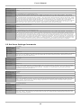
4.3 Compact Movement Servo Commands
Compact movement commands provide a way to roughly position servos using 7-bit
accuracy, but have a shorter command length and thus exhibit lower communication latency.
Description
Command Data Len Data Descriptions
Compact Quick Move Raw
32 (0x20)
2
SvNum(0~15), SvPosMSB(0~127)
Compact Quick Move Scaled
33 (0x21)
2
SvNum(0~15), SvPosMSB(0~127)
Compact Quick Move Percent
34 (0x22)
2
SvNum(0~15), %SvPosOnes(0~100)
Compact Move Raw
35 (0x23)
3
SvNum(0~15),SvPosMSB(0~127),%SvSpeedOnes(0~100)
Compact Move Raw CW
36 (0x24)
3
SvNum(0~15),∆SvPosMSB(0~127),%SvSpeedOnes(0~100)
Compact Move Raw CCW
37 (0x25)
3
SvNum(0~15),∆SvPosMSB(0~127),%SvSpeedOnes(0~100)
Compact Move Scaled
38 (0x26)
3
SvNum(0~15),SvPosMSB(0~127),%SvSpeedOnes(0~100)
Compact Move Scaled CW
39 (0x27)
3
SvNum(0~15),∆SvPosMSB(0~127),%SvSpeedOnes(0~100)
Compact Move Scaled CCW
40 (0x28)
3
SvNum(0~15),∆SvPosMSB(0~127),%SvSpeedOnes(0~100)
Compact Move Percent
41 (0x29)
3
SvNum(0~15),%SvPosOnes(0~100),%SvSpeedOnes(0~100)
Compact Move Percent CW
42 (0x2a)
3
SvNum(0~15), ∆%SvPosOnes(0~100),%SvSpeedOnes(0~100)
Compact Move Percent CCW
43 (0x2b)
3
SvNum(0~15), ∆%SvPosOnes(0~100),%SvSpeedOnes(0~100)
Compact Timed Move Raw
44 (0x2c)
3
SvNum(0~15),SvPosMSB(0~127),TimeTenths(0~239)
Compact Timed Move Raw CW
45 (0x2d)
3
SvNum(0~15),∆SvPosMSB(0~127),TimeTenths(0~239)
Compact Timed Move Raw CCW
14 (0x0e)
3
SvNum(0~15),∆SvPosMSB(0~127),TimeTenths(0~239)
Compact Timed Move Scaled
15 (0x0f)
3
SvNum(0~15),SvPosMSB(0~127),TimeTenths(0~239)
Compact Timed Move Scaled CW
16 (0x10)
3
SvNum(0~15),∆SvPosMSB(0~127),TimeTenths(0~239)
Compact Timed Move Scaled CCW
17 (0x11)
3
SvNum(0~15),∆SvPosMSB(0~127),TimeTenths(0~239)
Compact Timed Move Percent
18 (0x12)
3
SvNum(0~15), ∆%SvPosOnes(0~100),TimeTenths(0~239)
Compact Timed Move Percent CW
19 (0x13)
3
SvNum(0~15), ∆%SvPosOnes(0~100),TimeTenths(0~239)
Compact Timed Move Percent CCW
20 (0x14)
3
SvNum(0~15), ∆%SvPosOnes(0~100),TimeTenths(0~239)
8
User's Manual
4.4 Compact Movement Group Commands
Compact movement group commands provide a way to roughly position all 16 servos
simultaneously. The 16 servo positions are encoded as a 16-byte message with servo S0 as
the first byte, S2 the second, etc. Values that are outside of the specified range are ignored this can be useful for allowing a group movement command to effectively skip servos thus
leaving them in their current position rather than updating them with the rest of the group.
Description
Command Data Len Data Descriptions
Compact Group QuickMove Raw
21 (0x15)
16
16 x [ SvPosMSB(0~127)]
Compact Group QuickMove Scaled
22 (0x16)
16
16 x [ SvPosMSB(0~127)]
Compact Group QuickMove Percent
23 (0x17)
16
16 x [%SvPosOnes(0~100)]
Compact Group Move Raw
24 (0x18)
17
16 x [ SvPosMSB(0~127)] , %SvSpeedOnes(0~100)
Compact Group Move Scaled
25 (0x19)
17
16 x [ SvPosMSB(0~127)] , %SvSpeedOnes(0~100)
Compact Group Move Percent
26 (0x1a)
17
16 x [%SvPosOnes(0~100)] , %SvSpeedOnes(0~100)
Compact Group Timed Move Raw
27 (0x1b)
17
16 x [ SvPosMSB(0~127)] , SvTimeTenths(0-239)
Compact Group Timed Move Scaled
28 (0x1c)
17
16 x [ SvPosMSB(0~127)] , SvTimeTenths(0-239)
Compact Group Timed Move Percent
29 (0x1d)
17
16 x [%SvPosOnes(0~100)] , SvTimeTenths(0-239)
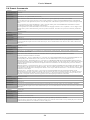
4.5 Set Servo Settings Commands
Set servo setting commands allow the configuration of the parameters associated with servo
control. Each command sets a parameter for one individual servo channel except for the set
pulse width min/max commands which affect all channels.
Description
Command Data Len Data Descriptions
Servo Enable
64 (0x40)
1
SvNum(0~15)
Servo Disable
65 (0x41)
1
SvNum(0~15)
Servo Invert
66 (0x42)
1
SvNum(0~15)
Servo Uninvert
67 (0x43)
1
SvNum(0~15)
Set Servo Disabled State Low
68 (0x44)
1
SvNum(0~15)
Set Servo Disabled State High
69 (0x45)
1
SvNum(0~15)
Set Min
70 (0x46)
3
SvNum(0~15),SvPosMSB(0~127),SvPosLSB(0~127)
Set Max
71 (0x47)
3
SvNum(0~15),SvPosMSB(0~127),SvPosLSB(0~127)
Set Start
72 (0x48)
3
SvNum(0~15),SvPosMSB(0~127),SvPosLSB(0~127)
Set Smoothing Factor
73 (0x49)
2
SvNum(0~15), SmoothFactor(0-127)
Set Max Speed
74 (0x4a)
2
SvNum(0~15), SvMaxSpeed(1~200) in centi-seconds/60 degrees
Set Min to Current
75 (0x4b)
1
SvNum(0~15)
Set Max to Current
76 (0x4c)
1
SvNum(0~15)
Set Start to Current
77 (0x4d)
1
SvNum(0~15)
Set Pulse Width Min
78 (0x4e)
1
PwValue(1~239) in 10 micro-second units
Set Pulse Width Max
79 (0x4f)
1
PwValue(1~239) in 10 micro-second units
4.6 Get Servo Settings Commands
Get servo setting commands allow the reading of parameters associated with servo control.
For the details of the return format, see the detailed command descriptions.
Description
Command Data Len Data Descriptions
Get Servo Enable Status
96 (0x60)
1
SvNum(0~15)
Get Servo Invert Status
97 (0x61)
1
SvNum(0~15)
Get Servo Disabled State
98 (0x62)
1
SvNum(0~15)
Get Current Position Raw
99 (0x63)
1
SvNum(0~15)
Get Current Position Scaled
100 (0x64)
1
SvNum(0~15)
Get Current Position Percent
101 (0x65)
1
SvNum(0~15)
Get Min Position
102 (0x66)
1
SvNum(0~15)
Get Max Position
103 (0x67)
1
SvNum(0~15)
Get Start Position
104 (0x68)
1
SvNum(0~15)
Get Smoothing Factor
105 (0x69)
1
SvNum(0~15)
Get Max Speed
106 (0x6a)
1
SvNum(0~15)
Get Pulse Width Min
107 (0x6b)
0
Get Pulse Width Max
108 (0x6c)
0
9
User's Manual
4.7 Input/Output Commands
Input/Output commands allow interaction with the 16 general purpose I/O channels that are
available on the controller.
Description
Command Data Len Data Descriptions
Read A/D (8 bit resolution)
128 (0x80)
1
ADNum(0~7)
Read A/D (10 bit resolution)
129 (0x81)
1
ADNum(0~7)
Read Digital I/O Pin State
130 (0x82)
1
DIONum(0~15)
Read Digital I/O Pin Direction
131 (0x83)
1
DIONum(0~15)
Read Digital I/O Pin Change Flag
132 (0x84)
1
DIONum(0~15)
Read Digital I/O Pin Start State/Direction
133 (0x85)
1
DIONum(0~15)
Set Digital I/O Pin Low
134 (0x86)
1
DIONum(0~15)
Set Digital I/O Pin High
135 (0x87)
1
DIONum(0~15)
Set Digital I/O Pin as Input
136 (0x88)
1
DIONum(0~15)
Set Digital I/O Pin as Output
137 (0x89)
1
DIONum(0~15)
Set Digital I/O Pin Start State/Direction
138 (0x8a)
2
DIONum(0~15), State/Direction(0~3)
Set All Digital I/O Start States/Directions
139 (0x8b)
0
4.8 Servo Group Mask Commands
Servo group commands allow multiple servos to be controlled with one single command.
The servos that are affected are selected by using a binary servo mask that uses 1 to indicate
a servo that is in the group and a 0 to indicate a servo that isn't in the group. The primary
use of the servo group-mask commands is to allow the reduction of command latency
between servo movements. Since the ServoCenter 4.1 can perform multiple operations
simultaneously by simply sending multiple commands quickly, the use of the more complex
servo group commands should only be used in cases where command communication
latency is critical. For more information about the group commands, see the detailed
command description.
Description
Command Data Len Data Descriptions
Group Mask Quick Move Raw
160 (0xa0)
3~18
GrpMaskMSB(0~255), GrpMaskLSB(0~255), 1~16 x [ SvPosMSB(0~127)]
Group Mask Quick Move Scaled
161 (0xa1)
3~18
GrpMaskMSB(0~255), GrpMaskLSB(0~255), 1~16 x [ SvPosMSB(0~127)]
Group Mask Quick Move Percent
162 (0xa2)
3~18
GrpMaskMSB(0~255), GrpMaskLSB(0~255), 1~16 x [%SvPosOnes(0~100)]
Group Mask Move Raw
163 (0xa3)
3~19
GrpMaskMSB(0~255), GrpMaskLSB(0~255), 1~16 x [ SvPosMSB(0~127)] , %SvSpeedOnes(0~99)
Group Mask Move Scaled
164 (0xa4)
3~19
GrpMaskMSB(0~255), GrpMaskLSB(0~255), 1~16 x [ SvPosMSB(0~127)] , %SvSpeedOnes(0~99)
Group Mask Move Percent
165 (0xa5)
3~19
GrpMaskMSB(0~255), GrpMaskLSB(0~255), 1~16 x [%SvPosOnes(0~100)] , %SvSpeedOnes(0~99)
Group Mask Timed Move Raw
166 (0xa6)
3~19
GrpMaskMSB(0~255), GrpMaskLSB(0~255), 1~16 x [ SvPosMSB(0~127)] , TimeTenths(0~239)
Group Mask Timed Move Scaled
167 (0xa7)
3~19
GrpMaskMSB(0~255), GrpMaskLSB(0~255), 1~16 x [ SvPosMSB(0~127)] , TimeTenths(0~239)
Group Mask Timed Move Percent
168 (0xa8)
3~19
GrpMaskMSB(0~255), GrpMaskLSB(0~255), 1~16 x [%SvPosOnes(0~100)] , TimeTenths(0~239)
10
User's Manual
4.9 Preset Commands
Servo Presets allow a particular set of servo positions / settings and digital I/O states /
settings to be saved and reloaded at a later time with a simple command. There are 64 preset
storage locations numbered 0 to 63. Each “Preset” saves the following information: Servo
Positions (encoded as either percent positions or binary positions), servo skip flags (encoded
with the positions), servo enabled flags, digital I/O directions, digital I/O state values, digital
I/O skip flags, and a preset name (up to 16 characters). Below is a summary of each of the
preset data fields:
Servo Data – Servo data consists of 32 bytes of data organized as 16 groups of SvPositionMSB
followed by SvPositionLSB. Each byte uses the 7 least significant bits (b0-b6) to encode the
position, while the most significant bits have special meanings described below.
The most significant bit of SvPositionMSB(b7) is used to select the encoding of the SvPositionMSB/
SvPositionLSB data as follows: 0=14-bit binary scaled encoding. 1=percentage scaled encoding.
The most significant bit of SvPositionLSB(b7) is used to select servo skipping as follows: 0=servo is
updated. 1=servo is skipped. Servo skipping allows a preset to load while leaving some servo
positions untouched. This allows servo presets to be effectively masked and layered.
Servo Enabled Flags – The servo enabled flags is a 16-bit value sent as SvEnabledFlagsMSB
followed by SvEnabledFlagsLSB with each bit corresponding to the enabled state of a servo. Thus,
b0 is servo S0's enabled state, b1 is servo S1's enabled state, etc.
Digital I/O Skip Flags – The DIO Skip Flags is a 16-bit value sent as DIOSkipFlagsMSB followed
by DIOSkipFlagsLSB with each bit corresponding to the skip state of a digital I/O channel. Thus, b0
is DIO0's skip state, b1 is DIO1's skip state, etc. When the skip state bit is high for a channel, the
state and direction for that digital I/O channel is unmodified. This allows digital I/O presets to be
effectively masked and layered.
Digital I/O Directions – The DIO Directions value is a 16-bit value sent as DIODirectionsMSB
followed by DIODirectionsLSB with each bit corresponding to the pin direction of a digital I/O
channel. Thus, b0 is DIO0's direction value, b1 is DIO1's direction value, etc. When the direction bit
is 0, the direction for that digital I/O channel is set as an input. When the direction bit is 1, the
direction for that digital I/O channel is set as an output.
Digital I/O Values – The DIO Values value is a 16-bit value sent as DIOValuesMSB followed by
DIOValuesLSB with each bit corresponding to the pin state of a digital I/O channel. Thus, b0 is
DIO0's state value, b1 is DIO1's state value, etc. When the state bit is 0, the state for that digital I/O
channel is set low. When the state bit is 1, the state for that digital I/O channel is set high. When a
pin is configured as an input, the value bit controls the application of an internal pull-up resistance for
each channel.
Preset Name – The preset name is a place where a name or description string up to 16 characters can
be stored as a way to identify the preset. This field has no functionality other than as a reminder as to
the use of the preset.
Description
Command
Data Len Data Descriptions
Set Preset Servo Data
192 (0xc0)
33
PresetSlot(0~63) , 16 x [ SvPositionMSB, SvPositionLSB ]
Get Preset Servo Data
193 (0xc1)
1
PresetSlot(0~63)
Set Preset Control Data
194 (0xc2)
9
PresetSlot(0~63) , SvEnabledFlagsMSB , SvEnabledFlagsLSB , DIOSkipFlagsMSB , DIOSkipFlagsLSB ,
DIODirectionsMSB , DIODirectionsLSB , DIOValuesMSB , DIOValuesLSB
Get Preset Control Data
195 (0xc3)
1
PresetSlot(0~63)
Set Preset Name
196 (0xc4)
1~17
Get Preset Name
197 (0xc5)
1
PresetSlot(0~63)
QuickLoad Preset
198 (0xc6)
1
PresetSlot(0~63)
Cross-fade Preset
199 (0xc7)
2
PresetSlot(0~63) , XfadeTimeTenths(0~239)
Store Current as Preset
200 (0xc8)
1
PresetSlot(0~63)
Initialize Preset
201 (0xc9)
1
PresetSlot(0~63)
PresetSlot(0~63) , 1~16 Character Name
11
User's Manual
4.10 General Commands
General commands allow the reading and setting of various controller parameters.
Description
Command Data Len Data Descriptions
Set LED Display Mode
234 (0xea)
1
LedMode(0~7)
Set Watchdog Time
235 (0xeb)
1
WdTimeTenths(1~239)
Commit Settings
236 (0xec)
0
Load Factory Settings
237 (0xed)
0
Reset as Startup
238 (0xee)
0
Display Version
239 (0xef)
0
12
User's Manual
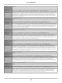
5. Command Details
5.1 Normal Movement Servo Commands
In the tables below you'll find a description of each of the ServoCenter 4.1 commands and a
brief explanation of how and where each command would be used.
Function:
QuickMove Raw
Command Value: 0 (0x00)
Data Bytes:
3
Data Format:
SvNum(0~15), SvPosMSB(0~127), SvPosLSB(0~127)
Description:
The QuickMove Raw command provides a method of instantly moving a single servo (specified by SvNum) to a specified raw position
(specified by SvPosMSB and SvPosLSB). This function is useful when it is desired to move a servo to a position as quickly as possible.
Raw movement modes do not use the set minimum and maximum points to determine the servo's position. With QuickMove no servo
position interpolation is performed and the control signal for the specified servo is immediately modified when the command is issued.
Function:
QuickMove Scaled
Command Value: 1 (0x01)
Data Bytes:
3
Data Format:
SvNum(0~15), SvPosMSB(0~127), SvPosLSB(0~127)
Description:
The QuickMove Scaled command provides a method of instantly moving a single servo (specified by SvNum) to a specified position
(specified by SvPosMSB and SvPosLSB). This function is useful when it is desired to move a servo to a position as quickly as possible.
With Scaled QuickMove no servo position interpolation is performed and the control signal for that specified servo is immediately
modified when the command is issued. Scaled movement modes use the set minimum and maximum points for the given servo channel to
determine the servo's position. The Scaled position value can be thought of as a 14-bit value calculated between the minimum and the
maximum. Thus 0 is the minimum, 16383 is the maximum, 8191 is the midpoint between the set minimum and maximum, etc.
Function:
QuickMove Percent
Command Value: 2 (0x02)
Data Bytes:
3
Data Format:
SvNum(0~15), %SvPosOnes(0~100), %SvPosHundredths(0~99)
Description:
The QuickMove Percent command provides a method of instantly moving a single servo (specified by SvNum) to a specified position
(specified by %SvPosOnes and %SvPosHundredths). This function is useful when it is desired to move a servo to a position as quickly as
possible. With Percent QuickMove no servo position interpolation is performed and the control signal for that specified servo is
immediately modified when the command is issued. Percent movement modes use the set minimum and maximum points for the given
servo channel to determine the servo's position. The position value can be thought of as a percentage of the range from the minimum to
the maximum. Thus 0.00 is the minimum, 100.00 is the maximum, 50.00 is the midpoint between the set minimum and maximum, etc.
Function:
Move Raw
Command Value: 3 (0x03)
Data Bytes:
5
Data Format:
SvNum(0~15), SvPosMSB(0~127), SvPosLSB(0~127), %SvSpeedOnes(0~100), %SvSpeedHundredths(0~99)
Description:
The Move Raw command is used to change a servo's position at a specified speed. The move raw command moves a servo (specified by
SvNum) to a raw position (specified by SvPosMSB and SvPosLSB) at a particular speed (specified by %SvSpeedOnes and
%SvSpeedHundredths). Raw movement modes do not use the set minimum and maximum points to determine the servo's position. The
specified speed is calculated as a percentage of the preset maximum servo speed for the specified servo channel. Thus, a speed of 50.00 is
half as fast as a speed of 100.00, a speed of 1 is 1/100th as fast as a speed of 100, etc.
Function:
Move Raw CW (Clockwise)
Command Value: 4 (0x04)
Data Bytes:
5
Data Format:
SvNum(0~15) , ΔSvPosMSB(0~127) , ΔSvPosLSB(0~127) , %SvSpeedOnes(0~100) , %SvSpeedHundredths(0~99)
Description:
The Move Raw CW command is used to move a servo's position clockwise by a certain amount at a specified speed. The move raw
clockwise command moves a servo (specified by SvNum) clockwise by a certain number of units (specified by ΔSvPosMSB and
ΔSvPosLSB) at a particular speed (specified by %SvSpeedOnes and %SvSpeedHundredths).
Function:
Move Raw CCW (Counter-Clockwise)
Command Value: 5 (0x05)
Data Bytes:
5
Data Format:
SvNum(0~15),ΔSvPosMSB(0~127),ΔSvPosLSB(0~127),%SvSpeedOnes(0~100),%SvSpeedHundredths(0~99)
Description:
The Move Raw CCW command is used to move a servo's position counter-clockwise by a certain amount at a specified speed. The move
raw counter-clockwise command moves a servo (specified by SvNum) clockwise by a certain number of units (specified by ΔSvPosMSB
and ΔSvPosLSB) at a particular speed (specified by %SvSpeedOnes and %SvSpeedHundredths).
13
User's Manual
Function:
Move Scaled
Command Value: 6 (0x06)
Data Bytes:
5
Data Format:
SvNum(0~15), SvPosMSB(0~127), SvPosLSB(0~127), %SvSpeedOnes(0~100), %SvSpeedHundredths(0~99)
Description:
The Move Scaled command is used to move a servo's position at a specified speed. The move scaled command moves a servo (specified
by SvNum) to a 14-bit scaled position (specified by SvPosMSB and SvPosLSB) at a particular speed (specified by %SvSpeedOnes and
%SvSpeedHundredths). Scaled movement modes use the set minimum and maximum points to determine the servo's position. The
scaled position value can be thought of as a 14-bit value between the minimum and the maximum. Thus 0 is the minimum, 16383 is the
maximum, and 8191 is the midpoint between the set minimum and maximum. The specified speed is calculated as a percentage of the
preset maximum servo speed for the specified servo channel. Thus, a speed of 50.00 is half as fast as a speed of 100.00, a speed of 1 is
1/100th as fast as a speed of 100, etc.
Function:
Move Scaled CW (Clockwise)
Command Value: 7 (0x07)
Data Bytes:
5
Data Format:
SvNum(0~15), ΔSvPosMSB(0~127), ΔSvPosLSB(0~127), %SvSpeedOnes(0~100), %SvSpeedHundredths(0~99)
Description:
The Move Scaled CW command is used to move a servo's position clockwise at a specified speed. The move scaled clockwise command
moves a servo (specified by SvNum) clockwise by a certain amount (specified by ΔSvPosMSB and ΔSvPosLSB) at a particular speed
(specified by %SvSpeedOnes and %SvSpeedHundredths). The position indicated by the ΔSvPosMSB and ΔSvPosLSB values can be
thought of as a 14-bit distance based on the range between the minimum position and the maximum position. Thus a distance of 1638
units would move the servo clockwise by a distance of 1/10th of the entire scaled travel range, a distance of 163 units would move the
servo by 1/100th of the entire scaled travel range, etc.
Function:
Move Scaled CCW (Counter-Clockwise)
Command Value: 8 (0x08)
Data Bytes:
5
Data Format:
SvNum(0~15), ΔSvPosMSB(0~127), ΔSvPosLSB(0~127), %SvSpeedOnes(0~100), %SvSpeedHundredths(0~99)
Description:
The Move Scaled CCW command is used to move a servo's position counter-clockwise at a specified speed. The move scaled counterclockwise command moves a servo (specified by SvNum) counter-clockwise by a certain amount (specified by ΔSvPosMSB and
ΔSvPosLSB) at a particular speed (specified by %SvSpeedOnes and %SvSpeedHundredths). The position indicated by the ΔSvPosMSB
and ΔSvPosLSB values can be thought of as a 14-bit distance based on the range between the minimum position and the maximum
position. Thus a distance of 1638 units would move the servo clockwise by a distance of 1/10th of the entire scaled travel range, a distance
of 163 units would move the servo by 1/100th of the entire scaled travel range, etc.
Function:
Move Percent
Command Value: 9 (0x09)
Data Bytes:
5
Data Format:
SvNum(0~15), %SvPosOnes(0~100), %SvPosHundredths(0~99), %SvSpeedOnes(0~100), %SvSpeedHundredths(0~99)
Description:
The Move Percent command is used to move a servo's position at a specified speed. The move percent command moves a servo
(specified by SvNum) to a percentage position (specified by %SvPosOnes and %SvPosHundredths) at a particular speed (specified by
%SvSpeedOnes and %SvSpeedHundredths). Percent movement modes use the set minimum and maximum points to determine the
servo's position. The position value can be thought of as a percentage of the range from the minimum to the maximum. Thus 0.00 is the
minimum, 100.00 is the maximum, and 50.00 is the midpoint between the set minimum and maximum. The specified speed is calculated
as a percentage of the preset maximum servo speed for the specified servo channel. Thus, a speed of 50.00 is half as fast as a speed of
100.00, a speed of 1 is 1/100th as fast as a speed of 100, etc.
Function:
Move Percent CW (Clockwise)
Command Value: 10 (0x0a)
Data Bytes:
5
Data Format:
SvNum(0~15), Δ%SvPosOnes(0~100), Δ%SvPosHundredths(0~99), %SvSpeedOnes(0~100), %SvSpeedHundredths(0~99)
Description:
The Move Percent CW command is used to move a servo's position clockwise at a specified speed. The move percent clockwise
command moves a servo (specified by SvNum) clockwise by a certain percentage (specified by Δ%SvPosOnes and Δ%SvPosHundredths)
at a particular speed (specified by %SvSpeedOnes and %SvSpeedHundredths). The value indicated by the Δ%SvPosOnes and
Δ%SvPosHundredths values is based upon a percentage of the distance between the minimum position and the maximum position. Thus a
distance of 10.00 units would move the servo clockwise by a distance of 1/10th of the entire scaled travel range, a distance of 1.00 unit
would move the servo by 1/100th of the entire min-to-max travel range, etc.
Function:
Move Percent CCW (Counter-Clockwise)
Command Value: 11 (0x0b)
Data Bytes:
5
Data Format:
SvNum(0~15), Δ%SvPosOnes(0~100), Δ%SvPosHundredths(0~99), %SvSpeedOnes(0~100), %SvSpeedHundredths(0~99)
Description:
The Move Percent CCW command is used to move a servo's position counter-clockwise at a specified speed. The move percent counterclockwise command moves a servo (specified by SvNum) counter-clockwise by a certain percentage (specified by Δ%SvPosOnes and Δ
%SvPosHundredths) at a particular speed (specified by %SvSpeedOnes and %SvSpeedHundredths). The value indicated by the
Δ
%SvPosOnes and Δ%SvPosHundredths values is based upon a percentage of the distance between the minimum position and the
maximum position. Thus a distance of 10.00 units would move the servo clockwise by a distance of 1/10th of the entire scaled travel
range, a distance of 1.00 unit would move the servo by 1/100th of the entire min-to-max travel range, etc.
14
User's Manual
Function:
Timed Move Raw
Command Value: 12 (0x0c)
Data Bytes:
5
Data Format:
SvNum(0~15), SvPosMSB(0~127), SvPosLSB(0~127), SvTimeOnes(0~239), SvTimeHundredths(0~99)
Description:
The Timed Move Raw command is used to move a servo's position over the specified time. The timed move raw command moves a servo
(specified by SvNum) to a raw position (specified by SvPosMSB and SvPosLSB) and takes the amount of time (specified by SvTimeOnes
and SvTimeHundredths) to complete the move. Raw movement modes do not use the set minimum and maximum points to determine
the servo's position. The specified time is in seconds and is calculated by adding SvTimeOnes and SvTimeHundredths. For example:
values of SvTimeOnes=5 and SvTimeHundredths=40 would yield a travel time of 5.40 seconds.
Function:
Timed Move Raw CW (Clockwise)
Command Value: 13 (0x0d)
Data Bytes:
5
Data Format:
SvNum(0~15), ΔSvPosMSB(0~127), ΔSvPosLSB(0~127), SvTimeOnes(0~239), SvTimeHundredths(0~99)
Description:
The Timed Move Raw CW command is used to move a servo's position clockwise over the specified time. The timed move raw CW
command moves a servo (specified by SvNum) a number of units (specified by ΔSvPosMSB and ΔSvPosLSB) and takes the amount of
time (specified by SvTimeOnes and SvTimeHundredths) to complete the move. Raw movement modes do not use the set minimum and
maximum points to determine the servo's position. The specified time is in seconds and is calculated by adding SvTimeOnes and
SvTimeHundredths. For example: values of SvTimeOnes=5 and SvTimeHundredths=40 would yield a travel time of 5.40 seconds.
Function:
Timed Move Raw CCW (Counter-Clockwise)
Command Value: 14 (0x0e)
Data Bytes:
5
Data Format:
SvNum(0~15), ΔSvPosMSB(0~127), ΔsvPosLSB(0~127), SvTimeOnes(0~239), SvTimeHundredths(0~99)
Description:
The Timed Move Raw CCW command is used to move a servo's position counter-clockwise over the specified time. This command
moves a servo (specified by SvNum) a number of units (specified by ΔSvPosMSB and ΔSvPosLSB) and takes the amount of time
(specified by SvTimeOnes and SvTimeHundredths) to complete the move. Raw movement modes do not use the set minimum and
maximum points to determine the servo's position. The specified time is in seconds and is calculated by adding SvTimeOnes and
SvTimeHundredths. For example, values of SvTimeOnes=5 and SvTimeHundredths=40 would yield a travel time of 5.40 seconds.
Function:
Timed Move Scaled
Command Value: 15 (0x0f)
Data Bytes:
5
Data Format:
SvNum(0~15), SvPosMSB(0~127), SvPosLSB(0~127), SvTimeOnes(0~239), SvTimeHundredths(0~99)
Description:
The Timed Move Scaled command is used to move a servo's position over the specified time. The timed move scaled command moves a
servo (specified by SvNum) to a scaled 14-bit position (specified by SvPosMSB and SvPosLSB) and takes the amount of time (specified
by SvTimeOnes and SvTimeHundredths) to complete the move. Scaled movement modes use the set minimum and maximum points to
determine the servo's position. The position value can be thought of as a 14-bit number between the minimum and maximum positions.
Thus 0 is the minimum, 16383 is the maximum, and 8191 is the midpoint between the set minimum and maximum. The specified time is
in seconds and is calculated by adding SvTimeOnes and SvTimeHundredths.
Function:
Timed Move Scaled CW (Clockwise)
Command Value: 16 (0x10)
Data Bytes:
5
Data Format:
SvNum(0~15), ΔSvPosMSB(0~127), ΔsvPosLSB(0~127), SvTimeOnes(0~239), SvTimeHundredths(0~99)
Description:
The Timed Move Scaled CW command is used to move a servo's position clockwise over the specified time. This command moves a
servo (specified by SvNum) clockwise by a number of scaled 14-bit units (specified by ΔSvPosMSB and ΔSvPosLSB) and takes the
amount of time (specified by SvTimeOnes and SvTimeHundredths) to complete the move. The value indicated by the ΔSvPosMSB and
ΔSvPosLSB bytes is based upon a scaled distance between the minimum position and the maximum position. Thus a distance of 1638
units would move the servo clockwise by a distance of 1/10th of the min-to-max travel range, a distance of 163 units would move the servo
by 1/100th of the min-to-max travel range, etc. The specified time, in seconds, is calculated by adding SvTimeOnes and
SvTimeHundredths.
Function:
Timed Move Scaled CCW (Counter-Clockwise)
Command Value: 17 (0x11)
Data Bytes:
5
Data Format:
SvNum(0~15), ΔSvPosMSB(0~127), ΔsvPosLSB(0~127), SvTimeOnes(0~239), SvTimeHundredths(0~99)
Description:
The Timed Move Scaled CCW command is used to move a servo's position counter-clockwise over the specified time. The timed move
scaled CCW command moves a servo (specified by SvNum) counter-clockwise by a number of scaled 14-bit units (specified by
ΔSvPosMSB and ΔSvPosLSB) and takes the amount of time (specified by SvTimeOnes and SvTimeHundredths) to complete the move.
The value indicated by the ΔSvPosMSB and ΔSvPosLSB bytes is based upon a scaled distance between the minimum position and the
maximum position. Thus a distance of 1638 units would move the servo clockwise by a distance of 1/10th of the min-to-max travel range,
a distance of 163 units would move the servo by 1/100th of the min-to-max travel range, etc. The specified time is in seconds and is
calculated by adding SvTimeOnes and SvTimeHundredths.
15
User's Manual
Function:
Timed Move Percent
Command Value: 18 (0x12)
Data Bytes:
5
Data Format:
SvNum(0~15), %SvPosOnes(0~100), %SvPosHundredths(0~99), SvTimeOnes(0~239), SvTimeHundredths(0~99)
Description:
The Timed Move Percent command is used to move a servo's position over the specified time. The timed move percent command moves
a servo (specified by SvNum) to a percentage position (specified by %SvPosOnes and %SvPosHundredths) and takes the amount of time
(specified by SvTimeOnes and SvTimeHundredths) to complete the move. Percentage movement modes use the set minimum and
maximum points to determine the servo's position. The position value can be thought of as a percentage of the range from the minimum to
the maximum. Thus 0.00 is the minimum, 100.00 is the maximum, and 50.00 is the midpoint between the set minimum and maximum.
The specified time is in seconds and is calculated by adding SvTimeOnes and SvTimeHundredths.
Function:
Timed Move Percent CW (Clockwise)
Command Value: 19 (0x13)
Data Bytes:
5
Data Format:
SvNum(0~15), Δ%SvPosOnes(0~100), Δ%SvPosHundredths(0~99), SvTimeOnes(0~239), SvTimeHundredths(0~99)
Description:
The Timed Move Percent CW command is used to move a servo's position clockwise over the specified time. The timed move percent
CW command moves a servo (specified by SvNum) clockwise by a number of percentage units (specified by %SvPosOnes and
%SvPosHundredths) and takes the amount of time (specified by SvTimeOnes and SvTimeHundredths) to complete the move. The value
indicated by the Δ%SvPosOnes and Δ%SvPosHundredths bytes is based upon a percentage of the distance between the minimum position
and the maximum position. Thus a distance of 10.00 units would move the servo clockwise by a distance of 1/10th of the min-to-max
travel range, a distance of 1.00 unit would move the servo by 1/100th of the min-to-max travel range, etc. The specified time is in seconds
and is calculated by adding SvTimeOnes and SvTimeHundredths.
Function:
Timed Move Percent CCW (Counter-Clockwise)
Command Value: 20 (0x14)
Data Bytes:
5
Data Format:
SvNum(0~15), Δ%SvPosOnes(0~100), Δ%SvPosHundredths(0~99), SvTimeOnes(0~239), SvTimeHundredths(0~99)
Description:
The Timed Move Percent CCW command is used to move a servo's position counter-clockwise over the specified time. The timed move
percent CCW command moves a servo (specified by SvNum) counter-clockwise by a number of percentage units (specified by
%SvPosOnes and %SvPosHundredths) and takes the amount of time (specified by SvTimeOnes and SvTimeHundredths) to complete the
move. The value indicated by the Δ%SvPosOnes and Δ%SvPosHundredths bytes is based upon a percentage of the distance between the
minimum position and the maximum position. Thus a distance of 10.00 units would move the servo clockwise by a distance of 1/10th of
the min-to-max travel range, a distance of 1.00 unit would move the servo by 1/100th of the min-to-max travel range, etc. The specified
time is in seconds and is calculated by adding SvTimeOnes and SvTimeHundredths.
5.2 Normal Movement Group Commands
Function:
Group QuickMove Raw
Command Value: 21 (0x15)
Data Bytes:
32
Data Format:
16 x [ SvPosMSB(0~127) , SvPosLSB(0~127) ]
Description:
The Group QuickMove Raw command provides a method of instantly positioning all 16 servos with a single command. This command
expects 32 bytes of data to be sent as sixteen SvPosMSB / SvPosLSB pairs. Servo S0 is the first pair received and S15 the last pair
received. Raw movement modes do not use the set minimum and maximum points to determine the servo's position. With QuickMove no
servo position interpolation is performed and the control signal for the specified servo is immediately modified when the command is
issued. Servo positions outside of the specified rage (0~16383) are ignored. This feature can be used to allow specific servos to be
masked or skipped when the group's positions are updated.
Function:
Group QuickMove Scaled
Command Value: 22 (0x16)
Data Bytes:
32
Data Format:
16 x [ SvPosMSB(0~127) , SvPosLSB(0~127) ]
Description:
The Group QuickMove Scaled command provides a method of instantly positioning all 16 servos with a single command. This command
expects 32 bytes of data to be sent as sixteen SvPosMSB / SvPosLSB pairs. Servo S0 is the first pair received and S15 the last pair
received. Scaled movement modes use the set minimum and maximum points to determine the servo's position. The scaled position
values can be thought of as 14-bit values between the minimum and the maximum. Thus 0 is the minimum, 16383 is the maximum, and
8191 is the midpoint between the set minimum and maximum. With QuickMove no servo position interpolation is performed and the
control signal for the specified servo is immediately modified when the command is issued. Servo positions outside of the specified rage
(0~16383) are ignored. This feature can be used to allow specific servos to be masked or skipped when the group's positions are updated.
16
User's Manual
Function:
Group QuickMove Percent
Command Value: 23 (0x17)
Data Bytes:
32
Data Format:
16 x [ %SvPosOnes(0~100) , %SvPosHundredths(0~99) ]
Description:
The Group QuickMove Percent command provides a method of instantly positioning all 16 servos with a single command. This command
expects 32 bytes of data to be sent as sixteen %SvPosOnes / %SvPosHundredths pairs. Servo S0 is the first pair received and S15 the last
pair received. Percent movement modes use the set minimum and maximum points for the given servo channel to determine the servo's
position. The position value can be thought of as a percentage of the range from the minimum to the maximum. Thus 0.00 is the
minimum, 100.00 is the maximum, 50.00 is the midpoint between the set minimum and maximum, etc. With QuickMove no servo
position interpolation is performed and the control signal for the specified servo is immediately modified when the command is issued.
Servo positions outside of the specified rage (0~16383) are ignored. This feature can be used to allow specific servos to be masked or
skipped when the group's positions are updated.
Function:
Group Move Raw
Command Value: 24 (0x18)
Data Bytes:
33
Data Format:
16 x [ SvPosMSB(0~127) , SvPosLSB(0~127) ] , %SvSpeedOnes(1~100)
Description:
The Group Move Raw command provides a method of positioning all 16 servos with a single command. This command expects 32 bytes
of servo data to be sent as sixteen SvPosMSB / SvPosLSB pairs followed by a single byte (%SvSpeedOnes) specifying the movement
speed. Servo S0 is the first pair received and S15 the last pair received. Raw movement modes do not use the set minimum and
maximum points to determine the servo's position. With Move commands, servo position interpolation is performed causing the servos to
move at a percentage of their full speed. Servo positions outside of the specified rage (0~16383) are ignored. This feature can be used to
allow specific servos to be masked or skipped when the group's positions are updated.
Function:
Group Move Scaled
Command Value: 25 (0x19)
Data Bytes:
33
Data Format:
16 x [ SvPosMSB(0~127) , SvPosLSB(0~127) ] , %SvSpeedOnes(1~100)
Description:
The Group Move Scaled command provides a method of positioning all 16 servos with a single command. This command expects 32
bytes of servo data to be sent as sixteen SvPosMSB / SvPosLSB pairs followed by a single byte (%SvSpeedOnes) specifying the
movement speed. Servo S0 is the first pair received and S15 the last pair received. Scaled movement modes use the set minimum and
maximum points to determine the servo's position. The scaled position values can be thought of as 14-bit values between the minimum
and the maximum. Thus 0 is the minimum, 16383 is the maximum, and 8191 is the midpoint between the set minimum and maximum.
With Move commands, servo position interpolation is performed causing the servos to move at a percentage of their full speed. Servo
positions outside of the specified rage (0~16383) are ignored. This feature can be used to allow specific servos to be masked or skipped
when the group's positions are updated.
Function:
Group Move Percent
Command Value: 26 (0x1a)
Data Bytes:
33
Data Format:
16 x [ %SvPosOnes(0~100) , %SvPosHundredths(0~99) ], %SvSpeedOnes(1~100)
Description:
The Group Move Percent command provides a method of positioning all 16 servos with a single command. This command expects 32
bytes of servo data to be sent as sixteen %SvPosOnes / %SvPosHundredths pairs followed by a single byte (%SvSpeedOnes) specifying
the movement speed. Servo S0 is the first pair received and S15 the last pair received. Percent movement modes use the set minimum and
maximum points for the given servo channel to determine the servo's position. The position value can be thought of as a percentage of the
range from the minimum to the maximum. Thus 0.00 is the minimum, 100.00 is the maximum, 50.00 is the midpoint between the set
minimum and maximum, etc. With Move commands, servo position interpolation is performed causing the servos to move at a
percentage of their full speed. Servo positions outside of the specified rage (0~10000) are ignored. This feature can be used to allow
specific servos to be masked or skipped when the group's positions are updated.
Function:
Group Timed Move Raw
Command Value: 27 (0x1b)
Data Bytes:
33
Data Format:
16 x [ SvPosMSB(0~127) , SvPosLSB(0~127) ] , SvTimeTenths(0~239)
Description:
The Group Move Raw command provides a method of positioning all 16 servos with a single command. This command expects 32 bytes
of servo data to be sent as sixteen SvPosMSB / SvPosLSB pairs followed by a single byte (SvTimeTenths) specifying the time in 1/10th
second units that the movement will take to complete. Servo S0 is the first pair received and S15 the last pair received. Raw movement
modes do not use the set minimum and maximum points to determine the servo's position. With Timed commands, servo position
interpolation is performed causing the servos to take the specified amount of time to reach the specified goal position. Servo positions
outside of the specified rage (0~16383) are ignored. This feature can be used to allow specific servos to be masked or skipped when the
group's positions are updated.
17
User's Manual
Function:
Group Timed Move Scaled
Command Value: 28 (0x1c)
Data Bytes:
33
Data Format:
16 x [ SvPosMSB(0~127), SvPosLSB(0~127) ], SvTimeTenths(0~239)
Description:
The Group Move Scaled command provides a method of positioning all 16 servos with a single command. This command expects 32
bytes of servo data to be sent as sixteen SvPosMSB / SvPosLSB pairs followed by a single byte (SvTimeTenths) specifying the time in
1/10th second units that the movement will take to complete. Servo S0 is the first pair received and S15 the last pair received. Scaled
movement modes use the set minimum and maximum points to determine the servo's position. The scaled position values can be thought
of as 14-bit values between the minimum and the maximum. Thus 0 is the minimum, 16383 is the maximum, and 8191 is the midpoint
between the set minimum and maximum. With Timed commands, servo position interpolation is performed causing the servos to take the
specified amount of time to reach the specified goal position. Servo positions outside of the specified rage (0~16383) are ignored. This
feature can be used to allow specific servos to be masked or skipped when the group's positions are updated.
Function:
Group Timed Move Percent
Command Value: 29 (0x1d)
Data Bytes:
33
Data Format:
16 x [ %SvPosOnes(0~100), %SvPosHundredths(0~99) ], SvTimeTenths(0~239)
Description:
The Group Move Percent command provides a method of positioning all 16 servos with a single command. This command expects 32
bytes of servo data to be sent as sixteen %SvPosOnes / %SvPosHundredths pairs followed by a single byte (SvTimeTenths) specifying the
time in 1/10th second units that the movement will take to complete. Servo S0 is the first pair received and S15 the last pair received.
Percent movement modes use the set minimum and maximum points for the given servo channel to determine the servo's position. The
position value can be thought of as a percentage of the range from the minimum to the maximum. Thus 0.00 is the minimum, 100.00 is
the maximum, 50.00 is the midpoint between the set minimum and maximum, etc. With Timed commands, servo position interpolation
is performed causing the servos to take the specified amount of time to reach the specified goal position. Servo positions outside of the
specified rage (0~10000) are ignored. This feature can be used to allow specific servos to be masked or skipped when the group's positions
are updated.
5.3 Compact Movement Servo Commands
Function:
Compact QuickMove Raw
Command Value: 32 (0x20)
Data Bytes:
2
Data Format:
SvNum(0~15), SvPosMSB(0~127)
Description:
The Compact QuickMove command provides a method of instantly moving a single servo (specified by SvNum) to a specified raw
position specified by SvPosMSB. This function is useful when it is desired to move a servo to a position as fast as possible since no servo
position interpolation is performed and the control signal for that specified servo is immediately modified when the command is issued.
Function:
Compact QuickMove Scaled
Command Value: 33 (0x21)
Data Bytes:
2
Data Format:
SvNum(0~15), SvPosMSB(0~127)
Description:
The Compact QuickMove Scaled command provides a method of instantly moving a single servo (specified by SvNum) to a specified
position (specified by SvPosMSB). This function is useful when it is desired to move a servo to a position as quickly as possible. With
Scaled QuickMove no servo position interpolation is performed and the control signal for that specified servo is immediately modified
when the command is issued. Scaled movement modes use the set minimum and maximum points for the given servo channel to
determine the servo's position. The Scaled position value can be thought of as a 7-bit value calculated between the minimum and the
maximum. Thus 0 is the minimum, 127 is the maximum, 63 is the midpoint between the set minimum and maximum, etc.
Function:
Compact QuickMove Percent
Command Value: 34 (0x22)
Data Bytes:
2
Data Format:
SvNum(0~15), %SvPosOnes(0~100)
Description:
The Compact QuickMove Percent command provides a method of instantly moving a single servo (specified by SvNum) to a specified
position (specified by %SvPosOnes). This function is useful when it is desired to move a servo to a position as quickly as possible. With
Percent QuickMove no servo position interpolation is performed and the control signal for that specified servo is immediately modified
when the command is issued. Percent movement modes use the set minimum and maximum points for the given servo channel to
determine the servo's position. The position value can be thought of as a percentage of the range from the minimum to the maximum.
Thus 0 is the minimum, 100 is the maximum, 50 is the midpoint between the set minimum and maximum, etc.
Function:
Compact Move Raw
Command Value: 35 (0x23)
Data Bytes:
3
Data Format:
SvNum(0~15), SvPosMSB(0~127), %SvSpeedOnes(0~100)
Description:
The Compact Move Raw command is used to change a servo's position at a specified speed. The move raw command moves a servo
(specified by SvNum) to a raw position (specified by SvPosMSB) at a particular speed (specified by %SvSpeedOnes). Raw movement
modes do not use the set minimum and maximum points to determine the servo's position. The specified speed is calculated as a
percentage of the preset maximum servo speed for the specified servo channel. Thus, a speed of 50 is half as fast as a speed of 100, a
speed of 1 is 1/100 th as fast as a speed of 100, etc.
18
User's Manual
Function:
Compact Move Raw CW (Clockwise)
Command Value: 36 (0x24)
Data Bytes:
3
Data Format:
SvNum(0~15) , ΔSvPosMSB(0~127) , %SvSpeedOnes(0~100)
Description:
The Compact Move Raw CW command is used to move a servo's position clockwise by a certain amount at a specified speed. This
command moves a servo (specified by SvNum) clockwise by a certain number of units (specified by ΔSvPosMSB) at a particular speed
(specified by %SvSpeedOnes).
Function:
Compact Move Raw CCW (Counter-Clockwise)
Command Value: 37 (0x25)
Data Bytes:
3
Data Format:
SvNum(0~15), ΔSvPosMSB(0~127), %SvSpeedOnes(0~100)
Description:
The Compact Move Raw CCW command is used to move a servo's position counter-clockwise by a certain amount at a specified speed.
This command moves a servo (specified by SvNum) clockwise by a certain number of units (specified by ΔSvPosMSB) at a particular
speed (specified by %SvSpeedOnes).
Function:
Compact Move Scaled
Command Value: 38 (0x26)
Data Bytes:
3
Data Format:
SvNum(0~15), SvPosMSB(0~127), %SvSpeedOnes(0~100)
Description:
The Compact Move Scaled command is used to move a servo's position at a specified speed. The move scaled command moves a servo
(specified by SvNum) to a 7-bit scaled position (specified by SvPosMSB) at a particular speed (specified by %SvSpeedOnes). Scaled
movement modes use the set minimum and maximum points to determine the servo's position. The scaled position value can be thought
of as a 7-bit value between the minimum and the maximum. Thus 0 is the minimum, 127 is the maximum, and 63 is the midpoint
between the set minimum and maximum. The specified speed is calculated as a percentage of the preset maximum servo speed for the
specified servo channel. Thus, a speed of 50 is half as fast as a speed of 100, a speed of 1 is 1/100th as fast as a speed of 100, etc.
Function:
Compact Move Scaled CW (Clockwise)
Command Value: 39 (0x27)
Data Bytes:
3
Data Format:
SvNum(0~15), ΔSvPosMSB(0~127), %SvSpeedOnes(0~100)
Description:
The Compact Move Scaled CW command is used to move a servo's position clockwise at a specified speed. This command moves a
servo (specified by SvNum) clockwise by a certain amount (specified by ΔSvPosMSB) at a particular speed (specified by
%SvSpeedOnes). The position indicated by the ΔSvPosMSB values can be thought of as a 7-bit distance based on the range between the
minimum position and the maximum position. Thus a distance of 32 units would move the servo clockwise by a distance of 1/4th of the
entire scaled travel range, a distance of 1 units would move the servo by 1/128th of the entire scaled travel range, etc.
Function:
Compact Move Scaled CCW (Counter-Clockwise)
Command Value: 40 (0x28)
Data Bytes:
3
Data Format:
SvNum(0~15), ΔSvPosMSB(0~127), %SvSpeedOnes(0~100)
Description:
The Compact Move Scaled CCW command is used to move a servo's position counter-clockwise at a specified speed. The move scaled
counter-clockwise command moves a servo (specified by SvNum) counter-clockwise by a certain amount (specified by ΔSvPosMSB) at a
particular speed (specified by %SvSpeedOnes). The position indicated by the ΔSvPosMSB values can be thought of as a 7-bit distance
based on the range between the minimum position and the maximum position. Thus a distance of 32 units would move the servo
clockwise by a distance of 1/4th of the entire scaled travel range, a distance of 1 units would move the servo by 1/128th of the entire scaled
travel range, etc.
Function:
Compact Move Percent
Command Value: 41 (0x29)
Data Bytes:
3
Data Format:
SvNum(0~15), %SvPosOnes(0~100), %SvSpeedOnes(0~100)
Description:
The Compact Move Percent command is used to move a servo's position at a specified speed. The move percent command moves a servo
(specified by SvNum) to a percentage position (specified by %SvPosOnes) at a particular speed (specified by %SvSpeedOnes). Percent
movement modes use the set minimum and maximum points to determine the servo's position. The position value can be thought of as a
percentage of the range from the minimum to the maximum. Thus 0 is the minimum, 100 is the maximum, and 50 is the midpoint
between the set minimum and maximum. The specified speed is calculated as a percentage of the preset maximum servo speed for the
specified servo channel. Thus, a speed of 50 is half as fast as a speed of 100, a speed of 1 is 1/100th as fast as a speed of 100, etc.
Function:
Compact Move Percent CW (Clockwise)
Command Value: 42 (0x2a)
Data Bytes:
3
Data Format:
SvNum(0~15), Δ%SvPosOnes(0~100), %SvSpeedOnes(0~100)
Description:
The Compact Move Percent CW command is used to move a servo's position clockwise at a specified speed. The move percent clockwise
command moves a servo (specified by SvNum) clockwise by a certain percentage (specified by Δ%SvPosOnes) at a particular speed
(specified by %SvSpeedOnes). The value indicated by the Δ%SvPosOnes value is based upon a percentage of the distance between the
minimum position and the maximum position. Thus a distance of 10 units would move the servo clockwise by a distance of 1/10th of the
max-to-min travel range, a distance of 1 unit would move the servo by 1/100th of the min-to-max travel range, etc.
19
User's Manual
Function:
Compact Move Percent CCW (Counter-Clockwise)
Command Value: 43 (0x2b)
Data Bytes:
3
Data Format:
SvNum(0~15), Δ%SvPosOnes(0~100), %SvSpeedOnes(0~100)
Description:
The Compact Move Percent CCW command is used to move a servo's position counter-clockwise at a specified speed. This command
moves a servo (specified by SvNum) counter-clockwise by a certain percentage (specified by Δ%SvPosOnes) at a particular speed
(specified by %SvSpeedOnes). The value indicated by the Δ%SvPosOnes value is based upon a percentage of the distance between the
minimum position and the maximum position. Thus a distance of 10 units would move the servo clockwise by a distance of 1/10th of the
min-to-max travel range, a distance of 1 unit would move the servo by 1/100th of the min-to-max travel range, etc.
Function:
Compact Timed Move Raw
Command Value: 44 (0x2c)
Data Bytes:
3
Data Format:
SvNum(0~15, SvPosMSB(0~127), SvTimeTenths(0~239)
Description:
The Compact Timed Move Raw command is used to move a servo's position over the specified time. This command moves a servo
(specified by SvNum) to a raw position (specified by SvPosMSB) and takes the amount of time (specified by SvTimeTenths) to complete
the move. Raw movement modes do not use the set minimum and maximum points to determine the servo's position. The specified
movement time is in tenths of a second. For example, a value of SvTimeTenths=25 would yield a travel time of 2.5 seconds.
Function:
Compact Timed Move Raw CW (Clockwise)
Command Value: 45 (0x2d)
Data Bytes:
3
Data Format:
SvNum(0~15), ΔSvPosMSB(0~127), SvTimeTenths(0~239)
Description:
The Compact Timed Move Raw CW command is used to move a servo's position clockwise over the specified time. The timed move raw
CW command moves a servo (specified by SvNum) a number of units (specified by ΔSvPosMSB) and takes the amount of time (specified
by SvTimeTenths) to complete the move. Raw movement modes do not use the set minimum and maximum points to determine the
servo's position. The specified movement time is in tenths of a second. For example, a values of SvTimeTenths=25 would yield a travel
time of 2.5 seconds.
Function:
Compact Timed Move Raw CCW (Counter-Clockwise)
Command Value: 46 (0x2e)
Data Bytes:
3
Data Format:
SvNum(0~15), ΔSvPosMSB(0~127), SvTimeTenths(0~239)
Description:
The Compact Timed Move Raw CCW command is used to move a servo's position counter-clockwise over the specified time. The timed
move raw CCW command moves a servo (specified by SvNum) a number of units (specified by ΔSvPosMSB) and takes the amount of
time (specified by SvTimeTenths) to complete the move. Raw movement modes do not use the set minimum and maximum points to
determine the servo's position. The specified movement time is in tenths of a second. For example, a values of SvTimeTenths=25 would
yield a travel time of 2.5 seconds.
Function:
Compact Timed Move Scaled
Command Value: 47 (0x2f)
Data Bytes:
3
Data Format:
SvNum(0~15), SvPosMSB(0~127), SvTimeTenths(0~239)
Description:
The Compact Timed Move Scaled command is used to move a servo's position over the specified time. The timed move scaled command
moves a servo (specified by SvNum) to a scaled 7-bit position (specified by SvPosMSB) and takes the amount of time (specified by
SvTimeTenths) to complete the move. Scaled movement modes use the set minimum and maximum points to determine the servo's
position. The position value can be thought of as a 7-bit number between the minimum and maximum positions. Thus 0 is the minimum,
127 is the maximum, and 63 is the midpoint between the set minimum and maximum. The specified travel time is in tenths of a second.
Function:
Compact Timed Move Scaled CW (Clockwise)
Command Value: 48 (0x30)
Data Bytes:
3
Data Format:
SvNum(0~15), ΔSvPosMSB(0~127), SvTimeTenths(0~239)
Description:
The Compact Timed Move Scaled CW command is used to move a servo's position clockwise over the specified time. The timed move
scaled CW command moves a servo (specified by SvNum) clockwise by a number of scaled 7-bit units (specified by ΔSvPosMSB) and
takes the amount of time (specified by SvTimeTenths) to complete the move. The value indicated by ΔSvPosMSB is based upon a scaled
distance between the minimum position and the maximum position. Thus a distance of 32 units would move the servo clockwise by a
distance of 1/4th of the min-to-max travel range, a distance of 1 units would move the servo by 1/128th of the min-to-max travel range, etc.
The specified travel time is in tenths of a second.
20
User's Manual
Function:
Compact Timed Move Scaled CCW (Counter-Clockwise)
Command Value: 49 (0x31)
Data Bytes:
3
Data Format:
SvNum(0~15), ΔSvPosMSB(0~127), SvTimeTenths(0~239)
Description:
The Compact Timed Move Scaled CCW command is used to move a servo's position counter-clockwise over the specified time. The
timed move scaled CCW command moves a servo (specified by SvNum) counter-clockwise by a number of scaled 7-bit units (specified by
ΔSvPosMSB) and takes the amount of time (specified by SvTimeTenths) to complete the move. The value indicated by ΔSvPosMSB is
based upon a scaled distance between the minimum position and the maximum position. Thus a distance of 32 units would move the
servo clockwise by a distance of 1/4th of the min-to-max travel range, a distance of 1 units would move the servo by 1/128th of the min-tomax travel range, etc. The specified travel time is in tenths of a second.
Function:
Compact Timed Move Percent
Command Value: 50 (0x32)
Data Bytes:
3
Data Format:
SvNum(0~15), %SvPosOnes(0~100), SvTimeTenths(0~239)
Description:
The Compact Timed Move Percent command is used to move a servo's position over the specified time. The timed move percent
command moves a servo (specified by SvNum) to a percentage position (specified by %SvPosOnes) and takes the amount of time
(specified by SvTimeTenths) to complete the move. Percentage movement modes use the set minimum and maximum points to determine
the servo's position. The position value can be thought of as a percentage of the range from the minimum to the maximum. Thus 0 is the
minimum, 100 is the maximum, and 50 is the midpoint between the set minimum and maximum. The specified travel time is in tenths of
a second.
Function:
Compact Timed Move Percent CW (Clockwise)
Command Value: 51 (0x33)
Data Bytes:
3
Data Format:
SvNum(0~15), Δ%SvPosOnes(0~100), SvTimeTenths(0~239)
Description:
The Compact Timed Move Percent CW command is used to move a servo's position clockwise over the specified time. The compact
timed move percent CW command moves a servo (specified by SvNum) clockwise by a number of percentage units (specified by
%SvPosOnes) and takes the amount of time (specified by SvTimeTenths) to complete the move. The value indicated by Δ%SvPosOnes
is based upon a percentage of the distance between the minimum position and the maximum position. Thus a distance of 10 units would
move the servo clockwise by a distance of 1/10th of the min-to-max travel range, a distance of 1 unit would move the servo by 1/100th of
the min-to-max travel range, etc. The specified travel time is in tenths of a second.
Function:
Compact Timed Move Percent CCW (Counter-Clockwise)
Command Value: 52 (0x34)
Data Bytes:
3
Data Format:
SvNum(0~15), Δ%SvPosOnes(0~100), SvTimeTenths(0~239)
Description:
The Compact Timed Move Percent CCW command is used to move a servo's position counter-clockwise over the specified time. The
compact timed move percent CCW command moves a servo (specified by SvNum) counter-clockwise by a number of percentage units
(specified by %SvPosOnes) and takes the amount of time (specified by SvTimeTenths) to complete the move. The value indicated by Δ
%SvPosOnes is based upon a percentage of the distance between the minimum position and the maximum position. Thus a distance of 10
units would move the servo clockwise by a distance of 1/10th of the min-to-max travel range, a distance of 1 unit would move the servo by
1/100 th of the min-to-max travel range, etc. The specified travel time is in tenths of a second.
5.4 Compact Movement Group Commands
Function:
Compact Group QuickMove Raw
Command Value: 53 (0x35)
Data Bytes:
16
Data Format:
16 x [ SvPosMSB(0~127) ]
Description:
The Compact Group QuickMove Raw command provides a method of instantly positioning all 16 servos with a single command. This
command expects 16 bytes of data to be sent as sixteen SvPosMSB values. Servo S0 is the first value received and S15 the last value
received. Raw movement modes do not use the set minimum and maximum points to determine the servo's position. With QuickMove no
servo position interpolation is performed and the control signal for the specified servo is immediately modified when the command is
issued. Servo positions outside of the specified rage (0~127) are ignored. This feature can be used to allow specific servos to be masked
or skipped when the group's positions are updated.
Function:
Compact Group QuickMove Scaled
Command Value: 54 (0x36)
Data Bytes:
16
Data Format:
16 x [ SvPosMSB(0~127) ]
Description:
The Compact Group QuickMove Scaled command provides a method of instantly positioning all 16 servos with a single command. This
command expects 16 bytes of data to be sent as sixteen SvPosMSB values. Servo S0 is the first value received and S15 the last value
received. Scaled movement modes use the set minimum and maximum points to determine the servo's position. The scaled position
values can be thought of as 7-bit values between the minimum and the maximum. Thus 0 is the minimum, 127 is the maximum, and 63 is
the midpoint between the set minimum and maximum. With QuickMove no servo position interpolation is performed and the control
signal for the specified servo is immediately modified when the command is issued. Servo positions outside of the specified rage (0~127)
are ignored. This feature can be used to allow specific servos to be masked or skipped when the group's positions are updated.
21
User's Manual
Function:
Group QuickMove Percent
Command Value: 55 (0x37)
Data Bytes:
16
Data Format:
16 x [ %SvPosOnes(0~100) ]
Description:
The Compact Group QuickMove Percent command provides a method of instantly positioning all 16 servos with a single command. This
command expects 16 bytes of data to be sent as sixteen %SvPosOnes values. Servo S0 is the first value received and S15 the last value
received. Percent movement modes use the set minimum and maximum points for the given servo channel to determine the servo's
position. The position value can be thought of as a percentage of the range from the minimum to the maximum. Thus 0 is the minimum,
100 is the maximum, 50 is the midpoint between the set minimum and maximum, etc. With QuickMove no servo position interpolation is
performed and the control signal for the specified servo is immediately modified when the command is issued. Servo positions outside of
the specified rage (0~100) are ignored. This feature can be used to allow specific servos to be masked or skipped when the group's
positions are updated.
Function:
Compact Group Move Raw
Command Value: 56 (0x38)
Data Bytes:
17
Data Format:
16 x [ SvPosMSB(0~127) ] , %SvSpeedOnes(1~100)
Description:
The Compact Group Move Raw command provides a method of positioning all 16 servos with a single command. This command expects
16 bytes of servo data to be sent as sixteen SvPosMSB values followed by a single value (%SvSpeedOnes) specifying the movement
speed. Servo S0 is the first value received and S15 the last value received. Raw movement modes do not use the set minimum and
maximum points to determine the servo's position. With Move commands, servo position interpolation is performed causing the servos to
move at a percentage of their full speed. Servo positions outside of the specified rage (0~127) are ignored. This feature can be used to
allow specific servos to be masked or skipped when the group's positions are updated.
Function:
Compact Group Move Scaled
Command Value: 57 (0x39)
Data Bytes:
17
Data Format:
16 x [ SvPosMSB(0~127) ] , %SvSpeedOnes(1~100)
Description:
The Compact Group Move Scaled command provides a method of positioning all 16 servos with a single command. This command
expects 16 bytes of servo data to be sent as sixteen SvPosMSB values followed by a single byte (%SvSpeedOnes) specifying the
movement speed. Servo S0 is the first value recieved and S15 the last value received. Scaled movement modes use the set minimum and
maximum points to determine the servo's position. The scaled position values can be thought of as 7-bit values between the minimum and
the maximum. Thus 0 is the minimum, 127 is the maximum, and 63 is the midpoint between the set minimum and maximum. With Move
commands, servo position interpolation is performed causing the servos to move at a percentage of their full speed. Servo positions
outside of the specified rage (0~127) are ignored. This feature can be used to allow specific servos to be masked or skipped when the
group's positions are updated.
Function:
Compact Group Move Percent
Command Value: 58 (0x3a)
Data Bytes:
17
Data Format:
16 x [ %SvPosOnes(0~100) ] , %SvSpeedOnes(1~100)
Description:
The Compact Group Move Percent command provides a method of positioning all 16 servos with a single command. This command
expects 16 bytes of servo data to be sent as sixteen %SvPosOnes values followed by a single value (%SvSpeedOnes) specifying the
movement speed. Servo S0 is the first value received and S15 the last value received. Percent movement modes use the set minimum and
maximum points for the given servo channel to determine the servo's position. The position value can be thought of as a percentage of the
range from the minimum to the maximum. Thus 0 is the minimum, 100 is the maximum, 50 is the midpoint between the set minimum and
maximum, etc. With Move commands, servo position interpolation is performed causing the servos to move at a percentage of their full
speed. Servo positions outside of the specified rage (0~100) are ignored. This feature can be used to allow specific servos to be masked or
skipped when the group's positions are updated.
Function:
Compact Group Timed Move Raw
Command Value: 59 (0x3b)
Data Bytes:
17
Data Format:
16 x [ SvPosMSB(0~127) ] , SvTimeTenths(0~239)
Description:
The Compact Group Move Raw command provides a method of positioning all 16 servos with a single command. This command expects
16 bytes of servo data to be sent as sixteen SvPosMSB values followed by a single value (SvTimeTenths) specifying the time in 1/10th
second units that the movement will take to complete. Servo S0 is the first value received and S15 the last value received. Raw
movement modes do not use the set minimum and maximum points to determine the servo's position. With Timed commands, servo
position interpolation is performed causing the servos to take the specified amount of time to reach the specified goal position. Servo
positions outside of the specified rage (0~127) are ignored. This feature can be used to allow specific servos to be masked or skipped
when the group's positions are updated.
22
User's Manual
Function:
Compact Group Timed Move Scaled
Command Value: 60 (0x3c)
Data Bytes:
17
Data Format:
16 x [ SvPosMSB(0~127) ], SvTimeTenths(0~239)
Description:
The Compact Group Move Scaled command provides a method of positioning all 16 servos with a single command. This command
expects 16 bytes of servo data to be sent as sixteen SvPosMSB values followed by a single value (SvTimeTenths) specifying the time in
1/10th second units that the movement will take to complete. Servo S0 is the first value received and S15 the last value received. Scaled
movement modes use the set minimum and maximum points to determine the servo's position. The scaled position values can be thought
of as 14-bit values between the minimum and the maximum. Thus 0 is the minimum, 127 is the maximum, and 63 is the midpoint
between the set minimum and maximum. With Timed commands, servo position interpolation is performed causing the servos to take the
specified amount of time to reach the specified goal position. Servo positions outside of the specified rage (0~127) are ignored. This
feature can be used to allow specific servos to be masked or skipped when the group's positions are updated.
Function:
Compact Group Timed Move Percent
Command Value: 61 (0x3d)
Data Bytes:
17
Data Format:
16 x [ %SvPosOnes(0~100) ], SvTimeTenths(0~239)
Description:
The Compact Group Move Percent command provides a method of positioning all 16 servos with a single command. This command
expects 16 bytes of servo data to be sent as sixteen %SvPosOnes values followed by a single value (SvTimeTenths) specifying the time in
1/10th second units that the movement will take to complete. Servo S0 is the first value received and S15 the last value received. Percent
movement modes use the set minimum and maximum points for the given servo channel to determine the servo's position. The position
value can be thought of as a percentage of the range from the minimum to the maximum. Thus 0 is the minimum, 100 is the maximum, 50
is the midpoint between the set minimum and maximum, etc. With Timed commands, servo position interpolation is performed causing
the servos to take the specified amount of time to reach the specified goal position. Servo positions outside of the specified rage (0~100)
are ignored. This feature can be used to allow specific servos to be masked or skipped when the group's positions are updated.
5.5 Set Servo Settings Commands
Function:
Servo Enable
Command Value: 64 (0x40)
Data Bytes:
1
Data Format:
SvNum(0~15)
Description:
The Servo Enable command provides a method of enabling a servo(specified by SvNum). This function is used to enabled a servo channel
that has been previously disabled. With the control signal enabled the servo will actively hold its position. Enabled servos will draw
significantly more power than disabled servos.
Function:
Servo Disable
Command Value: 65 (0x41)
Data Bytes:
1
Data Format:
SvNum(0~15)
Description:
The Servo Disable command provides a method of disabling a servo (specified by SvNum). This function is used to remove the control
signal for a servo channel. With the control signal disabled, the servo will not actively hold its position. This can be useful for disabling a
servo without having to physically disconnect it from the board. A disabled servo can generally be moved by hand and will draw
significantly less power than an enabled servo.
Function:
Servo Invert
Command Value: 66 (0x42)
Data Bytes:
1
Data Format:
SvNum(0~15)
Description:
The Servo Invert command causes the servo channel specified by the first data byte (SvNum) to have its positions seek in an inverted
manner. This means that a raw position value of 0 is the servo's extreme counter-clockwise rotational position and 16383 is the extreme
clockwise position. This function can be useful for dealing with paired servos or with servos that are mounted in such a way that an
inverted positional system is more natural.
Function:
Servo Normal (UnInvert)
Command Value: 67 (0x43)
Data Bytes:
1
Data Format:
SvNum(0~15)
Description:
The Servo Normal command causes the servo channel specified by the first data byte (SvNum) to have its positions seek in the normal,
non-inverted, manner. This means that a raw position value of 0 is the servo's extreme clockwise rotational position and 16383 is the
extreme counter-clockwise position.
23
User's Manual
Function:
Set Servo Disabled State Low
Command Value: 68 (0x44)
Data Bytes:
1
Data Format:
SvNum(0~15)
Description:
The Set Servo Disabled State Low command sets the servo channel specified by the first data byte (SvNum) to have its disabled state set to
low. This means that when the servo channel is disabled the pin will output a low (0 volt) level. This can be useful for using the servo
channels as additional digital outputs by forcing the servo output to a specific digital level.
Function:
Set Servo Disabled State High
Command Value: 69 (0x45)
Data Bytes:
1
Data Format:
SvNum(0~15)
Description:
The Set Servo Disabled State High command sets the servo channel specified by the first data byte (SvNum) to have its disabled state set
to high. This means that when the servo channel is disabled the pin will output a high (0 volt) level. This can be useful for using the
servo channels as additional digital outputs by forcing the servo output to a specific digital level.
Function:
Set Minimum
Command Value: 70 (0x46)
Data Bytes:
3
Data Format:
SvNum(0~15), SvPosMSB(0~127), SvPosLSB(0~127)
Description:
The Set Minimum command sets the minimum raw servo position set-point (specified by SvPosMSB and SvPosLSB) of the specified
servo (specified by SvNum). This minimum position is used in all scaled movement modes of operation. Setting the minimum position
above the start position will cause the start position to be set equal to the minimum. Setting the minimum position above the maximum
will cause the maximum position to be set equal to the minimum.
Function:
Set Maximum
Command Value: 71 (0x47)
Data Bytes:
3
Data Format:
SvNum(0~15), SvPosMSB(0~127), SvPosLSB(0~127)
Description:
The Set Maximum command sets the maximum raw servo position set-point (specified by SvPosMSB and SvPosLSB) of the specified
servo (specified by SvNum). This maximum position is used in all scaled movement modes of operation. Setting the maximum position
below the start position will cause the start position to be set equal to the maximum. Setting the maximum position below the minimum
will cause the minimum position to be set equal to the maximum.
Function:
Set Start
Command Value: 72 (0x48)
Data Bytes:
3
Data Format:
SvNum(0~15), SvPosMSB(0~127), SvPosLSB(0~127)
Description:
The Set Start command sets the starting raw servo position set-point (specified by SvPosMSB and SvPosLSB) of the specified servo
(specified by SvNum). The start position is the position that the servo will assume when the system is powered-up or reset. The start
position is capped and cannot be set greater than the max or less than the min.
Function:
Set Smoothing Factor
Command Value: 73 (0x49)
Data Bytes:
2
Data Format:
SvNum(0~15), SvSmoothFactor(0~127)
Description:
The Set Smoothing Factor command sets the Smoothing Factor for the specified servo (specified by SvNum). The smoothing factor is
applied to the output motion of the servos to produce smoother / less jerky motions. Higher values result in smoother servo motion
outputs, but can introduce a sluggish or delayed response at high levels. A Smoothing Factor of 0 or 1 effectively disables the smoothing
algorithm.
Function:
Set Maximum Speed
Command Value: 74 (0x4a)
Data Bytes:
2
Data Format:
SvNum(0~15), SvMaxSpeed(1~200)
Description:
The Set Maximum Speed command sets the maximum speed (as specified by SvMaxSpeed and measured in centi-seconds per 60° of
travel) that is allowed for a particular servo channel (specified by SvNum). This maximum speed is used to calculate all speed related seek
commands. Different servos have different rated travel speeds depending upon the manufacturer, model, and power supply voltage.
These speeds are generally rated in seconds per 60° of travel so the programmer will have to convert the rated speed (in seconds) to centiseconds by multiplying by 10. The ServoCenter 4.1 controller allows the maximum allowable travel speed to be set independently for each
of the 16 servo channels.
24
User's Manual
Function:
Set Minimum to Current
Command Value: 75 (0x4b)
Data Bytes:
1
Data Format:
SvNum(0~15)
Description:
The Set Minimum to Current command sets the minimum raw servo position set-point to the current raw position of the servo of the
specified servo (specified by SvNum). This minimum position is used in all scaled movement modes of operation. Setting the minimum
position above the start position will cause the start position to be set equal to the minimum. Setting the minimum position above the
maximum will cause the maximum position to be set equal to the minimum.
Function:
Set Maximum to Current
Command Value: 76 (0x4c)
Data Bytes:
1
Data Format:
SvNum(0~15)
Description:
The Set Maximum to Current command sets the maximum raw servo position set-point to the current raw position of the specified servo
(specified by SvNum). This maximum position is used in all scaled movement modes of operation. Setting the maximum position below
the start position will cause the start position to be set equal to the maximum. Setting the maximum position below the minimum will
cause the minimum position to be set equal to the maximum.
Function:
Set Start to Current
Command Value: 77 (0x4d)
Data Bytes:
1
Data Format:
SvNum(0~15)
Description:
The Set Start to Current command sets the startup raw servo position set-point to the current raw position of the specified servo (specified
by SvNum). The start position is the position that the servo will assume when the system is powered-up or reset. The start position is
capped and cannot be set greater than the maximum or less than the minimum.
Function:
Set Pulse Width Min
Command Value: 78 (0x4e)
Data Bytes:
1
Data Format:
PwValue (1-239)
Description:
The Set Pulse Width Minimum command lets the user specify the minimum value of the range of control pulses that are produced by the
ServoCenter 4.1 board for all raw position modes. This minimum value is applied globally to all servo channels of the board. Since some
servos have slightly different control pulse width ranges this value may have to be tweaked to get a full servo motion range out of all raw
position modes. The PwValue is measured in 10 microsecond units thus allowing the board to produce any range of pulses in the range of
10 to 2390 microseconds.
Function:
Set Pulse Width Max
Command Value: 79 (0x4f)
Data Bytes:
1
Data Format:
PwValue (1-239)
Description:
The Set Pulse Width Maximum command lets the user specify the maximum value of the range of control pulses that are produced by the
ServoCenter4.1 board for all raw position modes. This maximum value is applied globally to all servo channels of the board. Since some
servos have slightly different control pulse width ranges this value may have to be tweaked to get a full servo motion range out of all raw
position modes. The PwValue is measured in 10 microsecond units thus allowing the board to produce any range of pulses in the range of
10 to 2390 microseconds.
5.6 Get Servo Settings Commands
Function:
Get Servo Enable Status
Command Value: 96 (0x60)
Data Bytes:
1
Data Format:
SvNum(0~15)
Description:
The Get Servo Enable Status command causes the ServoCenter board to transmit a one byte message corresponding to the enable status of
a particular servo (specified by SvNum). The returned value will be 0 if the servo is disabled and a 1 if the servo is enabled.
Function:
Get Servo Invert Status
Command Value: 97 (0x61)
Data Bytes:
1
Data Format:
SvNum(0~15)
Description:
The Get Servo Invert Status command causes the ServoCenter board to transmit a one byte message corresponding to the invert status of
a particular servo (specified by SvNum). The returned value will be 0 if the servo is non-inverted and a 1 if the servo is inverted.
25
User's Manual
Function:
Get Servo Disabled State
Command Value: 98 (0x62)
Data Bytes:
1
Data Format:
SvNum(0~15)
Description:
The Get Servo Disabled State command causes the ServoCenter board to transmit a one byte message corresponding to the disabled state
of a particular servo (specified by SvNum). The returned value will be 0 if the servo disabled state is low and a 1 if the servo disabled state
is high.
Function:
Get Current Position Raw
Command Value: 99 (0x63)
Data Bytes:
1
Data Format:
SvNum(0~15)
Description:
The Get Current Position Raw command causes the ServoCenter board to transmit a two byte message corresponding to the raw 14-bit
servo position of a particular servo channel (specified by SvNum). The value is returned as two 7-bit values in the SvPosMSB / SvPosLSB
order that combine to form the 14-bit raw position.
Function:
Get Current Position Scaled
Command Value: 100 (0x64)
Data Bytes:
1
Data Format:
SvNum(0~15)
Description:
The Get Current Position Scaled command causes the ServoCenter board to transmit a two byte message corresponding to the scaled 14bit servo position of a particular servo channel (specified by SvNum). The value is returned as two 7-bit values: SvPosMSB followed by
SvPosLSB. These combine to form the 14-bit scaled position.
Function:
Get Current Position Percent
Command Value: 101 (0x65)
Data Bytes:
1
Data Format:
SvNum(0~15)
Description:
The Get Current Position Percent command causes the ServoCenter board to transmit a two byte message corresponding to the servo
percent position (0.00 through 100.00) between the set minimum and maximum positions of a particular servo channel (specified by
SvNum). The value is returned in two bytes: SvPositionOnes followed by SvPositionHundredths.
Function:
Get Min Position
Command Value: 102 (0x66)
Data Bytes:
1
Data Format:
SvNum(0~15)
Description:
The Get Min Position command causes the ServoCenter board to transmit a two byte message corresponding to the currently set minimum
raw position of a particular servo (specified by SvNum).
Function:
Get Max Position
Command Value: 103 (0x67)
Data Bytes:
1
Data Format:
SvNum(0~15)
Description:
The Get Max Position command causes the ServoCenter board to transmit a two byte message corresponding to the currently set
maximum raw position of a particular servo (specified by SvNum).
Function:
Get Start Position
Command Value: 104 (0x68)
Data Bytes:
1
Data Format:
SvNum(0~15)
Description:
The Get Start Position command causes the ServoCenter board to transmit a two byte message corresponding to the currently set starting
raw position of a particular servo (specified by SvNum).
Function:
Get Smooth Factor
Command Value: 105 (0x69)
Data Bytes:
1
Data Format:
SvNum(0~15)
Description:
The Get Smooth Factor command causes the ServoCenter board to transmit a one byte message corresponding to the currently set smooht
factor setting of a particular servo channel (specified by SvNum).
26
User's Manual
Function:
Get Max Speed
Command Value: 106 (0x6a)
Data Bytes:
1
Data Format:
SvNum(0~15)
Description:
The Get Max Speed command causes the ServoCenter board to transmit a one byte message corresponding to the currently set maximum
speed setting of a particular servo channel (specified by SvNum).
Function:
Get Pulse Width Min
Command Value: 107 (0x6b)
Data Bytes:
0
Data Format:
n/a
Description:
The Get Pulse Width Min command causes the ServoCenter 4.1 board to transmit a single value that specifies the minimum control pulse
width that the ServoCenter 4.1 board uses for all raw position commands. This minimum value is applied globally to all servo channels of
the board. The pulse width value is measured in 10 microsecond units thus allowing the board to produce any range of pulses in the range
of 10 to 2390 microseconds.
Function:
Get Pulse Width Max
Command Value: 108 (0x6c)
Data Bytes:
0
Data Format:
n/a
Description:
The Get Pulse Width Max command causes the ServoCenter 4.1 board to transmit a single value that specifies the maximum control pulse
width that the ServoCenter 4.1 board uses for all raw position commands. This maximum value is applied globally to all servo channels
of the board. The pulse width value is measured in 10 microsecond units thus allowing the board to produce any range of pulses in the
range of 10 to 2390 microseconds.
5.7 Input/Output Commands
Function:
Read A/D Pin (8-bit Resolution)
Command Value: 128 (0x80)
Data Bytes:
1
Data Format:
ADNum(0~7)
Description:
The Read A/D (8-bit Resolution) command causes the ServoCenter 4.1 board to transmit a value in the range 0-255 that specifies the
currently read voltage that is present on an analog to digital input pin (specified by ADNum). In binary command mode the result is
returned as a single byte value. In ASCII command mode the result is returned as an ASCII encoded integer string.
Function:
Read A/D Pin (10-bit Resolution)
Command Value: 129 (0x81)
Data Bytes:
1
Data Format:
ADNum(0~7)
Description:
The Read A/D (10-bit Resolution) command causes the ServoCenter 4.1 board to transmit a value in the range 0-1023 that specifies the
currently read voltage that is present on an analog to digital input pin (specified by ADNum). In binary command mode the result is
returned as a two consecutive byte values. The first byte contains the eight most-significant bits; the second byte contains the two leastsignificant bits. In ASCII command mode the result is returned as a single ASCII encoded integer string.
Function:
Read Digital I/O Pin State
Command Value: 130 (0x82)
Data Bytes:
1
Data Format:
DIONum(0~15)
Description:
The Read Digital I/O Pin command causes the ServoCenter4.1 board to transmit a value corresponding to the current state of the digital I/
O pin specified by DIONum. This command works regardless of whether a pin is configured as an input or an output. In binary
command mode the result is returned as a single byte value of 0 or 1. In ASCII command mode the result is returned as a single ASCII
encoded integer string that is either 0 or 1.
Function:
Read Digital I/O Pin Direction
Command Value: 131 (0x83)
Data Bytes:
1
Data Format:
DIONum(0~15)
Description:
The Read Digital I/O Pin Direction command causes the ServoCenter 4.1 board to transmit a value corresponding to the direction state of
the digital I/O pin specified by DIONum. In binary command mode the result is returned as a single byte value where 0 indicates that the
pin is configured as an input and 1 indicates that the pin is configured as an output. In ASCII command mode the result is returned as a
single ASCII encoded integer string that is either 0 for input or 1 for output.
27
User's Manual
Function:
Read Digital I/O Pin Change Flag
Command Value: 132 (0x84)
Data Bytes:
1
Data Format:
DIONum(0~15)
Description:
The Read Digital I/O Pin Change Flag command causes the ServoCenter 4.1 board to transmit a value corresponding to the state of the
internally monitored pin change flag for the pin specified by DIONum. The pin change flag is used to indicate that a pin has changed
state at some point since the change flag was last read. All pins are automatically polled every 2500 microseconds for a change of logic
state. If a state change is detected then the change flag for that pin is set. The change flag for the specified pin is only cleared when it is
read with this command. This command is useful when you want to detect an I/O event (such as a key-press or switch activation) and
want to avoid the complexity and overhead associated with constant polling via the serial interface. In binary command mode the result
is returned as a single byte value where 0 indicates that the pin has not changed and 1 indicates that the pin has changed. In ASCII
command mode the result is returned as a single ASCII encoded integer string that is either 0 or 1.
Function:
Read Digital I/O Pin Start State and Direction
Command Value: 133 (0x85)
Data Bytes:
1
Data Format:
DIONum(0~15)
Description:
The Read Digital I/O Pin Start State and Direction command causes the ServoCenter4.1 board to transmit a value corresponding to the
starting state and direction that is configured for the I/O pin specified by DIONum. Possible return values are defined as: 0=input no
internal pull-up, 1=input with internal pull-up, 2=output low, 3=output high. In binary command mode the result is returned as a single
byte value in the range 0 through 3. In ASCII command mode the result is returned as a single ASCII encoded integer string that is in the
range 0 through 3.
Function:
Set Digital I/O Pin Low
Command Value: 134 (0x86)
Data Bytes:
1
Data Format:
DIONum(0~15)
Description:
The Set Digital I/O Pin Low command's action depends on whether the digital I/O pin (specified by DIONum) is configured as an input or
an output. When the pin is configured as an output, the "Set Digital I/O Pin Low" command sets it to a logic-low state (0 volts). When
the pin is configured as an input, the "Set Digital I/O Pin Low" command deactivates the internal pull-up resistor for the input pin. Initial
pin conditions are determined by the stored start state and direction for the pin.
Function:
Set Digital I/O Pin High
Command Value: 135 (0x87)
Data Bytes:
1
Data Format:
DIONum(0~15)
Description:
The Set Digital I/O Pin High command's action depends on whether the digital I/O pin (specified by DIONum) is configured as an input or
an output. When the pin is configured as an output, the "Set Digital I/O Pin High" command sets it to a logic-high state (5 volts). When
the pin is configured as an input, the "Set Digital I/O Pin High" command activates the internal pull-up resistor for the input pin. Initial pin
conditions are determined by the stored start state and direction for the pin.
Function:
Set Digital I/O Pin as Input
Command Value: 136 (0x88)
Data Bytes:
1
Data Format:
DIONum(0~15)
Description:
The Set Digital I/O Pin as Input command configures the pin (specified by DIONum) as an input. Input pins can have be affected by the
state of the internal pull-up resistor for that input pin. The internal pull-up resistor is activated by using the Set Digital I/O Pin High
function and deactivated by using the Set Digital I/O Pin Low function. Initial pin conditions are determined by the stored start state and
direction for the pin.
Function:
Set Digital I/O Pin as Output
Command Value: 137 (0x89)
Data Bytes:
1
Data Format:
DIONum(0~15)
Description:
The Set Digital I/O Pin as Output command configures the pin (specified by DIONum) as an output. Initial pin conditions are determined
by the stored start state and start direction for the pin.
Function:
Set Digital I/O Pin Start State and Direction
Command Value: 138 (0x8a)
Data Bytes:
2
Data Format:
DIONum(0~15), StateDirectionVal(0~3)
Description:
The Set Digital I/O Pin Start State and Direction command configures the initial pin state and pin direction (specified by for
StateDirectionVal)of the I/O pin specified by DIONum. StateDirectionVal allows for four possible pin configurations: 0=input no internal
pull-up, 1=input with internal pull-up, 2=output low, 3=output high. For the pins settings to be stored through a reset or power cycling,
the settings must be stored using the Commit Settings function.
28
User's Manual
Function:
Set All Digital I/O Pin Start States and Directions
Command Value: 139 (0x8b)
Data Bytes:
0
Data Format:
Description:
The Set All Digital I/O Pin Start States and Directions command configures the initial pin state and pin direction for all pins to the current
settings. To use this command a user would generally set all pin directions and states as desired then call this command to make those the
default settings for the digital I/O pins. For the pins settings to be stored through a reset or power cycling, the settings must be stored
using the Commit Settings function.
5.8 Servo Group Mask Commands
Function:
Group-Mask QuickMove Raw
Command Value: 160 (0xa0)
Data Bytes:
Varies (3~18)
Data Format:
GmaskMSB(0~255),GMaskLSB(0~255), 1~16 bytes of GroupData
Description:
The Group-Mask QuickMove Raw function allows a single command to be applied to multiple servo channels simultaneously. The
GmaskMSB and GmaskLSB values are combined to form a 16-bit groupmask. Each of the 16 bits in the group-mask correspond to an
individual servo channel where bit 0 = servo channel S0, bit 1 = servo channel S1, etc. A value of 1 in a bit position of the group-mask
indicates that the channel will be affected by the command, whereas a value of 0 in a bit position of the group-mask indicates that the
channel will not be affected by the command. The remaining 1-16 GroupData values are used as the data for each of the respective servo
channels that have a 1 bit set in the group-ask. For example: A command issued such that GmaskMSB=0, GmaskLSB=15,
Data=10,20,30,40 would indicate a group-mask of 15 or 0000000000001111 in binary. This indicates that four servos (S0,S1,S2,S3) are
to be moved, the remaining data indicates the positions to which each of the four servos in the group are to be moved. Thus, the four
servos would be moved as follows: S0 to 10, S1 to 20, S2 to 30, S3 to 40. The main advantage of the Group-Mask commands is to reduce
communication latency when moving many servos simultaneously using a single command packet.
Function:
Group-Mask QuickMove Scaled
Command Value: 161 (0xa1)
Data Bytes:
Varies (3~18)
Data Format:
GmaskMSB(0~255),GMaskLSB(0~255), 1~16 bytes of GroupData
Description:
The Group-Mask QuickMove Scaled function allows a single command to be applied to multiple servo channels simultaneously. The
GmaskMSB and GmaskLSB values are combined to form a 16-bit group-mask. Each of the 16 bits in the group-mask correspond to an
individual servo channel where bit 0 = servo channel S0, bit 1 = servo channel S1, etc. A value of 1 in a bit position of the group-mask
indicates that the channel will be affected by the command, whereas a value of 0 in a bit position of the group-mask indicates that the
channel will not be affected by the command. The remaining 1-16 GroupData values are used as the position data for each of the
respective servo channels that have a 1 bit set in the group-ask. Each of the GroupData values has the same meaning as SvPosMSB in the
Compact QuickMove Scaled function and has a valid range of 0~127.
For example: A command issued such that GmaskMSB=0, GmaskLSB=15, Data=10,20,30,40 would indicate a group-mask of 15 or
0000000000001111 in binary. This indicates that four servos (S0,S1,S2,S3) are to be moved, the remaining data indicates the positions
to which each of the four servos in the group are to be moved. Thus, the four servos would be moved as follows: S0 to 10, S1 to 20, S2 to
30, S3 to 40. The main advantage of the Group-Mask commands is to reduce communication latency when moving many servos
simultaneously using a single command packet.
Function:
Group-Mask QuickMove Percent
Command Value: 162 (0xa2)
Data Bytes:
Varies (3~18)
Data Format:
GmaskMSB(0~255),GMaskLSB(0~255), 1~16 bytes of GroupData
Description:
The Group-Mask QuickMove Percent function allows a single command to be applied to multiple servo channels simultaneously. The
GmaskMSB and GmaskLSB values are combined to form a 16-bit group-mask. Each of the 16 bits in the group-mask correspond to an
individual servo channel where bit 0 = servo channel S0, bit 1 = servo channel S1, etc. A value of 1 in a bit position of the group-mask
indicates that the channel will be affected by the command, whereas a value of 0 in a bit position of the group-mask indicates that the
channel will not be affected by the command. The remaining 1-16 GroupData values are used as the position data for each of the
respective servo channels that have a 1 bit set in the group-ask. Each of the GroupData values has the same meaning as %SvPosOnes in
the Compact QuickMove Scaled function and has a valid range of 0~99. See Command 160(0xa0) for a group-mask example.
Function:
Group-Mask Move Raw
Command Value: 163 (0xa3)
Data Bytes:
Varies (4~19)
Data Format:
GmaskMSB(0~255),GMaskLSB(0~255), 1~16 bytes of GroupData, %SvSpeedOnes(1-99)
Description:
The Group-Mask Move Raw function allows a single command to be applied to multiple servo channels simultaneously. The GmaskMSB
and GmaskLSB values are combined to form a 16-bit group-mask. Each of the 16 bits in the group-mask correspond to an individual
servo channel where bit 0 = servo channel S0, bit 1 = servo channel S1, etc. A value of 1 in a bit position of the group-mask indicates that
the channel will be affected by the command, whereas a value of 0 in a bit position of the group-mask indicates that the channel will not be
affected by the command. The next 1-16 GroupData values are used as the position data for each of the respective servo channels that
have a 1 bit set in the group-ask. Each of the GroupData values has the same meaning as SvPosMSB in the Compact Move Raw function
and has a valid range of 0~127. The remaining value has the same meaning as %SvSpeedOnes in the Compact Move Raw function and
is applied to all servos specified in the Group-Mask . See Command 160(0xa0) for a group-mask example.
29
User's Manual
Function:
Group-Mask Move Scaled
Command Value: 164 (0xa4)
Data Bytes:
Varies (4~19)
Data Format:
GmaskMSB(0~255),GMaskLSB(0~255), 1~16 bytes of GroupData, %SvSpeedOnes(1-99)
Description:
The Group-Mask Move Raw function allows a single command to be applied to multiple servo channels simultaneously. The GmaskMSB
and GmaskLSB values are combined to form a 16-bit group-mask. Each of the 16 bits in the group-mask correspond to an individual
servo channel where bit 0 = servo channel S0, bit 1 = servo channel S1, etc. A value of 1 in a bit position of the group-mask indicates
that the channel will be affected by the command, whereas a value of 0 in a bit position of the group-mask indicates that the channel will
not be affected by the command. The next 1-16 GroupData values are used as the position data for each of the respective servo channels
that have a 1 bit set in the group-ask. Each of the GroupData values has the same meaning as SvPosMSB in the Compact Move Scaled
function and has a valid range of 0~127. The remaining value has the same meaning as %SvSpeedOnes in the Compact Move Scaled
function and is applied to all servos specified in the Group-Mask . See Command 160(0xa0) for a group-mask example.
Function:
Group-Mask Move Percent
Command Value: 165 (0xa5)
Data Bytes:
Varies (4~19)
Data Format:
GmaskMSB(0~255),GMaskLSB(0~255), 1~16 bytes of GroupData, %SvSpeedOnes(0-99)
Description:
The Group-Mask Move Percent function allows a single command to be applied to multiple servo channels simultaneously. The
GmaskMSB and GmaskLSB values are combined to form a 16-bit group-mask. Each of the 16 bits in the group-mask correspond to an
individual servo channel where bit 0 = servo channel S0, bit 1 = servo channel S1, etc. A value of 1 in a bit position of the group-mask
indicates that the channel will be affected by the command, whereas a value of 0 in a bit position of the group-mask indicates that the
channel will not be affected by the command. The next 1-16 GroupData values are used as the position data for each of the respective
servo channels that have a 1 bit set in the group-ask. Each of the GroupData values has the same meaning as SvPosMSB in the Compact
Move Percent function and has a valid range of 0~99. The remaining value has the same meaning as %SvSpeedOnes in the Compact
Move Percent function and is applied to all servos specified in the Group-Mask . See Command 160(0xa0) for a group-mask example.
Function:
Group-Mask Timed Move Raw
Command Value: 166 (0xa6)
Data Bytes:
Varies (4~19)
Data Format:
GmaskMSB(0~255),GMaskLSB(0~255), 1~16 bytes of GroupData, SvTimeTenths(0-239)
Description:
The Group-Mask Timed Move Raw function allows a single command to be applied to multiple servo channels simultaneously. The
GmaskMSB and GmaskLSB values are combined to form a 16-bit group-mask. Each of the 16 bits in the group-mask correspond to an
individual servo channel where bit 0 = servo channel S0, bit 1 = servo channel S1, etc. A value of 1 in a bit position of the group-mask
indicates that the channel will be affected by the command, whereas a value of 0 in a bit position of the group-mask indicates that the
channel will not be affected by the command. The next 1-16 GroupData values are used as the position data for each of the respective
servo channels that have a 1 bit set in the group-ask. Each of the GroupData values has the same meaning as SvPosMSB in the Compact
Timed Move Raw function and has a valid range of 0~127. The remaining value, SvTimeTenths is the amount of time that the move
should take as measured in 1/10th second increments. The single SvTimeTenths value is applied to all servos specified in the Group-Mask .
See Command 160(0xa0) for a group-mask example.
Function:
Group-Mask Timed Move Scaled
Command Value: 167 (0xa7)
Data Bytes:
Varies (4~19)
Data Format:
GmaskMSB(0~255),GMaskLSB(0~255), 1~16 bytes of GroupData, SvTimeTenths(0-239)
Description:
The Group-Mask Timed Move Raw function allows a single command to be applied to multiple servo channels simultaneously. The
GmaskMSB and GmaskLSB values are combined to form a 16-bit group-mask. Each of the 16 bits in the group-mask correspond to an
individual servo channel where bit 0 = servo channel S0, bit 1 = servo channel S1, etc. A value of 1 in a bit position of the group-mask
indicates that the channel will be affected by the command, whereas a value of 0 in a bit position of the group-mask indicates that the
channel will not be affected by the command. The next 1-16 GroupData values are used as the position data for each of the respective
servo channels that have a 1 bit set in the group-ask. Each of the GroupData values has the same meaning as SvPosMSB in the Compact
Timed Move Scaled function and has a valid range of 0~127. The remaining value, SvTimeTenths is the amount of time that the move
should take as measured in 1/10th second increments. The single SvTimeTenths value is applied to all servos specified in the Group-Mask .
See Command 160(0xa0) for a group-mask example.
Function:
Group-Mask Timed Move Percent
Command Value: 168 (0xa8)
Data Bytes:
Varies (4~19)
Data Format:
GmaskMSB(0~255),GMaskLSB(0~255), 1~16 bytes of GroupData, SvTimeTenths(0-239)
Description:
The Group-Mask Timed Move Percent function allows a single command to be applied to multiple servo channels simultaneously. The
GmaskMSB and GmaskLSB values are combined to form a 16-bit group-mask. Each of the 16 bits in the group-mask correspond to an
individual servo channel where bit 0 = servo channel S0, bit 1 = servo channel S1, etc. A value of 1 in a bit position of the group-mask
indicates that the channel will be affected by the command, whereas a value of 0 in a bit position of the group-mask indicates that the
channel will not be affected by the command. The next 1-16 GroupData values are used as the position data for each of the respective
servo channels that have a 1 bit set in the group-ask. Each of the GroupData values has the same meaning as SvPosMSB in the Compact
Timed Move Percent function and has a valid range of 0~99. The remaining value, SvTimeTenths is the amount of time that the move
should take as measured in 1/10th second increments. The single SvTimeTenths value is applied to all servos specified in the Group-Mask .
See Command 160(0xa0) for a group-mask example.
30
User's Manual
5.9 Preset Commands
Function:
Set Preset Servo Data
Command Value: 192 (0xc0)
Data Bytes:
33
Data Format:
PresetSlot(0~63) , 16 x [ SvPositionMSB, SvPositionLSB ]
Description:
The Set Preset Servo Data function allows the servo data section of a preset (specified by PresetSlot) to be modified.
The servo data section of a preset consists of 32 bytes of data organized as 16 groups of SvPositionMSB followed by SvPositionLSB.
Each byte uses the 7 least significant bits (b0-b6) to encode the position, while the most significant bits have special meanings described
below.
The most significant bit of SvPositionMSB(b7) is used to select the encoding of the SvPositionMSB/SvPositionLSB data as follows:
0=14-bit binary scaled encoding. 1=percentage scaled encoding.
The most significant bit of SvPositionLSB(b7) is used to select servo skipping as follows: 0=servo is updated. 1=servo is skipped. Servo
skipping allows a preset to load while leaving some servo positions untouched. This allows servo presets to be effectively masked and
layered.
Function:
Get Preset Servo Data
Command Value: 193 (0xc1)
Data Bytes:
1
Data Format:
PresetSlot(0~63)
Description:
The Get Preset Servo Data function causes the board to transmit the 32 byte servo data section of a preset (specified by PresetSlot).
For a more detailed description of the Servo Data Section bytes, see the command details for the Set Preset Servo Data (command 192)
details above.
Function:
Set Preset Control Data
Command Value: 194 (0xc2)
Data Bytes:
9
Data Format:
PresetSlot(0~63), SvEnabledFlagsMSB , SvEnabledFlagsLSB , DIOSkipFlagsMSB , DIOSkipFlagsLSB , DIODirectionsMSB , DIODirectionsLSB ,
DIOValuesMSB , DIOValuesLSB
Description:
The Set Preset Control Data function allows the control data section of a preset (specified by PresetSlot) to be modified.
The Preset Control Data elements are as follows:
Servo Enabled Flags – The servo enabled flags is a 16-bit value sent as SvEnabledFlagsMSB followed by SvEnabledFlagsLSB with each
bit corresponding to the enabled state of a servo. Thus, b0 is servo S0's enabled state, b1 is servo S1's enabled state, etc.
Digital I/O Skip Flags – The DIO Skip Flags is a 16-bit value sent as DIOSkipFlagsMSB followed by DIOSkipFlagsLSB with each bit
corresponding to the skip state of a digital I/O channel. Thus, b0 is DIO0's skip state, b1 is DIO1's skip state, etc. When the skip state bit
is high for a channel, the state and direction for that digital I/O channel is unmodified. This allows digital I/O presets to be effectively
masked and layered.
Digital I/O Directions – The DIO Directions value is a 16-bit value sent as DIODirectionsMSB followed by DIODirectionsLSB with each
bit corresponding to the pin direction of a digital I/O channel. Thus, b0 is DIO0's direction value, b1 is DIO1's direction value, etc. When
the direction bit is 0, the direction for that digital I/O channel is set as an input. When the direction bit is 1, the direction for that digital I/
O channel is set as an output.
Digital I/O Values – The DIO Values value is a 16-bit value sent as DIOValuesMSB followed by DIOValuesLSB with each bit
corresponding to the pin state of a digital I/O channel. Thus, b0 is DIO0's state value, b1 is DIO1's state value, etc. When the state bit is
0, the state for that digital I/O channel is set low. When the state bit is 1, the state for that digital I/O channel is set high. When a pin is
configured as an input, the value bit controls the application of an internal pull-up resistance for each channel.
Function:
Get Preset Control Data
Command Value: 195 (0xc3)
Data Bytes:
1
Data Format:
PresetSlot(0~63)
Description:
The Get Preset Control Data function causes the board to transmit the 8 byte servo data section of a preset (specified by PresetSlot).
For a more detailed description of the Control Data Section bytes, see the command details for the Set Preset Control Data (command 194)
details above.
Function:
Set Preset Name
Command Value: 196 (0xc4)
Data Bytes:
1~17
Data Format:
PresetSlot(0~63), 1-16 Character Name
Description:
The Set Preset Name function allows the name portion of a preset (specified by PresetSlot) to be modified.
The preset name is a place where a name or description string up to 16 characters can be stored as a way to identify the preset. This field
has no functionality other than as a reminder as to the use of the preset.
31
User's Manual
Function:
Get Preset Name
Command Value: 197 (0xc5)
Data Bytes:
1
Data Format:
PresetSlot(0~63)
Description:
The Get Preset Name function causes the board to transmit the name portion of a preset (specified by PresetSlot).
The transmitted name will be 16 characters long.
Function:
Quickload Preset
Command Value: 198 (0xc6)
Data Bytes:
1
Data Format:
PresetSlot(0~63)
Description:
The QuickLoad Preset function causes the preset (specified by PresetSlot) to be loaded. Loading a preset causes the servo positions, servo
enabled states, and digitial I/O directions and states to be modified according to the preset's stored positions and values. If a skip flag
value is set for a servo or digital I/O channel, then that channel's position or value is left unchanged.
Function:
Cross-fade Preset
Command Value: 199 (0xc7)
Data Bytes:
2
Data Format:
PresetSlot(0~63), XfadeTimeTenths(0~239)
Description:
The Croseefade Preset function causes the preset (specified by PresetSlot) to be cross-faded from the current positions over an amount of
time (specified by XfadeTimeTenths). Digital I/O changes are made instantly while servo positions are cross-faded over the time specified.
If a skip flag value is set for a servo or digital I/O channel, then that channel's position or value is left unchanged.
Function:
Store Current as Preset
Command Value: 200 (0xc8)
Data Bytes:
1
Data Format:
PresetSlot(0~63)
Description:
The Store Current as Preset function causes the preset (specified by PresetSlot) to be modified according to the current board
configuration. The board's current servo positions and the digital I/O directions and states are stored. The skip flags are all initialized to
zero. The preset name is left unchanged.
Function:
Initialize Preset
Command Value: 201 (0xc9)
Data Bytes:
1
Data Format:
PresetSlot(0~63)
Description:
The Initialize Preset function causes the preset (specified by PresetSlot) to be initialized to a default setup as follows: servo positions are
set to binary mode and centered with a value of 8191, the digital I/O directions are set as inputs with the internal pull-up voltages
activated, the skip flags are all initialized to zero, and the name is initialized to the PresetSlot number.
5.10 General Commands
Function:
Set LED Mode
Command Value: 234 (0xea)
Data Bytes:
1
Data Format:
LedMode (0~7)
Description:
The Set LED mode command specifies the LED display mode for LED1 and LED2. This can be useful for troubleshooting purposes or
specifying a desired LED output. The default settings is mode 4. Mode values are as follows:
Mode 0: LED2 =off , LED1=off
Mode 1: LED2 =off , LED1=on
Mode 2: LED2 =on , LED1=off
Mode 3: LED2 =on , LED1=on
Mode 4: LED2=statAction , LED1=statRx
Mode 5: LED2=statServoAction , LED1=statRx
Mode 6: LED2=statServoAction , LED1=statAction
Mode 7: reserved
32
User's Manual
Function:
Set Watchdog Time
Command Value: 235 (0xeb)
Data Bytes:
1
Data Format:
WdTimeTenths(0~239)
Description:
The Set Watchdog Time command sets the internal watchdog time to the value specified by WdTimeTenths as measured in 1/10th second
increments. The watchdog feature, when enabled, causes the board to revert to a startup condition if no serial communication has been
received during the specified watchdog time. This is usually used in systems that require a fail-safe condition if communication is
interrupted or the controlling system fails. When the watchdog time is set to a value of 0, the watchdog feature is disabled. For the
watchdog time setting to be stored through a reset or power cycling, the settings must be stored using the Commit Settings function.
Function:
Commit Settings
Command Value: 236 (0xec)
Data Bytes:
0
Data Format:
None.
Description:
The Commit Settings command causes the board to save the current settings into the EEPROM storage. Once the board's settings are
stored in the EEPROM settings of the ServoCenter they will be restored every time the board is either reset or powered up. This allows the
configuration to be saved thus avoiding a configuration process every time the board is reset. Note: the EEPROM storage of the
ServoCenter board has a limited endurance of rewritability (about 100,000 rewrites) so avoid writing a programmatic loop that
continuously commits the settings of the board. The current rewrite count can be viewed by using the “Show Settings” command. A user
can prevent board settings from being written by using jumper JP3 position 1.
Function:
Load Factory Settings
Command Value: 237 (0xed)
Data Bytes:
0
Data Format:
None.
Description:
The Load Factory Settings command causes all of the board's settings to revert to the state that they were in when shipped as new. This
command only loads the settings and doesn't commit the settings to the EEPROM of the board. To restore the settings and save these
settings, the user should perform a “Commit Settings” command following the “Load Factory Settings” command.
Function:
Reset as Startup
Command Value: 238 (0xee)
Data Bytes:
0
Data Format:
None.
Description:
The Reset as Startup command causes the board to perform a software reset of the control software. This command is functionally
equivalent to resetting or cycling the power of the board. All EEPROM settings are loaded and all servo channels are modified according
to these stored settings.
Function:
Display Version
Command Value: 239 (0xef)
Data Bytes:
0
Data Format:
None.
Description:
The Display Version command simply displays the version of the firmware embedded within your ServoCenter board. This can be useful
for allowing software to query the board's version to ensure interoperability between this and other/future YEI products.
33
User's Manual
6. Appendix
6.1 Hexadecimal/Decimal/Binary Nibble Conversion Chart
Decimal
0
1
2
3
4
5
6
7
8
9
10
11
12
13
14
15
Hex
0
1
2
3
4
5
6
7
8
9
A
B
C
D
E
F
Binary
0000
0001
0010
0011
0100
0101
0110
0111
1000
1001
1010
1011
1100
1101
1110
1111
34
User's Manual
6.2 Hexadecimal / Decimal ASCII Chart
ASCII
HEX
Symbol
ASCII
HEX
Symbol
ASCII
HEX
Symbol
ASCII
HEX
Symbol
0
0
NUL
32
20
(space)
64
40
@
96
60
`
1
1
SOH
33
21
!
65
41
A
97
61
a
2
2
STX
34
22
"
66
42
B
98
62
b
3
3
ETX
35
23
#
67
43
C
99
63
c
4
4
EOT
36
24
$
68
44
D
100
64
d
5
5
ENQ
37
25
%
69
45
E
101
65
e
6
6
ACK
38
26
&
70
46
F
102
66
f
7
7
BEL
39
27
'
71
47
G
103
67
g
8
8
BS
40
28
(
72
48
H
104
68
h
9
9
TAB
41
29
)
73
49
I
105
69
i
10
A
LF
42
2A
*
74
4A
J
106
6A
j
11
B
VT
43
2B
+
75
4B
K
107
6B
k
12
C
FF
44
2C
,
76
4C
L
108
6C
l
13
D
CR
45
2D
-
77
4D
M
109
6D
m
14
E
SO
46
2E
.
78
4E
N
110
6E
n
15
F
SI
47
2F
/
79
4F
O
111
6F
o
16
10
DLE
48
30
0
80
50
P
112
70
p
17
11
DC1
49
31
1
81
51
Q
113
71
q
18
12
DC2
50
32
2
82
52
R
114
72
r
19
13
DC3
51
33
3
83
53
S
115
73
s
20
14
DC4
52
34
4
84
54
T
116
74
t
21
15
NAK
53
35
5
85
55
U
117
75
u
22
16
SYN
54
36
6
86
56
V
118
76
v
23
17
ETB
55
37
7
87
57
W
119
77
w
24
18
CAN
56
38
8
88
58
X
120
78
x
25
19
EM
57
39
9
89
59
Y
121
79
y
26
1A
SUB
58
3A
:
90
5A
Z
122
7A
z
27
1B
ESC
59
3B
;
91
5B
[
123
7B
{
28
1C
FS
60
3C
<
92
5C
\
124
7C
|
29
1D
GS
61
3D
=
93
5D
]
125
7D
}
30
1E
RS
62
3E
>
94
5E
^
126
7E
~
31
1F
US
63
3F
?
95
5F
_
127
7F
DEL
35