1
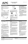
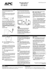
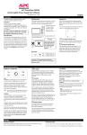
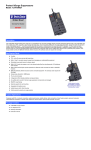
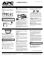
APC Back-UPS Pro®
280/420/650 User’s Manual
990-2037B Revision 3 12/97
Installation and Initial Start-Up
To obtain warranty coverage, please fill out and
return the warranty registration card now.
Check the Site Wiring Fault Indicator
Location: Top right corner of UPS back panel.
Inspection
Inspect the UPS upon receipt. Notify the carrier
and dealer if there is damage. The packaging is
recyclable; save it for reuse or dispose of it
properly.
Caution: If the site wiring fault indicator lights,
get a qualified electrician to correct the building
wiring.
Placement
Connect the Loads
Plug the loads into the output connectors on the
rear of the UPS. To use the UPS as a master
“On/Off” switch, make sure that all of the loads
are switched “On”.
Install the UPS in a protected area that is free of
excessive dust and has adequate air flow. Do
not operate the UPS where the temperature and
humidity is outside the specified limits.
Warning: Changes or modifications to this
unit not expressly approved by the party
responsible for compliance could void the
warranty.
Connect to Utility
Caution: Do not connect a laser
printer to the Battery Backup Outlets.
Cord Straps: Straps are provided to keep cords
from tangling and taking up too much space.
Battery Backup Outlets: These UPS outlets
provide battery power and surge protection to
equipment when utility voltage is outside
acceptable limits. Data sensitive equipment such
as a computer, monitor, or external drive are
connected to these outlets.
Surge Protected Outlets: These outlets are for
equipment that need surge protection but do not
need power during a utility outage (like an inkjet
printer or scanner).
Block Safe Outlets: (420/650): Corded sockets
are provided which accept “block type” plugs
without covering other outlets. Some printers
and external disk drives have block type plugs
that look similar to the one below.
Connect Telephone / Network Surge
Suppression (Optional)
Connect a single line telephone or a 10Base-T/
100Base-Tx network cable into the RJ-45/RJ-11
telephone/network surge protection “IN” jack on
the back of the UPS. Connect from the “OUT”
jack with telephone cable (supplied) or network
cabling (not supplied) to a fax modem or network
port.
Connect Computer Interface
Port (Optional)
PowerChute® plus power management software
is included with this UPS. Connect the supplied
interface cable to the 9-pin computer interface
port on the back panel of the UPS. Connect to
the computer. See software documentation for
installation instructions.
Charge the battery
The UPS charges its battery whenever it
is connected to utility power. The battery will
charge fully during the first 4 hours of normal
operation. Do not expect full runtime during this
initial charge period.
Operating Instructions
Switch “On” — Switch “Off”
With the UPS plugged in, press and
release the On/Off/Test button to supply
power to the loads.
The UPS loads are immediately powered while
the UPS performs a self-test. Press and release
the button again to turn “Off” power to the loads.
It may be convenient to use the UPS as a
master “On/Off” switch for the protected
equipment.
Note: Surge protected outlets are powered
whenever the UPS has utility power.
The on-line LED illuminates when the
UPS is supplying utility power to the
battery backup loads.
Self-test
The UPS performs a self-test automatically when
turned “On”, and every two weeks thereafter (by
default). Automatic self-test eliminates the need
for periodic manual self-tests.
During the self-test, the UPS briefly operates the
loads on-battery. If the UPS passes the self-test,
it returns to on-line operation.
If the UPS fails the self-test it
immediately returns to on-line operation
and lights the replace battery LED.
The loads are not affected by a failed test.
Recharge the battery overnight and perform the
self-test again. If the replace battery LED is still
"On”, replace the battery using the Replacing
the Battery procedure.
On-Battery
During on-battery operation, the onbattery LED illuminates and the UPS
sounds an audible alarm consisting of 4
beeps every 30 seconds. The alarm stops when
the UPS returns to on-line operation.
Low Battery
When the UPS is operating on-battery and the
energy reserve of the battery runs low, the UPS
beeps continuously until the UPS shuts down
from battery exhaustion or returns to on-line
operation.
Overload
When loads exceed the UPS’s capacity,
the overload LED illuminates and the
UPS emits a sustained tone. The alarm
remains “On” until the overload is removed.
Disconnect nonessential load equipment from
the battery backup outlets, to eliminate the
overload.
If the overload is severe, the input circuit breaker
may trip (the resettable center plunger of the
circuit breaker pops out), as well. Disconnect
nonessential load equipment from the UPS to
eliminate the overload and press the plunger
back in to restart the UPS.
If there is AC power and the circuit breaker does
not trip during overload, the loads are still
powered. If the circuit breaker trips or the UPS
attempts to transfer to battery, the loads’ power
will be shut “Off”. Turn the UPS “Off” then back
“On” to repower the loads.
Replace Battery
If the battery fails a self-test, the UPS
emits short beeps for one minute and
the replace battery LED illuminates.
The UPS repeats the alarm every five hours.
Perform the self-test procedure to confirm
replace battery conditions. The alarm stops
when the battery passes the self-test.
Shutdown Mode
If there is no power, the host connected to the
computer interface port can command the UPS
to shut down. This is normally done to preserve
battery capacity after a controlled shutdown of
the protected system. In shutdown mode the
UPS stops supplying power to the load. The online and overload LED indicators flash alternately
or, if the UPS has shutdown due to a low battery,
the UPS will beep once every 4 seconds for
approximately 16 seconds. When line power is
restored, the UPS will return to on-line operation.
Cold Start
Note: Cold start is not a normal operating
condition.
When the UPS is “Off” and there is no utility
power, it is possible to cold start the UPS to
power the loads from the UPS’s battery.
• Press and hold the On/Off/Test button
until the UPS begins beeping.
• Release the On/Off/Test button during the
beeping to start the UPS.
APC, Back-UPS Pro, and PowerChute are registered
trademarks of American Power Conversion.
Storage
Storage conditions
Extended storage
Store the UPS covered and upright in a cool, dry location, with its battery fully
charged. Before storing, charge the UPS for at least 4 hours.
At -15 to +30 °C (+5 to +86 °F), charge the UPS’s battery every 6 months
At +30 to +45 °C (+86 to +113 °F), charge the UPS’s battery every 3 months.
Replacing the Battery
This UPS has an easy to replace hot-swappable battery.
3. Disconnect the two wires connecting the battery to the
UPS. Loosen the wires by wiggling them while pulling
straight back from the battery connector.
Note: Please read the cautions in the APC Safety Guide.
Replacement Batteries
See your dealer or call the number in this manual for information on
replacement battery kits. For 280 and 420 models, order RBC 2. For 650
models, order RBC 4.
4. Connect the new battery in place of the old.
Note: Small sparks at the battery connections are
normal during connection.
Battery Replacement Procedure
Battery replacement is a safe procedure, isolated from electrical hazards.
You may leave the UPS and loads “On” for the following procedure.
5. Place the new battery in the UPS. Use care to avoid
pinching the wires.
Note: Once the battery is disconnected, the loads are not protected
from power outages.
6. Close the battery compartment door and replace the
screws.
1. Lay the UPS on its left side. Remove the two screws
holding on the battery door and open the door.
7. Dispose of the old battery properly at an appropriate
recycling facility or return it to the supplier in the packing
material for the new battery. See the new battery
instructions for more information.
Note: It may be necessary to pull the battery door slightly
toward the front of the unit in order to open the door fully.
2. Gently pull out the battery by grasping the white tab.
Service
If the UPS requires service, please do Not return it to the dealer!
Follow these steps:
1. Use the Troubleshooting section of the Quick Reference Guide to eliminate
common problems.
Troubleshooting
Problem
UPS will not turn “On”.
Possible Cause
On/Off/Test button not
pushed.
UPS input circuit breaker
tripped.
UPS will not turn “On” or
“Off”.
UPS operates on-battery
even though normal line
voltage is thought to
exist.
Computer interface
problem.
UPS's input circuit breaker
tripped.
UPS beeps occasionally.
Normal UPS operation.
UPS does not provide
expected back up time.
The UPS's battery is weak
due to recent outage or is
near the end of its service
life.
On-line and overload
indicators are flashing
alternately.
The UPS was shutdown
®
by PowerChute plus
software.
All indicators are
flashing.
Internal UPS fault.
The UPS operates
normally, but the site
wiring fault indicator is lit.
On-line and on-battery
indicators only are
flashing
Building wiring error such
as missing ground or hot
to neutral wire reversal.
Internal UPS fault.
All indicators are “Off”
and the UPS is not
operating.
The UPS is shutdown and
the battery is discharged
from an extended power
outage.
The replace battery light
is illuminated.
The overload light is
illuminated or flashing
Weak batteries.
Replacement batteries not
connected properly.
The UPS is overloaded.
Solution
Press the On/Off/Test
button to power the UPS
and the loads.
Reduce the load on the
UPS by unplugging
equipment and reset the
circuit breaker by
pressing the plunger
back in.
Disconnect the computer
interface. If the UPS now
works normally, check
the interface cable and
the attached computer.
Reduce the load on the
UPS by unplugging
equipment and reset the
circuit breaker by
pushing the plunger back
in.
None. The UPS is
protecting the load.
Charge the battery. The
UPS's batteries require
recharging after an
extended outage.
Batteries age faster
when put into service
often and when operated
at elevated
temperatures. If the
battery is near the end of
its service life, consider
replacing the battery
even if the replace
battery indicator is not
yet lit.
None. The UPS will
restart automatically
when utility power
returns.
Do not attempt to use
the UPS. Turn the UPS
“Off” and have it serviced
immediately.
Have a qualified
electrician correct the
building wiring.
Do not attempt to use
the UPS. Turn the UPS
“Off” and have it serviced
immediately.
None. The UPS will
return to normal
operation when the
power is restored and
the battery has a
sufficient charge.
Allow the batteries to
recharge for at least 4
hours. If the problem
persists after recharging,
replace the batteries.
Confirm the battery
connections.
Reduce the load on the
UPS by unplugging
equipment.
2. Verify that no circuit breakers are tripped. A tripped circuit breaker is the most
common UPS problem!
3. If the problem persists, call customer service or visit the APC Internet Website
(www.apcc.com).
• Note the model number of the UPS, the serial number, and the date
purchased. A technician will ask you to describe the problem and try to
solve it over the phone, if possible. If this is not possible the technician will
issue a Return Merchandise Authorization Number (RMA#).
• If the UPS is under warranty, repairs are free. If not, there is a repair
charge.
4. Pack the UPS in its original packaging. If the original packing is not available, ask
customer service about obtaining a new set.
• Pack the UPS properly to avoid damage in transit. Never use Styrofoam™
beads for packaging. Damage sustained in transit is not covered under
warranty.
• Include a letter with your name, RMA#, address, copy of the sales receipt,
description of the trouble, your daytime phone number, and a check (if
necessary).
5. Mark the RMA# on the outside of the package .
6. Return the UPS by insured, prepaid carrier to the address given to you by
Customer Service.
APC Contact Information
Internet
USA/Canada …………..
1-800-800-4272
Mexico …………………..
292-0253 / 292-0255
Brazil …………………….
0800-12-72-21
Worldwide ………………
1-401-789-5735
http://www.apcc.com
E-Mail
[email protected]
Specifications
280 VA
Acceptable input voltage
Input voltage (on-line operation)*
Output voltage *
Input Over Current Protection
Frequency limits (on-line operation)
Transfer time
Maximum load
On-battery output voltage
On-battery frequency
On-battery waveshape
Output Over Current Protection
Battery type
Typical battery life
Typical recharge time
Operating temperature
Storage temperature
Operating / storage relative humidity
Operating elevation
Storage elevation
Audible noise at 1 m (3 ft)
Size (H x W x D)
Weight - net (shipping)
For Computer Interface Port Specifications, see the APC Website.
420 VA
650 VA
0 - 160 VAC
81-143 VAC
106-127 VAC
Resettable circuit breaker
47 - 63 Hz (autosensing)
4 ms typical, blackout response time
280 VA
420 VA
650 VA
180 W
260 W
410 W
115 VAC
50 or 60 Hz, ±0.1 Hz; unless synchronized to utility
during brownout
Stepped sine-wave
Overcurrent and short-circuit protected, latching
shutdown on overload
Spill proof, maintenance free, sealed lead-acid
3 to 6 years, depending on number of discharge
cycles and ambient temperature
2 to 5 hours from total discharge
0 to +40 °C (+32 to +104 °F)
-15 to +45 °C (+5 to +113 °F)
0 to 95%, non-condensing
0 to +3,000 m (0 to +10,000 ft)
0 to +15,000 m (0 to +50,000 ft)
<45 dBA
15 x 8.6 x 33.8 cm
16.8 x 11.9 x 36.8 cm
(5.9 x 3.4 x 13.3 in.)
(6.6 x 4.7 x 14.5 in.)
7.5 (9.3) kg
16.6 (20.4) lb.
10.0 (10.9) kg
22.0 (24.0) lb.
12.3 (13.2) kg
27.0 (29.0) lb.
Listing, Certifications and Unlisted
UL 1778, UL 497A, CSA 107.1, FCC part 15
Components
EMI certification
FCC/DOC Class B certified
Electromagnetic immunity
IEC 801-4 level IV, 801-5 level III
* User-adjustable through PowerChute® plus (see software documentation)
Mouser Electronics
Authorized Distributor
Click to View Pricing, Inventory, Delivery & Lifecycle Information:
APC:
BP280S