1
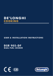
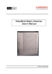
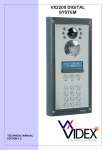
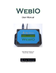
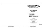
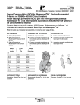
UIM-138 USER INTERFACE
MODULE FOR THE
VX2200 SYSTEM
(FOR USE WITH 138N)
TECHNICAL MANUAL EDITION 1.0
CONTENTS
Manual Introduction
Product Overview
• Key features
UIM-138 Module Layout
Terminal Connections
Technical Specification
Auxiliary Operating Modes
• Auxiliary Input Modes
• Auxiliary Output Modes
Software Installation and Setup
• Launching the Software
• The Main Programmer Screen
• Settings
• Apartments
• Programmer Screen Top Menu
• File
• System
• Download
• Upload
• Sort
• Language
• Communication
• Baud
• About
• Programmer Screen Status and Progress Bar
• Not Detected
• Detected
• Opened File
• Saved File
• Downloading Settings
• Uploading Settings
Installation
• Powering Up the UIM-138 Display Module
Resetting the UIM-138 Display
Quick Software Setup Guide
Connection Diagram
Trouble Shooting
Software Updates / Firmware Updates
Page 2
PAGE
3
3
3-4
4
4
5
5
5
5
5 - 15
6
6
7-9
9 - 10
10 - 15
10 -11
12
12
12 - 13
13
13
14
14
14
14 - 15
14
15
15
15
15
15
15 - 16
16
16
17
17
18
19
TECHNICAL MANUAL EDITION 1.0
MANUAL INTRODUCTION
T
he information in this manual is intended as an installation and setup guide for the UIM-138 display
and voice annunciation module. This manual should be read carefully before the installation
commences. Any damage caused to the equipment due to faulty installations where the information in
this manual has not been followed is not the responsibility of Videx Security Ltd.
V
IDEX run free training courses for engineers who have not installed this system
before. Technical help is also available on 0191 224 3174 during office hours or via
e-mail [email protected]. An electronic copy of this user manual is available for
download by scanning the QR code to the right.
PRODUCT OVERVIEW
T
he UIM-138 display module is designed to interface with the 138N speaker module for the VX2200
system bringing features normally only found on digital door panels to the traditional call button
panels. It will add features to aid users with disabilities and make the process of calling an apartment
more user friendly helping comply with the Equality Act 2010.
The module can be added to any vandal resistant or VR4K door panel for the VX2200 system. The 2
line 16 character blue back lit LCD is protected behind a 6mm Lexan window and displays call progress
information while also producing spoken call progress messages through the speaker of the door panel.
It can be programmed using the current VX2X00 programming software (version 7.0.0.7 or later)
allowing user names, apartment numbers and additional displayed messages to be programmed into
non-volatile memory. The module connects to the 138N speaker module via a ‘plug-in’ wire harness and
connects to a PC or laptop via a standard USB connection.
Three of the auxiliary inputs can be connected to buttons creating a scroll facility with scroll forward,
scroll back and call buttons. With just a speaker unit, the UIM-138 module and the 3 buttons it is possible
to call up to 180 apartments by scrolling to the name and then pressing call. This feature can be used for
both residential, displaying the names of the occupants and commercial, displaying the names of the
companies, departments or offices.
Key features
• 2 line 16 character blue back lit display.
• Voice annunciation output.
• 5 programmable auxiliary inputs which can be programmed as:• Programmable auxiliary messages to display on the LCD.
• Scroll and call buttons to scroll through the user memory and make a call.
• Additional call buttons.
• Door relay activation.
• Concierge call button.
• Activate the auxiliary output.
• End a call.
TECHNICAL MANUAL EDITION 1.0
Page 3
• A switched 0V auxiliary output programmable as:• Triggered by auxiliary input.
• Activate for the duration of a call.
• Activate for a programmed time at the beginning of a call.
• USB port.
• Adjustable display contrast and voice annunciation volume.
UIM-138 MODULE LAYOUT
1.Contrast and speech annunciation volume
controls.
1
2.138N ‘plug-in’ harness connection.
3.USB port.
2
3
4.7 way terminal connections (see description
below).
4
TERMINAL CONNECTIONS
Connection
0V
AO
I1
I2
I3
I4
I5
Page 4
Description
0V input.
Programmable auxiliary output (please refer to
page 5 for list of programming modes).
5 programmable auxiliary inputs,
switched 0V trigger
(please refer to page 5 for list of
programming modes for each input).
TECHNICAL MANUAL EDITION 1.0
TECHNICAL SPECIFICATION
Input Voltage
12V - 14Vdc
Current (standby)
29mA
Current (during operation)
34mA (max.)
Harness connection
5 way pin connector
USB port
USB
Module dimensions
80mm (L) x 60mm (W) x 32mm (D)
AUXILIARY OPERATING MODES
Auxiliary Input Modes
Mode
I1 (Aux 1)
I2 (Aux 2)
I3 (Aux 3)
I4 (Aux 4)
I5 (Aux 5)
1
Auxiliary 1
message
Auxiliary 2
message
Auxiliary 3
message
Auxiliary 4
message
Auxiliary 5
message
2
Call ID.1
Activate AO
currently unavailable
End call
Activate relay
3
Scroll < (up)
Call
Scroll > (down)
currently unavailable
End call
4
Call ID.25
Call ID.26
Call ID.27
Call ID.28
Call ID.29
5 - 10
(Currently unavailable, left for future expansion)
Auxiliary Output Modes
Mode
1
Auxiliary output triggered by auxiliary input I2
2
Auxiliary output triggered for duration of call
3
Auxiliary output triggered for auxiliary output time at beginning of call
4 - 10
B
AO
(Currently unavailable, left for future expansion)
SOFTWARE INSTALLATION AND SETUP
efore connecting the UIM-138 module to a PC or laptop please ensure that the module is connected
to the 138N speaker amp using the ‘plug-in’ wire harness and any necessary auxiliary inputs/outputs
are connected (this will depend on the users requirements). Ensure that the latest VX2X00 version of
software is installed on the PC or laptop (version 7.0.0.7 or later, refer to the quick software setup guide
on page 19) and there is 12Vdc power connected into the 138N speaker amp. After the software is
installed connect the UIM-138 display module to the PC or laptop using a USB cable as shown below
(also refer to the connection diagram on page 20).
Laptop
UIM-138 Display Panel
USB cable
TECHNICAL MANUAL EDITION 1.0
Page 5
Launching the Software
Launch the 2X00PC software by double clicking on the desktop icon.
The initial launch window will appear (as
shown to the right). At the top of the window
the software will show that it is checking for
any devices connected to the PC or laptop.
After a brief period the main programmer screen will appear.
The Main Programmer Screen
If a device has been detected this will be shown at the bottom of the main programmer screen with a
green square (see below). On this screen several programming options can be selected.
The main programmer screen shows several menu options at the top (although several menu options
are shown at the top not all options will be applicable when using the UIM-138 display module) and
two selectable windows on the main screen; ‘settings’ and ‘apartments’. The default tab selected is the
‘settings’ tab and the main display logo field will already have ‘ENTER FLAT’ inserted into the field and
the speech playback field will already have ‘combined’ selected from the drop down menu (seen at the
top of the settings window).
Page 6
TECHNICAL MANUAL EDITION 1.0
Settings
Each heading on the left handside of the ‘settings’ window
consists of two editable field lines with up to 16 characters
each. To the right of each field line there is a ‘centre alignment’
button (as shown on the right) which allows the text entered
into the field line to be centred when shown on the UIM-138
display.
Under the ‘settings’ tab the following fields can be edited:
• Main Display Logo - the main logo text can be entered into each field line. (The information entered
into these fields will be the main logo shown on the UIM-138 display).
• Switch Display Logo - the switch logo text can be entered into each field line. (The information
entered into these fields will be logo that the UIM-138 display switches to after approximately 5
seconds).
• Aux. 1, Aux. 2, Aux. 3, Aux. 4 and Aux 5 display text - additional text can be entered into each
auxiliary field line. (The information entered into these fields will be shown on the UIM-138 display
after the respective auxiliary input I1, I2, I3, I4 or I5 has been triggered).
• Aux. Out Time - the auxiliary output time can be set (in seconds) in this field.
On the right handside of the ‘settings’ tab there are 7 selectable options each with a drop down menu
where the following can be set:
• Speech Playback - the default setting in this field is set to ‘combined’. By clicking on the drop down
menu button (q) on the right of the field this setting can be changed. The three options available
are: none, individual and combined (if ‘none’ is selected then there will be no speech playback when
a call is made to the flat. If ‘individual’ is selected then the speech annunciation will playback the
individual numbers that make up the flat number e.g. if calling flat 25 the speech will playback
“calling two five”. If ‘combined’ is selected then the speech annunciation will playback the combined
flat number e.g. if calling flat number 15 the speech will playback “calling fifteen”).
• Aux.1 Mode - by clicking on the drop down menu button (q) on the right of the field the required
auxiliary mode can be set (a table of auxiliary input modes can be found on page 5). The following
modes can be set and will be active when auxiliary input I1 is triggered:
1. Aux.1 Message - when set into mode 1 the text entered into the ‘Aux.1 display text’
fields will be shown on the UIM-138 display.
2. Call ID.1 - when set into mode 2 then the UIM-138 will trigger the 138N speaker
amp to call phone ID.1 (particularly useful if a 2210A or 2210V concierge unit is
being used).
3. Scroll < (up) - when set into mode 3 then the UIM-138 display will scroll up through
the list of programmed flats that have been setup in the ‘name’ field under the
‘apartments’ tab (refer to page 10).
4. Call ID.25 - when set into mode 4 the UIM-138 will trigger the 138N speaker amp
to call phone ID.25.
TECHNICAL MANUAL EDITION 1.0
Page 7
• Aux.2 Mode - by clicking on the drop down menu button (q) on the right of the field the required
auxiliary mode can be set (refer to the table on page 5). The following modes can be set and will be
active when auxiliary input I2 is triggered:
1. Aux.2 Message - when set into mode 1 the text entered into the ‘Aux.2 display text’
fields will be shown on the UIM-138 display.
2. Activate AO - when set into mode 2 then the UIM-138 display will trigger the AO
output.
3. Call - when set into mode 3 then the UIM-138 display will allow a call to be made
to a flat that has been selected using the scroll up/down buttons.
4. Call ID.26 - when set into mode 4 the UIM-138 will trigger the 138N speaker amp
to call phone ID.26.
• Aux.3 Mode - by clicking on the drop down menu button (q) on the right of the field the required
auxiliary mode can be set (refer to the table on page 5). The following modes can be set and will be
active when auxiliary input I3 is triggered:
1. Aux.3 Message - when set into mode 1 the text entered into the ‘Aux.3 display text’
fields will be shown on the UIM-138 display.
2. MODE 2 - currently unavailable, left for future expansion.
3. Scroll > (down) - when set into mode 3 then the UIM-138 display will scroll down
through the list of programmed flats that have been setup in the ‘name’ field under
the ‘apartments’ tab (refer to page 10).
4. Call ID.27 - when set into mode 4 the UIM-138 will trigger the 138N speaker amp
to call phone ID.27.
• Aux.4 Mode - by clicking on the drop down menu button (q) on the right of the field the required
auxiliary mode can be set (refer to the table on page 5). The following modes can be set and will be
active when auxiliary input I4 is triggered:
1. Aux.4 Message - when set into mode 1 the text entered into the ‘Aux.4 display text’
fields will be shown on the UIM-138 display.
2. End Call - when set into mode 2 then the UIM-138 display will trigger the 138N
speaker amp to end the call made to a flat.
3. MODE 3 - currently unavailable, left for future expansion.
4. Call ID.28 - when set into mode 4 the UIM-138 will trigger the 138N speaker amp
to call phone ID.28.
• Aux.5 Mode - by clicking on the drop down menu button (q) on the right of the field the required
auxiliary mode can be set (refer to the table on page 5). The following modes can be set and will be
active when auxiliary input I5 is triggered:
1. Aux.5 Message - when set into mode 1 the text entered into the ‘Aux.5 display text’
fields will be shown on the UIM-138 display.
2. Activate Relay - when set into mode 2 then the UIM-138 display will trigger the
138N speaker amp to activate it’s onboard relay.
3. End Call - when set into mode 3 then the UIM-138 display will trigger the 138N
speaker amp to end the call made to a flat.
Page 8
TECHNICAL MANUAL EDITION 1.0
4. Call ID.29 - when set into mode 4 the UIM-138 will trigger the 138N speaker amp
to call phone ID.29.
• Aux. Out Mode (AO) - by clicking on the drop down menu button (q) on the right of the field the
required auxiliary output mode can be set (refer to the table on page 5). The following modes can
be set:
1. MODE 1 (Aux. Out triggered by auxiliary input I2) - when set into mode 1 the
auxiliary output AO will activate for the time period setup in the ‘Aux. Out Time’
field (described on page 7). The AO will activate when auxiliary input I2 has been
triggered, but only if auxiliary input 2 has been set up in mode 2 (refer to Activate
AO on page 8).
2. MODE 2 (Aux. Out triggered for duration of call) - when set into mode 2 then the
AO output will activate for the entire duration of the call (from when the call button
is pressed on the panel until the handset is hung up in the flat).
3. MODE 3 (Aux. Out triggered for Aux. Out Time at the beginning of the call ) - when
set into mode 3 the auxiliary output AO will activate for the time period setup in
the ‘Aux. Out Time’ field (described on page 7). The AO will activate from when the
call button on the panel is pressed until the ‘Aux. Out Time’ expires.
Apartments
The ‘apartments’ tab is set out with 6 columns; Mem, Apt No., Phone ID, Block ID, Access Code and Name
(as shown below) and several field rows. The ‘Mem’ column (memory location) is already completed.
Under the ‘apartments’ tab the following fields can be edited:
• Apt No. - the apartment number or flat number can be entered into this field (The apartment number
entered into this field will be shown on the top line of the UIM-138 display when a call is made to
that apartment).
• Phone ID - the address of the intercom phone in the apartment can be entered into this field.
• Block ID - if an Art.2206N bus exchange device is used then the block ID can be entered into this
TECHNICAL MANUAL EDITION 1.0
Page 9
field. (Information completed in this field will only be applicable on multiple entrance systems where
an Art.2206N bus exchange device has been used).
• Access Code - this field is not used.
• Name - the name of the user or the apartment or office name can be entered into this field and will
be available to select if the ‘scroll and call’ modes (described on pages 7 and 8 ) have been setup on
auxliliary inputs I1, I2 and I3 on the UIM-138 display. (The information entered into this field will be
shown on the second line of the UIM-138 display when a call is made to that apartment).
Programmer Screen Top Menu
At the top of the main programmer screen there are 9 menu options available: File, System, Download,
Upload, Sort, Language, Communication, Baud and About. As described on page 6 not all of these menu
options are applicable when using the UIM-138 display module.
File
From the top menu on the main programmer screen when ‘File’ is selected the following drop down
menu will appear (as shown below) and the following options are available:
• New - selecting this option from the drop down menu will allow a new
database file to be created and saved.
• Open - selecting this option from the drop down menu will open an existing
database file that has previously been saved. (The file path location and file
name will be shown at the top of the programmer screen, see below).
• Open Recent u - Select this option from
the drop down menu and a list of the most
recent database files that were previously
accessed will be shown. To open select
and click on the relevent file required and
the ‘settings’ and ‘apartment’ tabs will
show the saved database information.
Page 10
TECHNICAL MANUAL EDITION 1.0
• Save - select this option from the drop down menu to save the database file that is open.
• Save As - select this option from the drop down menu to save the database file in a specific file
location (a specified file path and location can be selected as shown below).
• Print - select this option from the drop down menu to print out the settings and the database file
(as shown below).
• Exit - select this option when all programming is finished and exiting out of the programmer software.
(please note that when exiting out of the programmer software a prompt window will appear asking
if you want to save the current file before exiting, click on the required button. If saving the file again
it will be saved in the same file location as described above under the ‘save as’ function).
TECHNICAL MANUAL EDITION 1.0
Page 11
System
From the top menu on the main programmer screen when ‘System’
is selected the following drop down menu will appear (as shown).
There are four options shown on the drop down list, however the
‘UIM-138’ option will already be ticked. The other three options
will not be applicable this is because when the programmer
software first loads up it will automatically detect that a UIM-138
display module is connected.
Download
From the top menu on the main programmer screen when
‘Download’ is selected the following drop down menu will appear
(as shown below). Clicking on ‘Download All’ will download all
the programming from the existing UIM-138 display module
that the programmer software is connected to.
Upload
From the top menu on the main programmer screen when
‘Upload’ is selected the following drop down menu will appear
(as shown below). From the drop down list the following options
are available:
• Upload All - select this option from the drop
down menu to upload all the information
entered into the ‘settings’ and ‘apartment’
windows. (Once the ‘Upload All’ option has
been selected from the drop down list the
‘master code’ window will appear, as shown
below. The ‘master code’, ‘connected to’ and
‘firmware version’ options will all be greyed
out as these options are not applicable when
using the UIM-138 display module. Simply
click on the ‘start’ button to upload or the ‘cancel’ button to exit out of this option. Please note that
when uploading the display will show ‘please wait’ and a progress bar will be shown on the second
line of the display, once complete it will then display ‘OK’ and then revert to the new message).
• Upload Only Blocks - select this option from the drop down menu to upload information relating to
a specific block (the block number from the drop down list, as shown on page 13, relates to the block
ID entered into the Block ID field in the ‘apartments’ window as described on page 10. This option
is generally used on larger multiple entrance systems where an Art.2206N bus exchange device has
been used. In most cases the ‘Upload All’ option described on page 13 would be used).
Page 12
TECHNICAL MANUAL EDITION 1.0
• Speed - this option from the drop down menu
determines how quickly the information
from the programmer software uploads or
downloads from the UIM-138 display (the
default setting for this is set to 1 for the
quickest speed).
Sort
From the top menu on the main programmer screen when ‘Sort’ is
selected the following drop down menu will appear (as shown below).
From the drop down list the following options are available:
• By Name - selecting this
option from the drop down
menu will arrange the list of
programmed apartments in
the ‘apartments’ window in
alphabetical order, shown
on page 14 (if a print out
is selected from the drop
down ‘file’ menu the print
out will also show this list in
alphabetical order).
• By Apartment No. - selecting
this option from the drop down
menu will arrange the list of
programmed apartments in
the ‘apartments’ window in
numerical order, as shown
below (if a print out is selected
from the drop down ‘file’ menu
the print out will also show
this list in numerical order).
Language
From the top menu on the main programmer screen when ‘Language’ is selected
the following drop down menu will appear, as shown (the default language is
English).
TECHNICAL MANUAL EDITION 1.0
Page 13
Communication
From the top menu on the main programmer screen when
‘Communication’ is selected the following drop down menu will
appear, as shown below. From the drop down list the following options
are available:
• Comm Port - selecting this option from the
drop down menu will allow an available
COM port to be selected (please note that
when the programmer software loads up
it will automatically detect if a UIM-138
display is connected and automatically
select the COM port).
• Refresh List - selecting this option from the drop down menu will refresh the COM port drop down
list (please note that the COM port that the UIM-138 display is connected to will be included in the
COM port drop down list if it hasn’t already been included when the programmer software first
launched).
• Check Connection - selecting this option from the drop down menu will check and refresh the COM
port connection between the programmer software and the UIM-138 display module.
• Manually Connect - although shown in the drop down list this option is not applicable.
Baud
The baud rate 9600 will already be selected and all options greyed out. (When the programmer software
first loads up it will automatically check through the COM ports, searching under different baud rates to
see if the UIM-138 display is connected).
About
This option confirms the current version of programming software being used.
Programmer Screen Status and Progress Bar
The bottom of the main programmer screen indicates the current status of the programmer software
and its connection to the UIM-138 display module. The following notes describe the different statuses
the programmer software will show.
• Not Detected - this status is shown when the programmer software hasn’t detected a device (UIM138 display module) attached to the PC, as shown below.
The ‘Refresh List’ option can be selected from the ‘Communication’ drop down list (from the top
menu) and the status bar will confirm that the ports list has been updated, this can be seen to the
right of the progress bar as shown below.
Page 14
TECHNICAL MANUAL EDITION 1.0
If the ‘Check Connection’ option is then selected from the ‘Communication’ drop down list the
programmer software will then search for the COM port that the display module is connected to
and re-establish a link. This can be seen to the right to the progress bar as shown below.
Once the COM port has been found by the programmer software the status bar will update. This can
be seen to the left of the progress bar. Confirmation of which COM port the UIM-138 display module
is connected to can be seen to the right of the progress bar as shown below.
• Detected - this status is shown when the programmer software has found a device (UIM-138 display
module) attached to the PC, as shown below.
• Opened File - this status is shown when the programmer software has successfully opened a saved
file using the ‘Open’ or ‘Open Recent’ option from the ‘File’ drop down list. The status will update to
the right of the progress bar as shown below.
• Saved File - this status is shown when the programmer software has successfully saved an open file
using the ‘Save’ or ‘Save As’ option from the ‘File’ drop down list. The status will update to the right
of the progress bar as shown below.
• Downloading Settings - this status is shown when the programmer software downloads all the
existing settings saved on the UIM-138 display module. This is done by selecting ‘Download All’ from
the ‘Download’ drop down list from the top menu. The status and download progress can be seen
to the right of the progress bar as shown below.
• Uploading Settings - this status is shown when the programmer software uploads all the current
settings from an open file into the UIM-138 display module. This is done by selecting ‘Upload All’
from the ‘Upload’ drop down list from the top menu. The status and upload progress can be seen to
the right of the progress bar as shown below.
Initial Installation Checks
INSTALLATION
• Check that all components are free from damage before installing (Do not proceed with the
installation in the event of damage).
• Keep all packaging away from children.
TECHNICAL MANUAL EDITION 1.0
Page 15
• Do not obstruct the ventilation openings or slots on any of the devices.
• All connections to mains voltages must be made to the current national standards (IEE Wiring
regulations).
• Install an appropriate fused spur or isolation switch to isolate the mains.
• Isolate the mains before carrying out any maintenance work on the system.
• Avoid water ingress into the module.
• All intercom and access control cables must be routed separately from the mains.
Powering Up the UIM-138 Display Module
After all other connections have been made to the
UIM-138 display module power up the system.
When the display initializes it will show the part
number of the unit on the top line of the display and
the firmware version of the unit on the second line
of the display.
After a short period the display will show the default
message (press button to call) as shown on the right
and will be ready to connect to a PC or laptop for
programming.
RESETTING THE UIM-138 DISPLAY
The UIM-138 display module can be reset back to factory default as described below:
1. First make sure that the UIM-138 display is still connected to the 138N speaker amp with the 5
pin connector.
2. Disconnect the 12Vdc power from the 138N speaker amp.
3. Link out terminals 0V and I5 on the UIM-138 display module.
4. Reconnect the 12Vdc power back onto the 138N speaker amp.
5. The display will re-initialize. First it will display
the part number and firmware version as
shown on the right.
6. Next it will show ‘please wait’ along the top
line and the progress bar along the bottom
line of the display as shown.
7. Once the display shows ‘OK’ remove the link between 0V and I5. The UIM-138 display module
will be returned back to factory default.
Page 16
TECHNICAL MANUAL EDITION 1.0
QUICK SOFTWARE SETUP GUIDE
1.Insert the 2X00PC software CD into the PCs CD/DVD rom drive.
2.Select ‘RUN’ from the start menu.
3.Type in ‘D:\setup’ then press the ‘OK’ button.
4.Follow the on screen instructions to complete the setup.
5.Connect the USB cable between the PC and the UIM-138 display module.
6.Once the Programmer software setup is complete ‘double click’ on the programmer desktop icon
to launch the software.
CONNECTION DIAGRAM
User defined
auxiliary inputs
and output
connections
TECHNICAL MANUAL EDITION 1.0
Page 17
W
TROUBLE SHOOTING
hen trouble shooting it will be easier to break the system down to its component parts. The simplest
way to do this is to disconnect any additional parts to the system that are not directly linked to
both the UIM-138 display and 138N speaker amp e.g. disconnect any proximity access, induction loops,
video cameras etc. Doing this you can confirm if the UIM-138 display module, 138N speaker amp and
any control equipment are free from faults. Once this has been confirmed you can reconnect the other
devices back onto the system in small groups testing after each device is reconnected to see if the fault
re-occurs.
Symptom
Tests / Checks to carry out
Programmer software not seeing Check that the USB cable is connected firmly between the UIM-138 display module
UIM-138 display module.
and the PC or laptop.
Check the COM port connection via the programmer software using the ‘Check
Connection’ feature (described on page 14).
Nothing shown on the UIM-138 Check that the UIM-138 display module has +12Vdc power by checking the 138N
display module.
wire harness is firmly plugged in between the UIM-138 display module and the 138N
speaker amp.
Check that the 138N speaker amp has 12Vdc connected, if necessary check the dc psu
has a steady 12Vdc output.
Check that the contrast control on the UIM-138 display module hasn’t been turned
down. Try adjusting the contrast control until the display shows the programmed
message (refer to page 4).
If there is still nothing shown on the UIM-138 display module try performing a module
reset (described on pages 16 - 17).
No speech annunciation coming Check that the volume control on the UIM-138 display module hasn’t been turned
through the 138N speaker amp.
down. Try adjusting the volume control until there is speech playback (refer to page 4).
Check that the volume and balance POTs on the back of the 138N speaker amp haven’t
been turned down. Try adjusting the volume and balance POTs on the back of the
138N speaker amp until there is speech playback.
Check the speech playback setting hasn’t been switched off via the programmer
software on the ‘settings’ window (described on page 7).
The auxiliary inputs on the Using the programmer software check that the auxiliary inputs have been setup
UIM-138 display module aren’t correctly according to the users requirements (refer to pages 5, 7 - 9 for the auxiliary
performing as expected.
input modes).
Check the wiring between the auxiliary inputs and the push buttons or the devices
they are connected to are not damaged in any way (this will also depend on the users
requirements).
The auxiliary output on the Using the programmer software check that the auxiliary output has been setup
UIM-138 display module is not correctly according to the users requirements (refer to pages 5, 7 - 9 for the auxiliary
performing as expected.
output modes).
Check the wiring between the auxiliary output and the device it’s connected to is not
damaged in any way (this will also depend on the users requirements).
Page 18
TECHNICAL MANUAL EDITION 1.0
SOFTWARE UPDATES
Date
Software Version
Revision
10/11/2014
7.0.0.7
Update of 2X00PC PC software to include UIM-138 programming
FIRMWARE UPDATES
Date
Software Version
Revision
10/11/2014
UIM-138 R.0.8
Launch of UIM-138 Display Module.
NOTES:
TECHNICAL MANUAL EDITION 1.0
Page 19
Northern Office
Videx Security Ltd.
Unit 4-7 Chillingham Industrial Estate
Newcastle Upon Tyne
NE6 2XX
Southern Office
Videx Security Ltd.
1 Osprey, Trinity Park
Trinity Way’ London
E4 8TD
TECHNICAL SUPPORT
Tel: 0191 224 3174
Fax: 0191 224 4938
Email: [email protected]
Web: www.videx-security.com
TECHNICAL MANUAL EDITION 1.0