1
Title page
Part No. 553-3001-331
August 2005
4401 Great America Parkway
Santa Clara, CA 95054
NOTICE: Notwithstanding any explicit confidentiality or proprietary markings to the contrary, the
information contained in this document has been reviewed and approved for public disclosure
by Nortel. However, the access to, use and disclosure of this document and the information
contained therein continue to be subject to copyright and other restrictions, conditions and
limitations as detailed in the Terms of Use. (http://www.nortel.com/help/legal/index.html)
Optivity Telephony Manager
Telemanagement Applications
Page 2 of 312
Copyright © Nortel Networks Limited 2005
All rights reserved.
The information in this document is subject to change without notice. The statements, configurations,
technical data, and recommendations in this document are believed to be accurate and reliable, but are
presented without express or implied warranty. Users must take full responsibility for their applications of
any products specified in this document. The information in this document is proprietary to Nortel Networks
Inc.
The software described in this document is furnished under a license agreement and may be used only in
accordance with the terms of that license. The software license agreement is included in this document.
Nortel Networks, the Nortel Networks logo, the Globemark, Unified Networks, SL-1, Meridian 1,
Succession Communication Server for Enterprise 1000, and Optivity are trademarks of Nortel Networks.
Microsoft, MS, MS-DOS, Windows, and Windows NT are registered trademarks of Microsoft Corporation.
Adobe and Acrobat Reader are trademarks of Adobe Systems Incorporated.
Regular expression library, Author: Henry Spencer, Copyright (c) 1986, 1993, 1995 by University of
Toronto.
CToolbarEx - a flat toolbar, Copyright (C) 1997,'98 by Joerg Koenig
FooWare Java FTP client. Covered by GNU General Public License.
SNMP Construction Kit (SCK) : Copyright (C) 1998 Yves Soun. Covered by GNU General Public License.
The asterisk after a name denotes a trademarked item.
Restricted rights legend
Use, duplication, or disclosure by the United States Government is subject to restrictions as set forth in
subparagraph (c)(1)(ii) of the Rights in Technical Data and Computer Software clause at DFARS
252.227-7013.
Notwithstanding any other license agreement that may pertain to, or accompany the delivery of, this
computer software, the rights of the United States Government regarding its use, reproduction, and
disclosure are as set forth in the Commercial Computer Software-Restricted Rights clause at FAR 52.227-19.
Statement of conditions
In the interest of improving internal design, operational function, and/or reliability, Nortel Networks Inc.
reserves the right to make changes to the products described in this document without notice.
Nortel Networks Inc. does not assume any liability that may occur due to the use or application of the
product(s) or circuit layout(s) described herein.
Portions of the code in this software product may be Copyright © 1988, Regents of the University of
California. All rights reserved. Redistribution and use in source and binary forms of such portions are
permitted, provided that the above copyright notice and this paragraph are duplicated in all such forms and
that any documentation, advertising materials, and other materials related to such distribution and use
acknowledge that such portions of the software were developed by the University of California, Berkeley.
553-3001-331
Standard 3.00
August 2005
Page 3 of 312
The name of the University may not be used to endorse or promote products derived from such portions of
the software without specific prior written permission.
SUCH PORTIONS OF THE SOFTWARE ARE PROVIDED “AS IS” AND WITHOUT ANY EXPRESS
OR IMPLIED WARRANTIES, INCLUDING, WITHOUT LIMITATION, THE IMPLIED WARRANTIES
OF MERCHANTABILITY AND FITNESS FOR A PARTICULAR PURPOSE.
This product includes the following software:
The Purdue Compiler Construction Tool Set, written by Russell Quong June 30, 1995. Adapted by Terence
Parr to ANTLR stuff. Parr Research Corporation with Purdue University and AHPCRC, University of
Minnesota, 1989-1995.
SNMP Development Kit,written by James R. Davin, Advanced Network Architecture group, M.I.T
Laboratory for Computer Science 45 Technology Square Cambridge, MA 02139 Copyright 1988, 1989
Massachusetts Institute of Technology. Permission to use, copy, modify, and distribute this software for any
purpose and without fee is hereby granted, provided that this copyright and permission notice appear on all
copies and supporting documentation, the name of M.I.T. not be used in advertising or publicity pertaining to
distribution of the program without specific prior permission, and notice be given in supporting
documentation that copying and distribution is by permission of M.I.T. M.I.T. makes no representations
about the suitability of this software for any purpose. It is provided "as is" without express or implied
warranty.
SAX Parser for XML from Apache, Version 1.1 for SAX (Simple API for XML). Copyright (c) 1999-2000
The Apache Software Foundation (http://www.apache.org/). All rights reserved.
W3C DOM implementation for Java: Copyright 2000 World Wide web Consortium, (Massachusetts Institute
of Technology, Institut National de Recherche en Informatique et en Automatique, Keio University). All
Rights Reserved. http://www.w3.org/Consortium/Legal/
Cryptix MD5 (RFC 1321) and SHA-1 (NIST FIPS 180-1) message digest algorithms: Copyright (c) 1997
Systemics Ltd on behalf of the Cryptix Development Team.
In addition, the program and information contained herein are licensed only pursuant to a license agreement
that contains restrictions on use and disclosure (that may incorporate by reference certain limitations and
notices imposed by third parties).
Optivity Telephony Manager
System Administration
Page 4 of 312
Nortel Networks Inc. Optivity* Telephony Manager software license
agreement
NOTICE: Please carefully read this license agreement before copying or using the accompanying Optivity
Telephony Manager software or installing the hardware unit with pre-enabled Optivity Telephony Manager
software (each of which is referred to as “Software” in this Agreement). BY COPYING OR USING THE
SOFTWARE, YOU ACCEPT ALL OF THE TERMS AND CONDITIONS OF THIS LICENSE
AGREEMENT. THE TERMS EXPRESSED IN THIS AGREEMENT ARE THE ONLY TERMS UNDER
WHICH NORTEL NETWORKS WILL PERMIT YOU TO USE THE SOFTWARE. If you do not accept
these terms and conditions, return the product, unused and in the original shipping container, within 30 days
of purchase to obtain a credit for the full purchase price.
1. License grant. Nortel Networks Inc. (“Nortel Networks”) grants the end user of the Software
(“Licensee”) a personal, nonexclusive license: a) to use the Software either on a single computer or, if
applicable, on a single authorized device identified by host ID; b) to copy the Software solely for backup
purposes in support of authorized use of the Software; and c) to use and copy the associated user manual
solely in support of authorized use of the Software by Licensee. This license applies to the Software only and
does not extend to Nortel Networks Agent software or other Nortel Networks software products. Nortel
Networks Agent software or other Nortel Networks software products are licensed for use under the terms of
the applicable Nortel Networks Inc. Software License Agreement that accompanies such software and upon
payment by the end user of the applicable license fees for such software.
2. Restrictions on use; reservation of rights. The Software and user manuals are protected under copyright
laws. Nortel Networks and/or its licensors retain all title and ownership in both the Software and user
manuals, including any revisions made by Nortel Networks or its licensors. The copyright notice must be
reproduced and included with any copy of any portion of the Software or user manuals. Licensee may not
modify, translate, decompile, disassemble, use for any competitive analysis, reverse engineer, distribute, or
create derivative works from the Software or user manuals or any copy, in whole or in part. Except as
expressly provided in this Agreement, Licensee may not copy or transfer the Software or user manuals, in
whole or in part. The Software and user manuals embody Nortel Networks’ and its licensors’ confidential
and proprietary intellectual property. Licensee shall not disclose to any third party the Software, or any
information about the operation, design, performance, or implementation of the Software and user manuals
that is confidential to Nortel Networks and its licensors; however, Licensee may grant permission to its
consultants, subcontractors, and agents to use the Software at Licensee’s facility, provided they have agreed
to use the Software only in accordance with the terms of this license.
3. Limited warranty. Nortel Networks warrants each item of Software, as delivered by Nortel Networks and
properly installed and operated on Nortel Networks hardware or other equipment it is originally licensed for,
to function substantially as described in its accompanying user manual during its warranty period, which
begins on the date Software is first shipped to Licensee. If any item of Software fails to so function during its
warranty period, as the sole remedy Nortel Networks will at its discretion provide a suitable fix, patch, or
workaround for the problem that may be included in a future Software release. Nortel Networks further
warrants to Licensee that the media on which the Software is provided will be free from defects in materials
and workmanship under normal use for a period of 90 days from the date the Software is first shipped to
Licensee. Nortel Networks will replace defective media at no charge if it is returned to Nortel Networks
during the warranty period along with proof of the date of shipment. This warranty does not apply if the
media has been damaged as a result of accident, misuse, or abuse. The Licensee assumes all responsibility
for selection of the Software to achieve Licensee’s intended results and for the installation, use, and results
obtained from the Software. Nortel Networks does not warrant a) that the functions contained in the software
553-3001-331
Standard 3.00
August 2005
Page 5 of 312
will meet the Licensee’s requirements, b) that the Software will operate in the hardware or software
combinations that the Licensee may select, c) that the operation of the Software will be uninterrupted or error
free, or d) that all defects in the operation of the Software will be corrected. Nortel Networks is not obligated
to remedy any Software defect that cannot be reproduced with the latest Software release. These warranties
do not apply to the Software if it has been (i) altered, except by Nortel Networks or in accordance with its
instructions; (ii) used in conjunction with another vendor’s product, resulting in the defect; or (iii) damaged
by improper environment, abuse, misuse, accident, or negligence. THE FOREGOING WARRANTIES AND
LIMITATIONS ARE EXCLUSIVE REMEDIES AND ARE IN LIEU OF ALL OTHER WARRANTIES
EXPRESS OR IMPLIED, INCLUDING WITHOUT LIMITATION ANY WARRANTY OF
MERCHANTABILITY OR FITNESS FOR A PARTICULAR PURPOSE. Licensee is responsible for the
security of its own data and information and for maintaining adequate procedures apart from the Software to
reconstruct lost or altered files, data, or programs.
4. Limitation of liability. IN NO EVENT WILL NORTEL NETWORKS OR ITS LICENSORS BE
LIABLE FOR ANY COST OF SUBSTITUTE PROCUREMENT; SPECIAL, INDIRECT, INCIDENTAL,
OR CONSEQUENTIAL DAMAGES; OR ANY DAMAGES RESULTING FROM INACCURATE OR
LOST DATA OR LOSS OF USE OR PROFITS ARISING OUT OF OR IN CONNECTION WITH THE
PERFORMANCE OF THE SOFTWARE, EVEN IF NORTEL NETWORKS HAS BEEN ADVISED OF
THE POSSIBILITY OF SUCH DAMAGES. IN NO EVENT SHALL THE LIABILITY OF NORTEL
NETWORKS RELATING TO THE SOFTWARE OR THIS AGREEMENT EXCEED THE PRICE PAID
TO NORTEL NETWORKS FOR THE SOFTWARE LICENSE.
5. Government licensees. This provision applies to all Software and documentation acquired directly or
indirectly by or on behalf of the United States Government. The Software and documentation are
commercial products, licensed on the open market at market prices, and were developed entirely at private
expense and without the use of any U.S. Government funds. The license to the U.S. Government is granted
only with restricted rights, and use, duplication, or disclosure by the U.S. Government is subject to the
restrictions set forth in subparagraph (c)(1) of the Commercial Computer Software––Restricted Rights
clause of FAR 52.227-19 and the limitations set out in this license for civilian agencies, and subparagraph
(c)(1)(ii) of the Rights in Technical Data and Computer Software clause of DFARS 252.227-7013, for
agencies of the Department of Defense or their successors, whichever is applicable.
6. Use of software in the European Community. This provision applies to all Software acquired for use
within the European Community. If Licensee uses the Software within a country in the European
Community, the Software Directive enacted by the Council of European Communities Directive dated 14
May, 1991, will apply to the examination of the Software to facilitate interoperability. Licensee agrees to
notify Nortel Networks of any such intended examination of the Software and may procure support and
assistance from Nortel Networks.
7. Term and termination. This license is effective until terminated; however, all of the restrictions with
respect to Nortel Networks’ copyright in the Software and user manuals will cease being effective at the date
of expiration of the Nortel Networks copyright; those restrictions relating to use and disclosure of Nortel
Networks’ confidential information shall continue in effect. Licensee may terminate this license at any time.
The license will automatically terminate if Licensee fails to comply with any of the terms and conditions of
the license. Upon termination for any reason, Licensee will immediately destroy or return to Nortel
Networks the Software, user manuals, and all copies. Nortel Networks is not liable to Licensee for damages
in any form solely by reason of the termination of this license.
8. Export and re-export. Licensee agrees not to export, directly or indirectly, the Software or related
technical data or information without first obtaining any required export licenses or other governmental
approvals. Without limiting the foregoing, Licensee, on behalf of itself and its subsidiaries and affiliates,
Optivity Telephony Manager
System Administration
Page 6 of 312
agrees that it will not, without first obtaining all export licenses and approvals required by the U.S.
Government: (i) export, re-export, transfer, or divert any such Software or technical data, or any direct
product thereof, to any country to which such exports or re-exports are restricted or embargoed under United
States export control laws and regulations, or to any national or resident of such restricted or embargoed
countries; or (ii) provide the Software or related technical data or information to any military end user or for
any military end use, including the design, development, or production of any chemical, nuclear, or
biological weapons.
9. General. If any provision of this Agreement is held to be invalid or unenforceable by a court of competent
jurisdiction, the remainder of the provisions of this Agreement shall remain in full force and effect. This
Agreement will be governed by the laws of the state of California.
Should you have any questions concerning this Agreement, contact Nortel Networks Inc., 2375 N. Glenville
Dr., Richardson, TX 75082.
LICENSEE ACKNOWLEDGES THAT LICENSEE HAS READ THIS AGREEMENT, UNDERSTANDS
IT, AND AGREES TO BE BOUND BY ITS TERMS AND CONDITIONS. LICENSEE FURTHER
AGREES THAT THIS AGREEMENT IS THE ENTIRE AND EXCLUSIVE AGREEMENT BETWEEN
NORTEL NETWORKS AND LICENSEE, WHICH SUPERSEDES ALL PRIOR ORAL AND WRITTEN
AGREEMENTS AND COMMUNICATIONS BETWEEN THE PARTIES PERTAINING TO THE
SUBJECT MATTER OF THIS AGREEMENT. NO DIFFERENT OR ADDITIONAL TERMS WILL BE
ENFORCEABLE AGAINST NORTEL NETWORKS UNLESS NORTEL NETWORKS GIVES ITS
EXPRESS WRITTEN CONSENT, INCLUDING AN EXPRESS WAIVER OF THE TERMS OF THIS
AGREEMENT.
553-3001-331
Standard 3.00
August 2005
Page 7 of 312
Revision history
August 2005
Standard 3.00. This document is up-issued to support Communication Server 1000 Release 4.5.
September 2004
Standard 2.00. This document is up-issued for Communication Server 1000 Release 4.0.
October 2003
Standard 1.00 Upissued to coincide with the introduction of OTM Release 2.1
Optivity Telephony Manager
System Administration
Page 8 of 312
553-3001-331
Standard 3.00
August 2005
Page 9 of 312
Contents
About this document . . . . . . . . . . . . . . . . . . . . . . . . . . . . . . . . . . . . . . . . . . . 23
Subject . . . . . . . . . . . . . . . . . . . . . . . . . . . . . . . . . . . . . . . . . . . . . . . . . . . . . . . . . . . . . 23
Before you begin . . . . . . . . . . . . . . . . . . . . . . . . . . . . . . . . . . . . . . . . . . . . . . . . . . 23
Installing OTM software . . . . . . . . . . . . . . . . . . . . . . . . . . . . . . . . . . . . . . . . . . . . . 23
Applicable systems . . . . . . . . . . . . . . . . . . . . . . . . . . . . . . . . . . . . . . . . . . . . . . . . . . . 24
Intended audience . . . . . . . . . . . . . . . . . . . . . . . . . . . . . . . . . . . . . . . . . . . . . . . . . . . . 26
Conventions . . . . . . . . . . . . . . . . . . . . . . . . . . . . . . . . . . . . . . . . . . . . . . . . . . . . . . . . . 26
Terminology . . . . . . . . . . . . . . . . . . . . . . . . . . . . . . . . . . . . . . . . . . . . . . . . . . . . . . 26
Text conventions . . . . . . . . . . . . . . . . . . . . . . . . . . . . . . . . . . . . . . . . . . . . . . . . . . 27
Acronyms . . . . . . . . . . . . . . . . . . . . . . . . . . . . . . . . . . . . . . . . . . . . . . . . . . . . . . . . 28
Related information . . . . . . . . . . . . . . . . . . . . . . . . . . . . . . . . . . . . . . . . . . . . . . . . . . . 29
Online . . . . . . . . . . . . . . . . . . . . . . . . . . . . . . . . . . . . . . . . . . . . . . . . . . . . . . . . . . 31
CD-ROM . . . . . . . . . . . . . . . . . . . . . . . . . . . . . . . . . . . . . . . . . . . . . . . . . . . . . . . . 31
Chapter 1
Overview of telemanagement applications . . . . . . . . . . . . . . . . . . . . . . . . . 33
Description of telemanagement applications . . . . . . . . . . . . . . . . . . . . . . . . . . . . . . . . 33
Telecom Billing System . . . . . . . . . . . . . . . . . . . . . . . . . . . . . . . . . . . . . . . . . . . . . 34
CCCR . . . . . . . . . . . . . . . . . . . . . . . . . . . . . . . . . . . . . . . . . . . . . . . . . . . . . . . . . . 34
TBS Web Reporting . . . . . . . . . . . . . . . . . . . . . . . . . . . . . . . . . . . . . . . . . . . . . . . . 34
Call Tracking . . . . . . . . . . . . . . . . . . . . . . . . . . . . . . . . . . . . . . . . . . . . . . . . . . . . . 34
General Cost Allocation System . . . . . . . . . . . . . . . . . . . . . . . . . . . . . . . . . . . . . . 35
Consolidated Reporting System . . . . . . . . . . . . . . . . . . . . . . . . . . . . . . . . . . . . . . 35
Purpose of this guide . . . . . . . . . . . . . . . . . . . . . . . . . . . . . . . . . . . . . . . . . . . . . . . . . . 35
Online and web-based Help . . . . . . . . . . . . . . . . . . . . . . . . . . . . . . . . . . . . . . . . . 36
Optivity Telephony Manager Telemanagement Applications
Page 10 of 312
Contents
Chapter 2
Telecom Billing System. . . . . . . . . . . . . . . . . . . . . . . . . . . . . . . . . . . . 37
Introduction . . . . . . . . . . . . . . . . . . . . . . . . . . . . . . . . . . . . . . . . . . . . . . . . . . . .37
CDR data collection options . . . . . . . . . . . . . . . . . . . . . . . . . . . . . . . . . . . .38
Using TBS . . . . . . . . . . . . . . . . . . . . . . . . . . . . . . . . . . . . . . . . . . . . . . . . . . . .39
Interface . . . . . . . . . . . . . . . . . . . . . . . . . . . . . . . . . . . . . . . . . . . . . . . . . . .39
File menu . . . . . . . . . . . . . . . . . . . . . . . . . . . . . . . . . . . . . . . . . . . . . . . . . .41
Edit menu . . . . . . . . . . . . . . . . . . . . . . . . . . . . . . . . . . . . . . . . . . . . . . . . . .50
View menu . . . . . . . . . . . . . . . . . . . . . . . . . . . . . . . . . . . . . . . . . . . . . . . . .55
Tools menu . . . . . . . . . . . . . . . . . . . . . . . . . . . . . . . . . . . . . . . . . . . . . . . . .56
Options menu . . . . . . . . . . . . . . . . . . . . . . . . . . . . . . . . . . . . . . . . . . . . . . .57
Getting started . . . . . . . . . . . . . . . . . . . . . . . . . . . . . . . . . . . . . . . . . . . . . . . . .67
Overview of a call record . . . . . . . . . . . . . . . . . . . . . . . . . . . . . . . . . . . . . .68
Setting up the TBS: Example scenario . . . . . . . . . . . . . . . . . . . . . . . . . . .75
Setting up the TBS: Summary . . . . . . . . . . . . . . . . . . . . . . . . . . . . . . . . . .75
Step 1: Ensure that the system is set up properly . . . . . . . . . . . . . . . . . . .76
Step 2: Install and set up buffer unit . . . . . . . . . . . . . . . . . . . . . . . . . . . . . .77
Step 3: Install rate tables and location books . . . . . . . . . . . . . . . . . . . . . . .84
Step 4: Run TBS so it can be configured . . . . . . . . . . . . . . . . . . . . . . . . . .85
Step 5: Set up and test data collection . . . . . . . . . . . . . . . . . . . . . . . . . . . .86
Step 6: Obtain LTM from the system . . . . . . . . . . . . . . . . . . . . . . . . . . . . .90
Step 7: Set up telephone configuration . . . . . . . . . . . . . . . . . . . . . . . . . . .91
Step 8: Test telephone configuration . . . . . . . . . . . . . . . . . . . . . . . . . . . . 110
Update databases . . . . . . . . . . . . . . . . . . . . . . . . . . . . . . . . . . . . . . . . . . 114
Maintenance tasks . . . . . . . . . . . . . . . . . . . . . . . . . . . . . . . . . . . . . . . . . . . . . 115
Schedule of activities . . . . . . . . . . . . . . . . . . . . . . . . . . . . . . . . . . . . . . . . 115
Data collection (daily) . . . . . . . . . . . . . . . . . . . . . . . . . . . . . . . . . . . . . . . . 116
Costing of call records (daily) . . . . . . . . . . . . . . . . . . . . . . . . . . . . . . . . . . 118
Report generation (monthly) . . . . . . . . . . . . . . . . . . . . . . . . . . . . . . . . . . 119
Database updates . . . . . . . . . . . . . . . . . . . . . . . . . . . . . . . . . . . . . . . . . .120
Call Database maintenance (monthly) . . . . . . . . . . . . . . . . . . . . . . . . . . .123
553-3001-331
Standard 3.00
August 2005
Contents
Page 11 of 312
Summary of tasks . . . . . . . . . . . . . . . . . . . . . . . . . . . . . . . . . . . . . . . . . . 125
System setup for hospitality billing . . . . . . . . . . . . . . . . . . . . . . . . . . . . . . . . . 127
Example scenario . . . . . . . . . . . . . . . . . . . . . . . . . . . . . . . . . . . . . . . . . . 127
System schematic . . . . . . . . . . . . . . . . . . . . . . . . . . . . . . . . . . . . . . . . . . 128
Summary: Setting up the TBS . . . . . . . . . . . . . . . . . . . . . . . . . . . . . . . . . 129
Step 1: Ensure that the system is set up properly . . . . . . . . . . . . . . . . . . 130
Step 2: Install and set up buffer unit . . . . . . . . . . . . . . . . . . . . . . . . . . . . 131
Step 3: Install rate tables and location books . . . . . . . . . . . . . . . . . . . . . 132
Step 4: Run TBS so it can be configured . . . . . . . . . . . . . . . . . . . . . . . . 133
Step 5: Set up and test data collection . . . . . . . . . . . . . . . . . . . . . . . . . . 134
Step 6: Obtain LTM from the system . . . . . . . . . . . . . . . . . . . . . . . . . . . . 138
Step 7: Set Up Organizational Hierarchy and Employee Databases . . . . 138
Step 8: Set up Telephone Configuration Database . . . . . . . . . . . . . . . . . 142
Step 9: Test telephone configuration . . . . . . . . . . . . . . . . . . . . . . . . . . . . 158
Step 10: Set up Data Transmission . . . . . . . . . . . . . . . . . . . . . . . . . . . . . 161
Step 11: Start data collection and transmission . . . . . . . . . . . . . . . . . . . . 163
Setting up TBS to collect data from OTM DBA Application . . . . . . . . . . . . . . 165
E-mail reporting feature . . . . . . . . . . . . . . . . . . . . . . . . . . . . . . . . . . . . . . . . . 167
Before you begin . . . . . . . . . . . . . . . . . . . . . . . . . . . . . . . . . . . . . . . . . . . 167
Using the E-mail feature . . . . . . . . . . . . . . . . . . . . . . . . . . . . . . . . . . . . . 167
Chapter 3
Consolidated Call Cost Reports (CCCR) . . . . . . . . . . . . . . . . . . . . .173
Introduction . . . . . . . . . . . . . . . . . . . . . . . . . . . . . . . . . . . . . . . . . . . . . . . . . . 173
Overview . . . . . . . . . . . . . . . . . . . . . . . . . . . . . . . . . . . . . . . . . . . . . . . . . 173
Using CCCR . . . . . . . . . . . . . . . . . . . . . . . . . . . . . . . . . . . . . . . . . . . . . . . . . 174
Interface . . . . . . . . . . . . . . . . . . . . . . . . . . . . . . . . . . . . . . . . . . . . . . . . . 174
File menu . . . . . . . . . . . . . . . . . . . . . . . . . . . . . . . . . . . . . . . . . . . . . . . . . 175
Edit menu . . . . . . . . . . . . . . . . . . . . . . . . . . . . . . . . . . . . . . . . . . . . . . . . 177
Consolidated Server list . . . . . . . . . . . . . . . . . . . . . . . . . . . . . . . . . . . . . 177
Corporate Properties . . . . . . . . . . . . . . . . . . . . . . . . . . . . . . . . . . . . . . . . 179
Currency Properties . . . . . . . . . . . . . . . . . . . . . . . . . . . . . . . . . . . . . . . . 180
Optivity Telephony Manager
System Administration
Page 12 of 312
Contents
Getting started . . . . . . . . . . . . . . . . . . . . . . . . . . . . . . . . . . . . . . . . . . . . . . . .181
Systems access and setup . . . . . . . . . . . . . . . . . . . . . . . . . . . . . . . . . . .182
Creating custom logos on reports . . . . . . . . . . . . . . . . . . . . . . . . . . . . . .189
Chapter 4
TBS Web Reporting . . . . . . . . . . . . . . . . . . . . . . . . . . . . . . . . . . . . . . 191
Introduction . . . . . . . . . . . . . . . . . . . . . . . . . . . . . . . . . . . . . . . . . . . . . . . . . . .191
Overview . . . . . . . . . . . . . . . . . . . . . . . . . . . . . . . . . . . . . . . . . . . . . . . . .191
Using TBS Web Reporting . . . . . . . . . . . . . . . . . . . . . . . . . . . . . . . . . . . . . . .192
TBS Web Reports . . . . . . . . . . . . . . . . . . . . . . . . . . . . . . . . . . . . . . . . . .192
Filters and configurations . . . . . . . . . . . . . . . . . . . . . . . . . . . . . . . . . . . . .195
Getting started . . . . . . . . . . . . . . . . . . . . . . . . . . . . . . . . . . . . . . . . . . . . . . . .196
Additional system requirements . . . . . . . . . . . . . . . . . . . . . . . . . . . . . . . .197
Server setup and installation . . . . . . . . . . . . . . . . . . . . . . . . . . . . . . . . . .197
System access . . . . . . . . . . . . . . . . . . . . . . . . . . . . . . . . . . . . . . . . . . . . .198
Chapter 5
Call Tracking. . . . . . . . . . . . . . . . . . . . . . . . . . . . . . . . . . . . . . . . . . . . 201
Introduction . . . . . . . . . . . . . . . . . . . . . . . . . . . . . . . . . . . . . . . . . . . . . . . . . . .201
Using Call Tracking . . . . . . . . . . . . . . . . . . . . . . . . . . . . . . . . . . . . . . . . . . . . .202
Call Tracking menus . . . . . . . . . . . . . . . . . . . . . . . . . . . . . . . . . . . . . . . .202
Graphical displays . . . . . . . . . . . . . . . . . . . . . . . . . . . . . . . . . . . . . . . . . .205
Sample setup for real-time monitoring . . . . . . . . . . . . . . . . . . . . . . . . . . . . . .207
Sample scenario . . . . . . . . . . . . . . . . . . . . . . . . . . . . . . . . . . . . . . . . . . .207
Steps to connecting Call Tracking to a system . . . . . . . . . . . . . . . . . . . .208
Getting started . . . . . . . . . . . . . . . . . . . . . . . . . . . . . . . . . . . . . . . . . . . . . . . .212
System access . . . . . . . . . . . . . . . . . . . . . . . . . . . . . . . . . . . . . . . . . . . . .212
Chapter 6
General Cost Allocation System (GCAS). . . . . . . . . . . . . . . . . . . . . 217
Introduction . . . . . . . . . . . . . . . . . . . . . . . . . . . . . . . . . . . . . . . . . . . . . . . . . . .217
Using GCAS . . . . . . . . . . . . . . . . . . . . . . . . . . . . . . . . . . . . . . . . . . . . . . . . . .218
553-3001-331
Standard 3.00
August 2005
Contents
Page 13 of 312
File menu . . . . . . . . . . . . . . . . . . . . . . . . . . . . . . . . . . . . . . . . . . . . . . . . . 218
Edit menu . . . . . . . . . . . . . . . . . . . . . . . . . . . . . . . . . . . . . . . . . . . . . . . . 218
View menu . . . . . . . . . . . . . . . . . . . . . . . . . . . . . . . . . . . . . . . . . . . . . . . . 219
Help menu . . . . . . . . . . . . . . . . . . . . . . . . . . . . . . . . . . . . . . . . . . . . . . . . 220
Getting started . . . . . . . . . . . . . . . . . . . . . . . . . . . . . . . . . . . . . . . . . . . . . . . . 220
System access . . . . . . . . . . . . . . . . . . . . . . . . . . . . . . . . . . . . . . . . . . . . 220
Operating procedures . . . . . . . . . . . . . . . . . . . . . . . . . . . . . . . . . . . . . . . 221
Chapter 7
Consolidated Reporting System (CRS) . . . . . . . . . . . . . . . . . . . . . .239
Introduction . . . . . . . . . . . . . . . . . . . . . . . . . . . . . . . . . . . . . . . . . . . . . . . . . . 239
Using CRS . . . . . . . . . . . . . . . . . . . . . . . . . . . . . . . . . . . . . . . . . . . . . . . . . . . 240
Interface . . . . . . . . . . . . . . . . . . . . . . . . . . . . . . . . . . . . . . . . . . . . . . . . . 240
Getting started . . . . . . . . . . . . . . . . . . . . . . . . . . . . . . . . . . . . . . . . . . . . . . . . 241
System access . . . . . . . . . . . . . . . . . . . . . . . . . . . . . . . . . . . . . . . . . . . . 241
Operating procedures . . . . . . . . . . . . . . . . . . . . . . . . . . . . . . . . . . . . . . . 242
Appendix A: Scripts. . . . . . . . . . . . . . . . . . . . . . . . . . . . . . . . . . . . . .249
Telecom Billing System (TBS) scripts . . . . . . . . . . . . . . . . . . . . . . . . . . . . . . 249
Call Tracking scripts . . . . . . . . . . . . . . . . . . . . . . . . . . . . . . . . . . . . . . . . 252
CDR data collection modem scripts . . . . . . . . . . . . . . . . . . . . . . . . . . . . 254
Script usage table . . . . . . . . . . . . . . . . . . . . . . . . . . . . . . . . . . . . . . . . . . 254
Appendix B: Sample reports. . . . . . . . . . . . . . . . . . . . . . . . . . . . . . .257
Cost Analysis reports . . . . . . . . . . . . . . . . . . . . . . . . . . . . . . . . . . . . . . . . . . . 257
Entity Summary Graphs . . . . . . . . . . . . . . . . . . . . . . . . . . . . . . . . . . . . . 268
Organizational Roll-Up Summary Graphs (Calls, Costs, and Duration) . 269
Account Code Roll-up Summary . . . . . . . . . . . . . . . . . . . . . . . . . . . . . . . 269
Authorization Code Roll-up Summary . . . . . . . . . . . . . . . . . . . . . . . . . . . 271
Entity Roll-up Summary . . . . . . . . . . . . . . . . . . . . . . . . . . . . . . . . . . . . . . 272
Extension Roll-up Summary . . . . . . . . . . . . . . . . . . . . . . . . . . . . . . . . . . 273
Directory Information . . . . . . . . . . . . . . . . . . . . . . . . . . . . . . . . . . . . . . . . . . . 274
Role/Project Directory . . . . . . . . . . . . . . . . . . . . . . . . . . . . . . . . . . . . . . . 274
Optivity Telephony Manager
System Administration
Page 14 of 312
Contents
External Party Directory . . . . . . . . . . . . . . . . . . . . . . . . . . . . . . . . . . . . . .274
Employee Directory (Ordered by Organizational unit) . . . . . . . . . . . . . . .275
Employee Directory . . . . . . . . . . . . . . . . . . . . . . . . . . . . . . . . . . . . . . . . .275
Frequency . . . . . . . . . . . . . . . . . . . . . . . . . . . . . . . . . . . . . . . . . . . . . . . . . . . .276
Undispersed Verification . . . . . . . . . . . . . . . . . . . . . . . . . . . . . . . . . . . . .276
Location Summary . . . . . . . . . . . . . . . . . . . . . . . . . . . . . . . . . . . . . . . . . .277
Hold Time Detail . . . . . . . . . . . . . . . . . . . . . . . . . . . . . . . . . . . . . . . . . . . .277
Frequently Called Numbers . . . . . . . . . . . . . . . . . . . . . . . . . . . . . . . . . . .277
External Party Summary . . . . . . . . . . . . . . . . . . . . . . . . . . . . . . . . . . . . .277
Duration Summary . . . . . . . . . . . . . . . . . . . . . . . . . . . . . . . . . . . . . . . . . .278
Digits Detail . . . . . . . . . . . . . . . . . . . . . . . . . . . . . . . . . . . . . . . . . . . . . . .279
Calling Area Summary . . . . . . . . . . . . . . . . . . . . . . . . . . . . . . . . . . . . . . .280
Area Code . . . . . . . . . . . . . . . . . . . . . . . . . . . . . . . . . . . . . . . . . . . . . . . .280
Location Summary . . . . . . . . . . . . . . . . . . . . . . . . . . . . . . . . . . . . . . . . . .280
Surcharge . . . . . . . . . . . . . . . . . . . . . . . . . . . . . . . . . . . . . . . . . . . . . . . . . . . .281
Exception/Chronological Surcharge Report . . . . . . . . . . . . . . . . . . . . . . .281
Entity Surcharge . . . . . . . . . . . . . . . . . . . . . . . . . . . . . . . . . . . . . . . . . . . .282
Utility Tools . . . . . . . . . . . . . . . . . . . . . . . . . . . . . . . . . . . . . . . . . . . . . . . . . . .284
Trunk Diagnostic report . . . . . . . . . . . . . . . . . . . . . . . . . . . . . . . . . . . . . .284
Telephone Configuration report . . . . . . . . . . . . . . . . . . . . . . . . . . . . . . . .285
System Configuration . . . . . . . . . . . . . . . . . . . . . . . . . . . . . . . . . . . . . . . .286
Extension Diagnostic report . . . . . . . . . . . . . . . . . . . . . . . . . . . . . . . . . . .286
Authorization Code Diagnostic report . . . . . . . . . . . . . . . . . . . . . . . . . . .287
Account Code Diagnostic report . . . . . . . . . . . . . . . . . . . . . . . . . . . . . . .288
Traffic Reports . . . . . . . . . . . . . . . . . . . . . . . . . . . . . . . . . . . . . . . . . . . . . . . .288
Trunk Group Graphs (Available for Calls, Costs, and Duration) . . . . . . .288
Trunk Usage . . . . . . . . . . . . . . . . . . . . . . . . . . . . . . . . . . . . . . . . . . . . . . .289
Web Reports . . . . . . . . . . . . . . . . . . . . . . . . . . . . . . . . . . . . . . . . . . . . . . . . . .291
Cost Reports . . . . . . . . . . . . . . . . . . . . . . . . . . . . . . . . . . . . . . . . . . . . . .291
Level Reports . . . . . . . . . . . . . . . . . . . . . . . . . . . . . . . . . . . . . . . . . . . . . .293
Frequency/Digits Reports . . . . . . . . . . . . . . . . . . . . . . . . . . . . . . . . . . . . .294
553-3001-331
Standard 3.00
August 2005
Contents
Page 15 of 312
Trunk Reports . . . . . . . . . . . . . . . . . . . . . . . . . . . . . . . . . . . . . . . . . . . . . 296
Diagnostic Reports . . . . . . . . . . . . . . . . . . . . . . . . . . . . . . . . . . . . . . . . . 297
Glossary . . . . . . . . . . . . . . . . . . . . . . . . . . . . . . . . . . . . . . . . . . . . . . .299
Index . . . . . . . . . . . . . . . . . . . . . . . . . . . . . . . . . . . . . . . . . . . . . . . . . .307
Optivity Telephony Manager
System Administration
Page 16 of 312
553-3001-331
Contents
Standard 3.00
August 2005
Page 17 of 312
Figures
Figure 1
TBS . . . . . . . . . . . . . . . . . . . . . . . . . . . . . . . . . . . . . . . . . . . . . . . . . . . . . . 39
Figure 2
System Tasks pane . . . . . . . . . . . . . . . . . . . . . . . . . . . . . . . . . . . . . . . . . . 40
Figure 3
System Monitor pane . . . . . . . . . . . . . . . . . . . . . . . . . . . . . . . . . . . . . . . . 40
Figure 4
System Alarm pane . . . . . . . . . . . . . . . . . . . . . . . . . . . . . . . . . . . . . . . . . 41
Figure 5
Reporting dialog box . . . . . . . . . . . . . . . . . . . . . . . . . . . . . . . . . . . . . . . . . 43
Figure 6
Telephone Configuration Database editor . . . . . . . . . . . . . . . . . . . . . . . . 54
Figure 7
Setup transmission record . . . . . . . . . . . . . . . . . . . . . . . . . . . . . . . . . . . . 59
Figure 8
TBS . . . . . . . . . . . . . . . . . . . . . . . . . . . . . . . . . . . . . . . . . . . . . . . . . . . . . . 64
Figure 9
Settings dialog box—Collection tab . . . . . . . . . . . . . . . . . . . . . . . . . . . . . 65
Figure 10
Settings dialog box—Costing tab . . . . . . . . . . . . . . . . . . . . . . . . . . . . . . . 66
Figure 11
Settings dialog box—Transmission tab . . . . . . . . . . . . . . . . . . . . . . . . . . 67
Figure 12
System block diagram . . . . . . . . . . . . . . . . . . . . . . . . . . . . . . . . . . . . . . . 69
Figure 13
Sample system setup . . . . . . . . . . . . . . . . . . . . . . . . . . . . . . . . . . . . . . . . 71
Figure 14
Sample call record allocation . . . . . . . . . . . . . . . . . . . . . . . . . . . . . . . . . . 72
Figure 15
Meridian 1 to MDR-2000 ISD . . . . . . . . . . . . . . . . . . . . . . . . . . . . . . . . . . 79
Figure 16
MDR-2000 ISD to modems to PC . . . . . . . . . . . . . . . . . . . . . . . . . . . . . . . 80
Figure 17
MDR-2000 ISD status . . . . . . . . . . . . . . . . . . . . . . . . . . . . . . . . . . . . . . . . 83
Figure 18
OTM Navigator . . . . . . . . . . . . . . . . . . . . . . . . . . . . . . . . . . . . . . . . . . . . . 85
Figure 19
TBS main window . . . . . . . . . . . . . . . . . . . . . . . . . . . . . . . . . . . . . . . . . . . 86
Figure 20
Call Database . . . . . . . . . . . . . . . . . . . . . . . . . . . . . . . . . . . . . . . . . . . . . . 90
Figure 21
Telephone Configuration editor . . . . . . . . . . . . . . . . . . . . . . . . . . . . . . . . . 92
Figure 22
Call Type Definition . . . . . . . . . . . . . . . . . . . . . . . . . . . . . . . . . . . . . . . . . . 94
Figure 23
Carrier Pricing Template . . . . . . . . . . . . . . . . . . . . . . . . . . . . . . . . . . . . . . 95
Figure 24
Carrier Pricing Template: International Calls . . . . . . . . . . . . . . . . . . . . . . 97
Figure 25
Carrier Pricing Template: Long Distance (National) Calls . . . . . . . . . . . . . 98
Figure 26
Telephone Configuration editor . . . . . . . . . . . . . . . . . . . . . . . . . . . . . . . . 102
Figure 27
Telephone Configuration - Node editor . . . . . . . . . . . . . . . . . . . . . . . . . . 104
Figure 28
Telephone Configuration - Service Definition . . . . . . . . . . . . . . . . . . . . . 107
Figure 29
Reset Status . . . . . . . . . . . . . . . . . . . . . . . . . . . . . . . . . . . . . . . . . . . . . . 111
Optivity Telephony Manager Telemanagement Applications
Page 18 of 312
Figures
Figure 30
System block diagram . . . . . . . . . . . . . . . . . . . . . . . . . . . . . . . . .128
Figure 31
OTM Navigator . . . . . . . . . . . . . . . . . . . . . . . . . . . . . . . . . . . . . .133
Figure 32
TBS main window . . . . . . . . . . . . . . . . . . . . . . . . . . . . . . . . . . . .134
Figure 33
Call Database . . . . . . . . . . . . . . . . . . . . . . . . . . . . . . . . . . . . . . .137
Figure 34
Organizational Hierarchy Editor . . . . . . . . . . . . . . . . . . . . . . . . .140
Figure 35
Employee Database Employee Editor . . . . . . . . . . . . . . . . . . . .142
Figure 36
Telephone Configuration editor . . . . . . . . . . . . . . . . . . . . . . . . . .144
Figure 37
Carrier Pricing Template: International Calls . . . . . . . . . . . . . . . .147
Figure 38
Carrier Pricing Template: Long Distance (National) Calls . . . . . .148
Figure 39
Transmission tab . . . . . . . . . . . . . . . . . . . . . . . . . . . . . . . . . . . . .163
Figure 40
Setting up TBS to collect data from OTM DBA . . . . . . . . . . . . . .166
Figure 41
Reporting . . . . . . . . . . . . . . . . . . . . . . . . . . . . . . . . . . . . . . . . . . .168
Figure 42
Mail Server Configuration . . . . . . . . . . . . . . . . . . . . . . . . . . . . . .169
Figure 43
E-Mail Recipients . . . . . . . . . . . . . . . . . . . . . . . . . . . . . . . . . . . .171
Figure 44
CCCR . . . . . . . . . . . . . . . . . . . . . . . . . . . . . . . . . . . . . . . . . . . . .175
Figure 45
CCCR . . . . . . . . . . . . . . . . . . . . . . . . . . . . . . . . . . . . . . . . . . . . .183
Figure 46
Consolidated Server list . . . . . . . . . . . . . . . . . . . . . . . . . . . . . . .185
Figure 47
TBS Web Reports page . . . . . . . . . . . . . . . . . . . . . . . . . . . . . . .193
Figure 48
Filters page for Extension Summary Report . . . . . . . . . . . . . . . .196
Figure 49
Schematic for sample scenario . . . . . . . . . . . . . . . . . . . . . . . . . .208
Figure 50
OTM Navigator . . . . . . . . . . . . . . . . . . . . . . . . . . . . . . . . . . . . . .210
Figure 51
Call Tracking main window . . . . . . . . . . . . . . . . . . . . . . . . . . . . .214
Figure 52
GCAS main window . . . . . . . . . . . . . . . . . . . . . . . . . . . . . . . . . .221
Figure 53
Employee Database Employee Editor . . . . . . . . . . . . . . . . . . . .224
Figure 54
Record Editor dialog box . . . . . . . . . . . . . . . . . . . . . . . . . . . . . . .232
Figure 55
Reporting dialog box . . . . . . . . . . . . . . . . . . . . . . . . . . . . . . . . . .235
Figure 56
CRS main window . . . . . . . . . . . . . . . . . . . . . . . . . . . . . . . . . . . .242
Figure 57
Consolidated report structure . . . . . . . . . . . . . . . . . . . . . . . . . . .243
Figure 58
Extension Detail report . . . . . . . . . . . . . . . . . . . . . . . . . . . . . . . .257
Figure 59
Extension Detail report with Account Codes . . . . . . . . . . . . . . . .258
Figure 60
Exception/Chronological report . . . . . . . . . . . . . . . . . . . . . . . . . .259
Figure 61
Entity Detail report . . . . . . . . . . . . . . . . . . . . . . . . . . . . . . . . . . . .260
553-3001-331
Standard 3.00
August 2005
Figures
Page 19 of 312
Figure 62
DNIS Summary report . . . . . . . . . . . . . . . . . . . . . . . . . . . . . . . . 261
Figure 63
DNIS Detail report . . . . . . . . . . . . . . . . . . . . . . . . . . . . . . . . . . . 262
Figure 64
Auxiliary ID Detail report . . . . . . . . . . . . . . . . . . . . . . . . . . . . . . . 263
Figure 65
Authorization Code Detail report . . . . . . . . . . . . . . . . . . . . . . . . 264
Figure 66
Account Code Summary report . . . . . . . . . . . . . . . . . . . . . . . . . 265
Figure 67
Account Code Detail report . . . . . . . . . . . . . . . . . . . . . . . . . . . . 266
Figure 68
Account Code Detail with Employees report . . . . . . . . . . . . . . . 267
Figure 69
Entity by Duration . . . . . . . . . . . . . . . . . . . . . . . . . . . . . . . . . . . . 268
Figure 70
Corporate Account Code Summary . . . . . . . . . . . . . . . . . . . . . . 270
Figure 71
Authorization Code Rollup Summary report . . . . . . . . . . . . . . . . 271
Figure 72
Entity Rollup Summary . . . . . . . . . . . . . . . . . . . . . . . . . . . . . . . 272
Figure 73
Extension Rollup Summary . . . . . . . . . . . . . . . . . . . . . . . . . . . . 273
Figure 74
Role/Project Directory . . . . . . . . . . . . . . . . . . . . . . . . . . . . . . . . 274
Figure 75
External Party Directory . . . . . . . . . . . . . . . . . . . . . . . . . . . . . . . 275
Figure 76
Undisbursed Verification report . . . . . . . . . . . . . . . . . . . . . . . . . 276
Figure 77
Duration Summary Graph by call type . . . . . . . . . . . . . . . . . . . . 278
Figure 78
Call Duration . . . . . . . . . . . . . . . . . . . . . . . . . . . . . . . . . . . . . . . 279
Figure 79
Location by cost summaryt . . . . . . . . . . . . . . . . . . . . . . . . . . . . . 281
Figure 80
Entity Surcharge Detail report . . . . . . . . . . . . . . . . . . . . . . . . . . 283
Figure 81
Trunk Diagnostic report . . . . . . . . . . . . . . . . . . . . . . . . . . . . . . . 284
Figure 82
Telephone Configuration report . . . . . . . . . . . . . . . . . . . . . . . . . 285
Figure 83
System Configuration report . . . . . . . . . . . . . . . . . . . . . . . . . . . . 286
Figure 84
Extension Diagnostic report . . . . . . . . . . . . . . . . . . . . . . . . . . . . 287
Figure 85
Authorization Code Diagnostic report . . . . . . . . . . . . . . . . . . . . . 287
Figure 86
Account Code Diagnostic report . . . . . . . . . . . . . . . . . . . . . . . . . 288
Figure 87
Trunk Group utilization by duration . . . . . . . . . . . . . . . . . . . . . . . 289
Figure 88
Trunk Utilization . . . . . . . . . . . . . . . . . . . . . . . . . . . . . . . . . . . . . 290
Figure 89
Authorization Code Summary . . . . . . . . . . . . . . . . . . . . . . . . . . . 292
Figure 90
Authorization Code Roll-Up . . . . . . . . . . . . . . . . . . . . . . . . . . . . 294
Figure 91
Hold Time by Extension . . . . . . . . . . . . . . . . . . . . . . . . . . . . . . . 296
Figure 92
Trunk Utilization . . . . . . . . . . . . . . . . . . . . . . . . . . . . . . . . . . . . . 297
Figure 93
Trunk Diagnostic . . . . . . . . . . . . . . . . . . . . . . . . . . . . . . . . . . . . . 298
Optivity Telephony Manager
System Administration
Page 20 of 312
553-3001-331
Figures
Standard 3.00
August 2005
Page 21 of 312
Tables
Table 1
Meridian 1 systems to CS 1000M systems . . . . . . . . . . . . . . . . . . . . . . . . 25
Table 2
OTM Scheduler . . . . . . . . . . . . . . . . . . . . . . . . . . . . . . . . . . . . . . . . . . . 116
Table 3
Trunks and extensions filters . . . . . . . . . . . . . . . . . . . . . . . . . . . . . . . . . 162
Table 4
Examples of mask properties . . . . . . . . . . . . . . . . . . . . . . . . . . . . . . . . . 228
Table 5
Mask characters . . . . . . . . . . . . . . . . . . . . . . . . . . . . . . . . . . . . . . . . . . . 229
Table 6
Summary of record fields . . . . . . . . . . . . . . . . . . . . . . . . . . . . . . . . . . . . 233
Table 7
Script usage table . . . . . . . . . . . . . . . . . . . . . . . . . . . . . . . . . . . . . . . . . . 255
Optivity Telephony Manager Telemanagement Applications
Page 22 of 312
553-3001-331
Tables
Standard 3.00
August 2005
32
Page 23 of 312
About this document
Subject
Optivity Telephony Manager (OTM) telemanagement applications provide
OTM users with telecommunications network management services,
including telecommunications billing and management, web-based reporting,
consolidated reporting, and call monitoring.
Before you begin
This user guide is intended for telecommunications network managers
using PC-based software. Prior knowledge of the OTM suite is not
required; however, since these applications are installed as part of OTM,
users should become familiar with OTM before proceeding.
This guide assumes that you have user-level knowledge of Windows®
2000 Server/Professional and Windows XP Professional operating
systems.
Installing OTM software
To install and configure OTM software on a system, use the Optivity
Telephony Manager: Installation and Configuration (553-3001-230).
Optivity Telephony Manager
System Administration
Page 24 of 312
About this document
Note on legacy products and releases
This NTP contains information about systems, components, and features that
are compatible with Nortel Communication Server 1000 Release 4.0
software. For more information on legacy products and releases, click the
Technical Documentation link under Support on the Nortel home page:
http://www.nortel.com/
Applicable systems
This document applies to the following systems:
553-3001-331
•
Meridian 1 PBX 11C Chassis
•
Meridian 1 PBX 11C Cabinet
•
Meridian 1 PBX 51C
•
Meridian 1 PBX 61C
•
Meridian 1 PBX 61C CP PII
•
Meridian 1 PBX 81
•
Meridian 1 PBX 81C
•
Meridian 1 PBX 81C CP PII
•
Communication Server 1000S (CS 1000S)
•
Communication Server 1000M Chassis (CS 1000M Chassis)
•
Communication Server 1000M Cabinet (CS 1000M Cabinet)
•
Communication Server 1000M Half Group (CS 1000M HG)
•
Communication Server 1000M Single Group (CS 1000M SG)
•
Communication Server 1000M Multi Group (CS 1000M MG)
•
Communication Server 1000E (CS 1000E)
Standard 3.00
August 2005
About this document
Page 25 of 312
Note: When upgrading software, memory upgrades may be required on
the Signaling Server, the Call Server, or both.
System migration
When particular Meridian 1 systems are upgraded to run CS 1000 Release 4.0
software and configured to include a Signaling server, they become
CS 1000M systems. Table 1 lists each Meridian 1 system that supports an
upgrade path to a CS 1000M system.
Table 1Meridian 1 systems to CS 1000M systems
This Meridian 1 system...
Maps to this CS 1000M system
Meridian 1 PBX 11C Chassis
CS 1000M Chassis
Meridian 1 PBX 11C Cabinet
CS 1000M Cabinet
Meridian 1 PBX 51C
CS 1000M Half Group
Meridian 1 PBX 61C
CS 1000M Single Group
Meridian 1 PBX 61C CP PII
CS 1000M Single Group
Meridian 1 PBX 81
CS 1000M Multi Group
Meridian 1 PBX 81C
CS 1000M Multi Group
Meridian 1 PBX 81C CP PII
CS 1000M Multi Group
For more information, see one or more of the following NTPs:
•
Communication Server 1000M and Meridian 1: Small System Upgrade
Procedures (553-3011-258)
•
Communication Server 1000M and Meridian 1: Large System Upgrade
Procedures (553-3021-258)
•
Communication Server 1000S: Upgrade Procedures (553-3031-258)
Optivity Telephony Manager
System Administration
Page 26 of 312
About this document
Intended audience
This guide is intended for CS 1000 and Meridian 1 system administrators
using a Microsoft Windows-based PC for management activities. It assumes
that you have the following background:
•
•
•
•
•
Working knowledge of Windows® 2000 Server/Professional and
Windows XP Professional operating systems
Familiarity with CS 1000 and Meridian 1 system management
activities
Knowledge of general telecommunications concepts
Experience with windowing systems or graphical user interfaces
(GUIs)
Knowledge of Internet Protocol (IP)
Conventions
Terminology
In this document, the following systems are referred to generically as
“system”:
•
•
•
•
Meridian 1
Communication Server 1000S (CS 1000S)*
Communication Server 1000M (CS 1000M)*
Communication Server 1000E (CS 1000E)*
The following systems are referred to generically as “Small System”:
•
•
•
•
553-3001-331
Meridian 1 PBX 11C Chassis
Meridian 1 PBX 11C Cabinet
Communication Server 1000M Chassis (CS 1000M Chassis)*
Communication Server 1000M Chassis (CS 1000M Cabinet)*
Standard 3.00
August 2005
About this document
Page 27 of 312
The following systems are referred to generically as “Large System”:
•
•
•
•
•
•
•
•
•
Meridian 1 PBX 51C
Meridian 1 PBX 61C
Meridian 1 PBX 61C CP PII
Meridian 1 PBX 81
Meridian 1 PBX 81C
Meridian 1 PBX 81C CP PII
Communication Server 1000M Half Group (CS 1000M HG)*
Communication Server 1000M Single Group (CS 1000M SG)*
Communication Server 1000M Multi Group (CS 1000M MG)*
* Systems that are referred to as “CS 1000”
Text conventions
The text conventions are:
bold
Courier text
Indicates command names and options and text that you
need to enter.
Example: Use the dinfo command.
Example: Enter show ip {alerts|routes}.
brackets ([ ])
Indicate optional elements in syntax descriptions. Do not
type the brackets when entering the command.
Example: If the command syntax is
show ip interfaces [-alerts], you can enter
either show ip interfaces or
show ip interfaces -alerts.
Optivity Telephony Manager
System Administration
Page 28 of 312
About this document
italic text
Indicates new terms, book titles, folder and file names,
and variables in command syntax descriptions. Where a
variable is two or more words, the words are connected
by an underscore.
Example: If the command syntax is
show at <valid_route>, valid_route is one
variable and you substitute one value for it.
plain Courier
text
Indicates command syntax and system output (for
example, prompts and system messages).
Example: Set Trap Monitor Filters
separator ( > )
Shows menu paths.
Example: Protocols > IP identifies the IP option on the
Protocols menu.
vertical line ( | )
Separates choices for command keywords and
arguments. Enter only one of the choices. Do not type
the vertical line when entering the command.
Example: If the command syntax is
show ip {alerts|routes}, you enter either
show ip alerts or show ip routes, but not
both.
Acronyms
This guide uses the following acronyms:
553-3001-331
CDR
call detail recording
CLI
command line interface
DBA
data buffering and access
DNIS
dialed number info service
IP
Internet Protocol
ISA
internet security and acceleration
ISDN
Integrated Services Digital Network
Standard 3.00
August 2005
About this document
SDI
Serial Data Interface
SMTP
simple mail transfer protocol
TBS
Telecom Billing System
Page 29 of 312
Related information
For more information about using Optivity Telephony Manager for systems
and associated applications, refer to the following publications:
•
Meridian 1 Integrated Telephony Gateway Trunk 1.0/Basic
Per-Trunk Signaling: Description, Installation, and Operation
(553-3001-116)
Describes configuration and maintenance of the 8-port ITG trunk card.
•
Meridian 1 Integrated Telephony Gateway Line Card 1.0/IP
Telecommuter: Description, Installation, and Operation
(553-3001-119)
Describes configuration and maintenance of the IP line card for IP
Telecommuter.
•
Optivity Telephony Manager: Installation and Configuration
(553-3001-230)
Explains how to install and configure OTM software on a system.
•
Optivity Telephony Manager: System Administration
(553-3001-330)
Explains how to manage OTM sites, systems, and software.
•
Features and Services (553-3001-306)
Describes features associated with systems. For each feature, information is
provided on feature implementation, feature operation, and interaction
between features.
•
Software Input/Output: Administration (553-3001-311)
Optivity Telephony Manager
System Administration
Page 30 of 312
About this document
Describes the prompts and responses for a system’s command line interface
(CLI). This guide includes information on overlay programs that are
classified as administration overlays.
•
IP Trunk: Description, Installation, and Operation (553-3001-363)
Describes configuration and maintenance of the 24-port ITG trunk card. This
card appears as a 24-port trunk card with ISDN Signaling Link (ISL) and
D-channel signaling.
•
IP Line: Description, Installation, and Operation (553-3001-365)
Describes configuration and maintenance of gateway cards.
•
Telephones and Consoles: Description, Installation, and Operation
(553-3001-367)
Describes telephones and related features. The telephones provide access to
an OTM-generated Corporate Directory.
•
Software Input/Output: System Messages (553-3001-411)
Describes the meaning of system messages.
•
Software Input/Output: Maintenance (553-3001-511)
Describes the prompts and responses for a system’s CLI. This guide includes
information on overlay programs that are classified as maintenance overlays.
•
Communication Server 1000M and Meridian 1: Large System
Installation and Configuration (553-3021-210)
Provides information on the Survivable IP Expansion (SIPE) feature for a
Meridian 1 Large System.
•
Communication Server 1000S: Installation and Configuration
(553-3031-210)
Provides information on the SIPE feature for CS 1000S systems.
Describes the meaning of the messages generated by the CS 1000S system.
•
553-3001-331
Communication Server 1000E: Installation and Configuration
(553-3041-210)
Standard 3.00
August 2005
About this document
Page 31 of 312
Describes the installation and configuration of the CS 1000E server.
Online
To access Nortel documentation online, click the Technical Documentation
link under Support on the Nortel home page:
http://www.nortel.com/
CD-ROM
To obtain Nortel documentation on CD-ROM, contact your Nortel customer
representative.
Optivity Telephony Manager
System Administration
Page 32 of 312
553-3001-331
About this document
Standard 3.00
August 2005
Page 33 of 312
Chapter 1
Overview of telemanagement applications
Optivity Telephony Manager’s telemanagement applications offer you a wide range of
telecommunications and network management services, including billing and
management, web-based reporting, consolidated reporting, and call monitoring. Each
application contains unique functions that allow you to collect, cost, track, and report on
your telecommunications data. Together, they provide you with a complete call
management and billing solution for your telecommunications network.
The following is a list of the telemanagement applications available from the Optivity
Telephony Manager (OTM):
•
•
•
•
•
•
Telecom Billing System (TBS)
Consolidated Call Cost Reports (CCCR)
TBS Web Reporting
Call Tracking
General Cost Allocation System (GCAS)
Consolidated Reporting System (CRS)
Each application is installed separately onto OTM and runs independently of the other
applications while still sharing common data, such as employee and configuration
information. As well, some applications use data from the other applications during their
operation. For example, TBS Web Reporting reports on data from CRS and TBS; and
the CRS generates reports for TBS and GCAS applications.
Based on your OTM license, you may have some or all of these applications included
with your OTM system. Contact your vendor for information on ordering additional
telemanagement applications for OTM.
Description of telemanagement applications
The following is a brief description of the telemanagement applications available for
OTM. Refer to the remaining chapters in this user guide for more information on these
applications.
Optivity Telephony Manager Telemanagement Applications
Page 34 of 312
Overview of telemanagement applications
Telecom Billing System
TBS is OTM’s advanced cost allocation and billing application. It collects
call records from your systems. It uses multiple costing models over
multi-level organizational hierarchies to allocate costs to the appropriate
users, and to web generate detail and summary reports outlining these costs.
These reports detail the actual usage of your telephone system, thus allowing
you to assess the effectiveness of your telephone services. As well, its
network utilization and system administration reports help you to manage
your telecommunications network more effectively.
CCCR
CCCR is OTM’s system integration and reporting application. CCCR
combines data from the Corporate Directories in each of your OTM systems
and generates billing reports based on this consolidated data. Specifically
used for the OTM TBS, the CCCR application reports on your calling activity
across multiple systems on a single OTM server.
TBS Web Reporting
TBS Web Reporting is OTM’s web-based reporting application for your
telecommunications network. With TBS Web Reporting, you can generate
reports containing data from the TBS through your intranet or Internet server.
These reports provide you with valuable information about your
organization’s calling activities. Its intuitive web-based interface allows you
to view this information from any PC with intranet or Internet access to your
server. Since these reports are based on data from the TBS, you must have
previously installed and configured the TBS application as part of OTM.
Call Tracking
Call Tracking is OTM’s call monitor and alarm application. Its graphs
indicate trends and provide displays of unusual calls, enabling you to adjust
your equipment and services to maximize your resources. Call Tracking
monitors and displays information output from the system. It accumulates
this data and displays the information in different formats in its graphical
553-3001-331
Standard 3.00
August 2005
Overview of telemanagement applications
Page 35 of 312
displays. The Call Tracking interface consists of several graphical displays,
which list your monitored call data in different formats.
Call Tracking also provides alarm generating functions, which can be set up
to warn you of unusual calling patterns. This is useful in the quick detection
of unauthorized telephone calls that occur with toll fraud. You can define
multiple alarm templates to detect different calling patterns, including calls
exceeding a certain duration, calls made at unusual times, and toll calls. Call
Tracking can also be configured to output different types of alarms, including
visible and audible alarms on your PC, remote paging, and network reported
alarms.
General Cost Allocation System
The GCAS is OTM’s generic billing application. It assigns usage charges to
appropriate individuals or departments within an organization. It can import
bill information, identify and log departmental or user-specific spending
characteristics, and generate meaningful reports summarizing these costs.
With the GCAS, you can enter billing information, either through an imported
file or manually from the printed vendor statement. The data can then be used
to allocate charges, such as those obtained from cellular calls or pagers, to
relevant individuals or departments within your organization. The GCAS
generates detail and summary reports, including the billed products or
services, associated costs, and departments or persons to be billed.
Consolidated Reporting System
The CRS is OTM’s telemanagement reporting application. It generates
reports for both TBS and GCAS from a single interface. By defining filtering
and sorting criteria, you can generate custom reports that detail organizational
and employee spending characteristics for these applications. Each report is
broken down into subreports, which detail usage costs for TBS and GCAS.
Purpose of this guide
This user guide is designed to provide you with basic information on setting
up and using the OTM telemanagement applications. Where applicable, it
Optivity Telephony Manager
System Administration
Page 36 of 312
Overview of telemanagement applications
includes any additional system requirements or installation procedures for
specific applications. Before using these applications, you must install and
configure them as part of the OTM system. Refer to Optivity Telephony
Manager: Installation and Configuration (553-3001-230) for complete
details on installing these applications and assigning them to a site and a
system.
Online and web-based Help
This user guide only briefly discusses the functions and commands of the
OTM telemanagement applications. It provides you with a basic
understanding of each of these applications and helps you to start using the
applications. For detailed information on each function and command for
these applications, refer to the online Help function included with them.
You can use the Help functions to obtain help for topics either directly or
through their indexes and word-search functions. While running these
applications, you can obtain context-sensitive Help on any topic you require
by simply clicking Help from a specific window or dialog box. This accesses
the Windows® Help function and displays context-sensitive Help
information on the current topic.
To obtain help for a topic in TBS Web Reporting, click Help from the
currently selected web page. This accesses the Help function and displays
context-sensitive Help information on the current topic.
Note: If you click Help from a web page other than that
belonging to TBS Web Reporting (for example, the
OTM Administrator Login page), then the other web
application’s Help appears.
553-3001-331
Standard 3.00
August 2005
Page 37 of 312
Chapter 2
Telecom Billing System
This chapter provides basic information on setting up and running the Telecom Billing
System (TBS). It also includes example procedures and reference information to assist
you in setting up the TBS.
Introduction
As OTM’s advanced costing and billing application, the TBS helps monitor and control
telecommunications costs for your telephone system. It collects call records from your
system, allocates costs to the appropriate users, and generates detail and summary
reports outlining these costs. The reports provide details on the actual usage of your
telephone system, and allow you to assess the effectiveness of your telephone services.
The TBS collects data from your system through a buffer device, a direct connection, or
through a network connection. It uses defined communications and collection
parameters to communicate with the system and collect the necessary telephone usage
data.
The TBS supports the CS 1000 and Meridian 1 lines of telephony equipment. Once you
collect the call records either directly from the system or from the Call Detail Recording
(CDR) buffer unit, the records must be costed, collated, sorted, and printed on a report.
This call detail information helps you achieve the following goals:
•
•
•
The system provides details on the actual telephone usage. Management can
isolate individual users and departments who are not properly utilizing the
telephone system through misuse or neglect.
It provides usage details for cost allocation within the organization or for
client billing purposes.
Management can use the information to determine which telephone company
services are not being utilized. This analysis allows you to adjust your
telephone services to suit your needs, resulting in savings to your
organization.
Optivity Telephony Manager Telemanagement Applications
Page 38 of 312
Telecom Billing System
CDR data collection options
The TBS can collect CDR data from the system in several ways:
•
•
•
It can collect CDR data directly from the system to its databases.
It can collect CDR data through the OTM Data Buffering and
Access (DBA) application (network or serial connection).
It can collect CDR data through a buffer unit.
The DBA application and the optional buffer units can be used to
continuously collect CDR data from the system and store the data for later
collection and processing by the TBS. CDR data is saved to system-specific
files so that multiple instances of DBAs or buffer units can be supported
concurrently by the TBS.
For a complete list of script files used for communications and data
collection, refer to “Appendix A: Scripts” on page 249. For more information
about the DBA application, refer to the “Data Buffering and Access” section
in the “Common Services” chapter of Optivity Telephony Manager: System
Administration (553-3001-330).
Where required, buffer units can connect to each system through its RS-232
port and connect to the PC using a supported modem. Nortel recommends that
the buffer unit contain battery backup power in the event of a power failure.
Refer to the buffer unit’s reference documentation for more information.
Note: Nortel recommends that you use either the DBA
application or a buffer unit for CDR data collection. If
you use one of these devices, the CDR data is collected
and securely stored for later retrieval by the TBS.
Although the DBA or buffer units are not required to
properly use the TBS, these options are recommended to
securely store the CDR data. If you choose to collect the
CDR data directly to the PC without the use of the DBA
or buffer unit, then you may lose data if the PC is
accidentally rebooted or shut down.
553-3001-331
Standard 3.00
August 2005
Telecom Billing System
Page 39 of 312
The TBS allows you to collect data from multiple buffer units into one
system. This way, you can integrate data from multiple sites into a single
system.
Using TBS
This section contains an overview of the TBS functions and databases. It
briefly describes their function and purpose. For complete details on each of
these functions and their operation, refer to the online Help included with the
software.
Interface
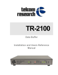
The TBS’s main window is the main interface for editing the databases,
collecting data, and generating reports. See Figure 1.
Figure 1 TBS
The following sections provide a brief outline of the TBS commands,
databases, and panes.
Optivity Telephony Manager
System Administration
Page 40 of 312
Telecom Billing System
Panes
The TBS displays its activities in the following panes:
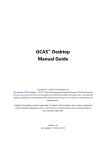
System Tasks pane
The System Tasks pane, shown in Figure 2, displays information about the
data collection, costing, and data transmission functions. Each tab in this pane
displays the data being processed, as well as the status of each process. Use
this pane to view the status of your data and of the system’s functions.
Figure 2 System Tasks pane
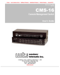
System Monitor pane
The System Monitor pane, shown in Figure 3, displays another view of
Collection, Costing, and Transmission activities. You can easily view the
status of a particular process and determine at a glance if the system is
running properly.
Figure 3 System Monitor pane
553-3001-331
Standard 3.00
August 2005
Telecom Billing System
Page 41 of 312
System Alarm pane
The System Alarm pane, shown in Figure 4, displays any alarm messages to
indicate any abnormal activity during the TBS session. It displays the alarm
messages for alarms that were defined in the System Configuration function.
When the system encounters an activity that surpasses a defined alarm
threshold, it displays the corresponding alarm in this pane. As well, this pane
displays all status messages for any running tasks with a severity level of
“Warning” or higher.
Figure 4 System Alarm pane
File menu
The File menu accesses functions used to archive, purge, and restore the Call
Database; import and export data; generate reports; and exit from the TBS.
To access these functions, click File from the main window, and then
select from the following menu options:
•
•
•
•
•
Call Database
— Archive
— Restore
— Purge
Import
Export
Reports
Exit
Optivity Telephony Manager
System Administration
Page 42 of 312
Telecom Billing System
Call Database
The Call Database menu option accesses another cascading menu containing
the Archive, Restore, and Purge menu options. These menu options access the
Archive, Restore, and Purge functions, which help you to manage your Call
Database records.
Archive
The Archive function is used to copy—or archive—a range of call records
from the Call Database to an external device, such as a network drive or a
disk.
Restore
The Restore function is used to copy—or restore—the archived call records
from an external device, such as a network drive, back to the Call Database.
Purge
The Purge function is used to delete—or purge—a range of call records from
the Call Database. This frees more disk space on your PC for new call records
and improves overall system performance.
Import
The Import function is used to import data records from an external source
to this system and convert them to a format compatible with the TBS
databases. This function is useful for quickly updating the TBS databases
with data from another application.
Export
The Export function is used to export data from the TBS databases to an
external source.
Reports
The TBS reports provide you with thorough and detailed information about
your telephone system. These reports detail and summarize your telephone
553-3001-331
Standard 3.00
August 2005
Telecom Billing System
Page 43 of 312
system’s usage, assign costs to the appropriate cost centers, and display
information on your system’s organizational databases. As well, they provide
statistics on your system to help assess the effectiveness of your telephone
services.
Figure 5 Reporting dialog box
Reporting options
The following options are used to select the output device for the report, as
well as its filters and sorting definitions. These options appear in the Profile
section (right side) of the Reporting dialog box, shown in Figure 5.
Output Type
The Output Type drop-down list box contains a list of output formats for the
selected report. You can select from the following options:
Screen: This option displays the report on the screen.
Optivity Telephony Manager
System Administration
Page 44 of 312
Telecom Billing System
Printer: This option prints the report to the Windows-configured printer.
Rich Text Format: This option exports the report to a file in rich text format
(RTF). Its filename is the name you entered in the File Name box as
extension.RTF.
HTML Format: This option exports the report to a file in hypertext markup
language format (HTML). Its filename is the name you entered in the File
Name box as extension.HTM.
Snapshot Format: This option exports the report to a file in Microsoft
Snapshot format. Its filename is the name you entered in the File Name box
as extension.SNP. To open the file in Snapshot format, you must have the
Snapshot Viewer installed on your PC.
File Name
When outputting a report to a format other than a printer or screen, the Report
Generator requires that you specify its filename and destination. This way, it
can save the report to a file in that selected format. In the File Name box, enter
the name of the file to which the report will be exported. Also select the
destination drive and directory for this file. This filename has an extension
that corresponds to the format of the file. This field is activated only if you
are exporting the report to a file in one of the supported formats (RTF,
HTML, or Snapshot).
Note that you can enter specific variable tags in your filenames to create
unique filenames during report generation. This provides you with added
flexibility when you are generating reports at scheduled intervals and you do
not want to rename the files for each interval.
Send File Using E-Mail
When generating a report to a file, you can also send copies of that file to
definable e-mail addresses. The Send File Using E-Mail option allows you
to e-mail a copy of the report to selected e-mail addresses. When you generate
the report, this option inserts the report file as an attachment to an e-mail
message. This option e-mails the outputted file that you entered in the File
Name box. Since this function inserts the report file as an attachment to an
553-3001-331
Standard 3.00
August 2005
Telecom Billing System
Page 45 of 312
e-mail message, it is available only if you are outputting a file to RTF or
Snapshot format.
Filter Definitions
The Filter Definitions function is used to select the reporting criteria for your
reports. This allows you to generate reports based on very specific
requirements. For example, you may want to view a report for only the
current day. You can simply use the Filter Definitions function to select the
most recent day for this report. You can then select this filter name from the
Filter drop-down list box in the main Report Generation dialog box when
you print the report.
Sort Definitions
The Sort Definition function is used to sort the data in the reports in different
formats. For example, you may want to display a report by date and time. You
can simply use the Sort Definition function to sort the report by the selected
date and time. You can then select this sort definition name from the Sort
drop-down list box in the Reporting dialog box when you print the report.
Reporting commands
The following is a list of the Report Generator commands:
Go: This command generates the selected report.
Schedule: This command schedules the report to be run at a later date and
time. This accesses the Scheduler application from which you can enter the
scheduling criteria for the report, including the initial date and time of the
report generation, as well as any subsequent intervals for generating the
report.
Cancel: This command exits from this function.
Help: This command allows you to obtain help on the Report Generator
function.
Optivity Telephony Manager
System Administration
Page 46 of 312
Telecom Billing System
Creating custom logos on reports
Each TBS report contains a common header graphic, which is located at the
top left corner of the report. This graphic helps you to easily identify the
reports as part of the TBS.
The TBS allows you to edit this graphic, or even replace it with another
graphic, by simply editing a bitmap (BMP) file. You can replace this graphic
with another more descriptive design, such as your company logo, to suit your
own needs. For example, you can include your company logo on your TBS
reports to provide you with professional-looking reports that are customized
for your organization.
Caution: Be careful when editing this graphic file. If the file is too large,
it may cause errors with the generated reports. To ensure that the original
graphic file is secure, you should make a backup copy of it. To do so,
copy the file Logo.bmp from the site/system directory to another
directory, or simply rename it (for example, Backup_Logo.bmp).
Perform the following steps to create a custom graphic or logo for your
reports.
1
Use a graphics program such as MS Paint to create a bitmap with the
following dimensions: 3.73" (W) by 0.86" (H).
2
Insert or create the new graphic (for example, your company logo)
in the bitmap file.
3
Save this file as Logo.bmp to the drive and directory for your site
and system (for example, C:\Nortel\Common Data\Sample
Site\Sample System\Logo.bmp).
To help you to use the correct dimensions for your logo, you can make a copy
of the original graphic file Logo.bmp and use it as a template for your own
graphic. Simply open the file Logo.bmp and insert the new graphic in the file.
The TBS reporting function automatically uses this logo on your reports.
553-3001-331
Standard 3.00
August 2005
Telecom Billing System
Page 47 of 312
List of reports
The following is a list of the reports that are available for the TBS.
Cost Analysis Reports
The Cost Analysis Reports display costing information for calls made by your
employees, either by their extensions or authorization codes. The tabulated
costs are then rolled up to their respective organizational level summaries.
Costs can also be identified by account codes and then charged back to your
clients.
The following is a list of the available Cost Analysis Reports:
•
•
•
•
•
•
•
•
•
•
•
•
•
•
•
•
•
Extension Detail Report
Extension Detail Report with Account Codes
Exception Chronological Report
Entity Detail Report
Dialed Number Info Service (DNIS) Summary Report
DNIS Detail Report
Auxiliary ID Detail Report
Authorization Code Detail Report
Account Code Summary Report
Account Code Detail Report with Employees
Account Code Detail Report
Entity Summary Graphs
Organization Roll-up Summary Graphs
Account Code Roll-up Summary Reports
Authorization Code Roll-up Summary Reports
Entity Roll-up Summary Reports
Extension Roll-up Summary Reports
Optivity Telephony Manager
System Administration
Page 48 of 312
Telecom Billing System
Directory Information Reports
The Directory Information Reports provide you with details about your
system’s corporate databases. Such reports as the role/project, external party,
and employee directory reports are useful in maintaining an up-to-date listing
of your projects, customers, and employees.
The following is a list of the available Directory Information Reports:
•
•
•
•
Role/Project Directory Report
External Party Directory Report
Employee Directory Report (ordered by Organizational Unit)
Employee Directory Report
Frequency Reports
The Frequency Reports provide details on actual telephone usage.
Management can isolate individual users and departments that are not
properly using the telephone system through misuse or neglect. As well,
system administrators can use this information to determine which services
are not being utilized. This analysis allows you to adjust your telephone
services to suit your needs.
The following is a list of the available Frequency Reports:
•
•
•
•
•
•
•
•
•
•
553-3001-331
Undisbursed Verification Report
Unanswered Calls Summary Report
Unanswered Call Detail Report
Ring Time Report
Ring Time Analysis Report
Location Summary Report
Hold Time Summary Graph
Hold Time Detail Report
Frequently Called Numbers Report
External Party Summary Report
Standard 3.00
August 2005
Telecom Billing System
•
•
•
•
•
•
•
•
Page 49 of 312
Duration Summary Graph by Call Type
Duration Summary Graph
Digits Detail Report
Call Area Summary Report
Area Code Summary Report
Area Code Location Summary Report
Area Code Summary Graphs
Location Summary Graphs
Surcharge Reports
The Surcharge Reports display costing information for calls made through
your system. They itemize the total usage charges by cost, surcharge (profit),
and total cost (billed amount). The tabulated costs are then rolled up to their
respective organizational level summaries. These costs are identified by the
associated authorization codes and extensions on the entity reports. The costs
can also be identified by account codes and then charged back to your clients.
The following is a list of the available Surcharge Reports:
•
•
•
•
•
•
•
Exception/Chronological Surcharge Report
Entity Surcharge Summary Report
Entity Surcharge Detail Report
Account Code Surcharge Summary Report
Account Code Surcharge Detail Report
Account Code Surcharge Roll-up Summary Reports
Entity Surcharge Roll-up Summary Reports
Utility Tools Reports
The Utility Tools Reports provide assistance in managing the telephone
configuration databases. These reports highlight features of your telephone
configuration that must be updated regularly to keep your network
management and fiscal reports accurate.
Optivity Telephony Manager
System Administration
Page 50 of 312
Telecom Billing System
The following is a list of the available Utility Tools Reports:
•
•
•
•
•
•
Trunk Diagnostic Report
Telephone Configuration Report
System Configuration Report
Extension Diagnostic Report
Authorization Code Diagnostic Report
Account Code Diagnostic Report
Traffic Reports
The Traffic Reports help to determine cost effective networking solutions by
critically examining the telephone system’s trunks and services.
The following is a list of the available Traffic Reports:
•
•
Trunk Group Utilization Graphs
Trunk Usage Reports
— Trunk Utilization Report
— Trunk Graph
— Trunk Detail Report
— Tandem Tie Summary Report
Custom Reports
The Custom Reports folder contains any custom reports that have been
created using the Custom Reports Utility. This utility is used to create and
build reports using the tables and data from the TBS databases.
Edit menu
The Edit menu accesses the TBS’s main databases. These databases contain
all of the information you need to run the TBS effectively for your
organization.
553-3001-331
Standard 3.00
August 2005
Telecom Billing System
Page 51 of 312
To access these databases, click Edit from the main window, and then
select from the following:
•
•
•
•
•
•
•
•
•
•
Organizational Hierarchy
Employees
External Parties
Roles/Projects
Asset Assignments
Telephone Configuration
Location Books
Rate Tables
Taxes
Call Database
Organizational Hierarchy
The Organizational Hierarchy Database contains the different structural
levels within your organization (for example, departments, divisions, and so
on). You can create up to 20 different levels in this hierarchy. The
Organizational Hierarchy and the Level editors are used to create, name, and
arrange these different organizational levels. The employees in your
organization are assigned to these levels. The cost summary reports can then
summarize the calling activity and associated usage costs by these levels.
Employees
The Employee Database contains information about your organization’s
employees that is relevant to the TBS. It includes such information as your
employees’ names, telephone extensions, authorization codes, and their
locations within the organizational hierarchy. This information is required to
cost and allocate telephone calls to the proper extensions and cost centers
within your organization.
Optivity Telephony Manager
System Administration
Page 52 of 312
Telecom Billing System
External Parties
The External Parties Database contains information about individuals or
companies with whom you have regular contact. It includes such information
as the external party’s name, address, telephone number, and account code.
Use this database to define the telephone numbers and optional account codes
for your customers and contacts so you can identify commonly called
telephone numbers on your detail and summary reports. This database can
also be used to maintain a list of your frequently called customers or clients.
Roles/Projects
The Roles/Projects Database contains information about the different roles or
projects that require reporting in the TBS. It is used to assign extensions,
authorization codes, account codes, or dedicated trunk groups to projects or
personnel for reporting purposes. For example, it can contain information on
individuals or companies who use dedicated extensions but are not included
in the Employee Database (for example, contract workers). It can also contain
information on projects that require dedicated extensions and, therefore,
require a name and organizational position for reporting.
Asset Assignments
This database defines how the different assets are assigned to the corporate
entities in the Employee, External Parties, and Roles/Projects Databases.
Telephone Configuration
The Telephone Configuration Database is the TBS’s main costing database.
It combines rate tables, location books, and carrier pricing templates to
calculate usage costs for the various trunk groups that are defined for the sites
in your organization. It also calculates additional fixed costs, which can be
added to the basic usage costs of these trunk groups. As well, it allows you to
assign various reporting groups to calls for the system’s detail and summary
reports.
When calls are made through the trunks in these trunk groups, the TBS uses
the Telephone Configuration Database to calculate their total costs. It can
then assign these costs to the appropriate extensions (and, therefore,
553-3001-331
Standard 3.00
August 2005
Telecom Billing System
Page 53 of 312
personnel), as well as any defined organizational hierarchy levels within your
company.
The following is a summary of some of the features of the Telephone
Configuration Database:
•
•
•
•
You can define multiple telephone configurations, call digit
translations, and carrier pricing templates. This allows you to set up
multiple costing scenarios for a specific location, and then compare
rates from different carriers based on your telephone usage patterns.
This way, you can find out the true savings of using different
carriers.
This single editor allows you to define multiple telephone
configurations, and easily assign any predefined call digit
translations and carrier pricing templates to them.
The Telephone Configuration navigation tree allows you to easily
view your configuration information for each system. Therefore,
you can easily make any corrections to your configuration for all of
your systems.
The Bill Party Surcharge function is used to define and apply
additional charges to calls over and above the standard charges
calculated using the Telephone Configuration Database. These
surcharges are assigned to bill (or call) parties—typically, the
extension from which the call was placed, rather than the trunk line
over which the call was transmitted. This feature is used primarily in
the hospitality and campus billing market where the TBS can be
used to bill guests and other users.
Optivity Telephony Manager
System Administration
Page 54 of 312
Telecom Billing System
Figure 6 is an example of the Telephone Configuration Database editor:
Figure 6 Telephone Configuration Database editor
Location Books
The Location Books function is used to define the location books
(distance-based, latitude and longitude, and non-distance-based), and virtual
private network books, which are used by the TBS. Location books serve two
purposes in calculating costs for the TBS. Their first and primary purpose is
to find a meaningful location name for the source and destination of a phone
call. The second purpose is to obtain additional rating information, which is
used to determine the cost of a call. That is, it identifies the physical or virtual
locations of calls so that the TBS can apply the appropriate usage costs to
them based on their distance or codes.
553-3001-331
Standard 3.00
August 2005
Telecom Billing System
Page 55 of 312
Rate Tables
The TBS includes a set of common rate tables provided by different
telecommunications carriers. These rate tables provide the TBS with the
required rates and coverage areas used to identify how the calls to different
locations are costed. This way, the TBS knows which calls are costed with
which rates. Simply select these predefined rate table files from the
Telephone Configuration Database.
In most cases, you do not need to edit these rate tables. Your supplier can
provide you with the latest rate tables as they are updated. If, however, you
want to review or modify the rate tables included with the TBS, or if you want
to create new rate tables, then use the Rate Table editor to do so.
Taxes
The Tax Definition editor is used to define the taxes that are applied to the
telephone usage costs for your system. For example, if you want to add a sales
tax to all usage costs calculated for the main node, then enter this tax value in
this editor. You can then select it from the Tax Information fields of the Node
Information editor. If your system requires compound taxes, then you must
calculate them first, and then enter the resulting value in these fields.
Call Database
The Call Database editor is used to display and edit the call records stored in
the Call Database. The Call Database contains all of the call records that have
been collected from the switch. In some cases, it may be necessary to edit or
delete some call records (due to invalid fields, such as corrupted dates or IDs).
This allows you to remove bad or unwanted sections of the database or
replace invalid dates with valid dates.
View menu
The View menu contains commands that are used to display or hide the TBS’s
graphical toolbar and status bar. As well, you can clear the contents of the
Alarms pane and select the data to be displayed in the System Tasks pane.
Optivity Telephony Manager
System Administration
Page 56 of 312
Telecom Billing System
To access these functions, click View from the main window, and then
select from the following menu options:
•
•
•
•
Toolbar
Status Bar
Clear Alarms Pane
Settings
Tools menu
The Tools menu accesses the commands that manage the TBS’s main
processes. Use these commands to start, stop, schedule, and configure the
data collection, call costing, and data transmission processes.
To access these commands, click Tools from the TBS main window, and then
click the following menu options. Note that you can also click the
corresponding icons in the toolbar.
Collection
The Collection menu accesses the functions that manage the data-collection
process.
Start Collection: Starts the data collection in either batch or real-time mode.
Stop Collection: Stops the data collection process.
Schedule Collection: Accesses the Scheduler to schedule data collection at
a later date and time.
Configuration: Defines the parameters used by the TBS to communicate
with and collect data from the CS 1000M, CS 1000S, or Meridian 1 system.
Costing
The Costing menu accesses the functions that manage the call costing
process.
553-3001-331
Standard 3.00
August 2005
Telecom Billing System
Page 57 of 312
Start Costing: Starts the call costing process.
Stop Costing: Stops the call costing process.
Schedule Costing: Accesses the Scheduler to schedule call costing at a later
date and time.
Configuration: Defines the costing parameters in the Telephone
Configuration Database.
Transmission
The Transmission menu accesses the functions that manage the data
transmission process.
Start Transmission: Starts data transmission in real-time or batch mode.
Stop Transmission: Stops the data transmission process.
Schedule Transmission: Accesses the Scheduler to schedule data
transmission at a later date and time.
Configuration: Defines the parameters used by the TBS to communicate
with and transmit data to an external source, such as a Property Management
System (PMS).
Options menu
The Options menu accesses the System Configuration function. To access
this function, click Options > System Configuration from the main window.
System Configuration
The System Configuration function allows you to set up system options,
data collection and transmission parameters, and alarm thresholds.
System Tab: This tab contains processing parameters for the call records.
Optivity Telephony Manager
System Administration
Page 58 of 312
Telecom Billing System
Collection Tab: This tab contains the connection and communications
parameters for data collection.
Transmission Tab: This tab contains the connection and communications
parameters for data transmission, as well as the transmission setup
configuration.
Alarms Tab: This tab contains any alarm thresholds and their corresponding
alarm messages. These messages appear in the System Alarms pane of the
main window.
Setup Transmission Record Format Fields
The Available Fields list box in the Transmission tab contains all of the
fields you can select for your record format. The Selected Fields list box
contains all the fields you selected from the Available Fields list box (see
Figure 7). These fields will be included in the output stream during data
transmission.
553-3001-331
Standard 3.00
August 2005
Telecom Billing System
Page 59 of 312
Figure 7 Setup transmission record
The following is a list of the field names that you can select.
Billing Extension: This is the extension that is billed for the call. On an
outgoing call, this is the extension that placed the call. On an incoming call,
it is the extension that received the call.
Call Trunk: This is the trunk that carried the call.
Billing Trunk (Tandem Only): On a tandem call, two trunks are involved in
the call. The TBS creates two charge records, one for the incoming call on the
originating trunk and the other for the outgoing call on the terminating trunk.
When rating the incoming call, the originating trunk is considered to be the
Call Trunk because it is the one carrying the inbound traffic. The terminating
trunk is the Billing Trunk because it can be used through the Corporate
Directory trunk assets for billing back to a corporate entity. Conversely,
when rating the outgoing call, the terminating trunk is considered to be the
Call Trunk because it is the one carrying the outbound traffic. The originating
Optivity Telephony Manager
System Administration
Page 60 of 312
Telecom Billing System
trunk is the Billing Trunk because it can be used via the Corporate Directory
trunk assets for billing back to a corporate entity.
Call Type (N=Normal, I=Internal, T=Tandem): A Normal call designation
is given to an outbound or inbound call involving an on-net party and an
off-net party (for example, either the originating ID or the terminating ID is
an extension, and the other ID is a trunk). An Internal call designation is given
to calls involving two on-net parties (for example, both originating and
terminating IDs are extensions). A tandem call involves two off-net parties
(for example, both originating and terminating IDs are trunks).
Calling Direction (O=Outbound, I=Inbound): An outbound call is one
placed by an on-net party (an extension) to an off-net party (for example, a
trunk is used to reach the off-net party). An inbound call is a call coming from
an off-net party (for example, a trunk carries the call into the switch) that
terminates at an extension.
Originating ID Type (D=Extension, T=Trunk): This designates whether
the originating party of the call is a trunk or an extension.
Originating Extension/Trunk: This is the actual identifier for the
originating party (for example, the specific extension or trunk number of the
originating party).
Terminating ID Type (D=Extension, T=Trunk): This designates whether
the terminating party is a trunk or an extension.
Terminating Extension/Trunk: This is the actual identifier for the
terminating party (for example, the specific extension or trunk number of the
originating party).
Date: This is the date on which the call was made.
Time: This is the time of day at which the call was made.
Billed Duration: This is the duration of the call used for billing. This is the
actual duration of the call rounded according to the specified rounding
parameters set by the carrier.
Duration: This is the actual duration of the call in seconds.
553-3001-331
Standard 3.00
August 2005
Telecom Billing System
Page 61 of 312
Digits Dialed: These are the digits dialed that were recorded and output by
the switch in the CDR stream.
Formatted Digits Dialed: These are the digits formatted after processing by
the costing function according to its call digit translation, access codes, and
carrier pricing templates.
Digits as Costed: These are the digits that were used by the costing function
to determine the call location and carrier pricing. These are the original digits
dialed after call digit processing and access code removal by the costing
function.
Account Code: This is an additional code dialed on a call for charge-back
purposes, often used by legal, accounting, and consulting firms to identify a
specific client for charge back.
Authorization Code: This is an additional code dialed on a call to authorize
and identify the individual placing the call. This is often used in campus
environments when calls need to be placed from anywhere within the
campus.
Calling Line ID (CLID): This identifies the telephone number of the calling
party on an inbound call.
Dialed Number Info Service (DNIS): This identifies the number dialed by
the calling party to reach the company.
Area Code & Exchange (NPANXX): This is the North American
numbering plan area code and exchange dialed on the call. On non-North
American calls, this field contains the dial code of the location that matched
the digits/CLID on the call. This is used when looking up the call’s location
in the location book specified in the Telephone Configuration Database.
Location: This is the city name of the called/calling location, which is looked
up in the specified location book using digits/CLID on the call.
Province/State: This is the province or state name of the called/calling
location, which is looked up in the specified location book using digits/CLID
on the call.
Optivity Telephony Manager
System Administration
Page 62 of 312
Telecom Billing System
Country: This is the country name of the called/calling location, which is
looked up in the specified location book using digits/CLID on the call.
Route: This is the route designation for the call specified by the Telephone
Configuration Database.
Call Cost: This is the basic cost of the call as determined by the Telephone
Configuration Database before surcharging.
Tax on Call Cost: This is the total tax charged on the above-listed Call Cost
according to the taxes specified in the Telephone Configuration Database.
Call Cost + Taxes: This is the sum of the above-listed Call Cost and Tax on
Call Cost values.
Surcharge: This is the surcharge applied to the call according to the
Surcharging parameters specified in the Telephone Configuration Database.
Tax on Surcharge: This is the tax amount on the surcharge calculated
according to the taxes specified in the Telephone Configuration Database.
Call Cost + Surcharge: This is the Call Cost plus the Surcharge without
taxes.
Tax on (Call Cost + Surcharge): This is the total tax on the Call Cost and
Surcharge.
Call Cost + Surcharge + Taxes: This is the total of the above-listed Call
Cost and the Surcharge values and the taxes on those values.
Tax 1, Tax 2, Tax 3 & Tax 4: Up to four different taxes can be specified in
the Telephone Configuration Database. These fields contain the tax amount
calculated on the above-listed Cost value plus the Surcharge value for the four
specified taxes.
Off End Taxes: This is the tax applied to any charges that have gone off end
from a tie-line node programmed in the Telephone Configuration Database.
User Defined: The User Defined value is any constant value that you wish to
include in a specific location of the output data stream during data
553-3001-331
Standard 3.00
August 2005
Telecom Billing System
Page 63 of 312
transmission. For example, the standard HOBIC record format for hotels may
require a 3-letter hotel ID column, which you can enter in the User Defined
field as a constant value (for example, HB1). This value is included in the
record that is sent to a downstream property management system. When you
select User Defined, it uses the constant value that you entered in the Sample
Value field (located next to the selected fields list). As with the other fields
defined in the data transmission, you can select multiple User Defined fields
and position them at any location in the record.
TBS Display option
The TBS Display option for collecting, costing, and transmitting call records
negatively impacts system performance by consuming system resources.
Disabling the Display option
To improve system performance, disable the TBS Display option:
1
In the TBS application, select View > Settings, as shown in Figure 8
on page 64.
Optivity Telephony Manager
System Administration
Page 64 of 312
Telecom Billing System
Figure 8 TBS
The Settings dialog box opens with the Collection tab selected. See
Figure 9.
553-3001-331
Standard 3.00
August 2005
Telecom Billing System
Page 65 of 312
Figure 9 Settings dialog box—Collection tab
2
Ensure that the Display CDR records as they are collected check
box is cleared.
3
Click the Costing tab.
Optivity Telephony Manager
System Administration
Page 66 of 312
Telecom Billing System
The Settings dialog box—Costing tab appears. See Figure 10.
Figure 10 Settings dialog box—Costing tab
553-3001-331
4
Ensure that the Display Call Records as they are costed check box
is cleared.
5
Click the Transmission tab.
Standard 3.00
August 2005
Telecom Billing System
Page 67 of 312
The Settings dialog box—Transmission tab appears. See Figure 11.
Figure 11 Settings dialog box—Transmission tab
6
Ensure that the Display Call Records as they are transmitted
check box is cleared.
7
Click OK.
Getting started
This section describes how to access the TBS and set it up for initial use. Use
the following instructions and examples to configure the TBS to collect and
process the CDR records that are output from your system.
This section includes:
•
•
An overview of a call record and how the TBS applies costs to it
The options that you must activate in the system to allow for CDR
data collection
Optivity Telephony Manager
System Administration
Page 68 of 312
Telecom Billing System
•
•
•
•
How to connect and set up a CDR buffer unit, specifically the
MDR-2000 Intelligent Storage Device (ISD)
How to run the TBS for a system
How to set up and start data collection for the TBS
How to set up the TBS Telephone Configuration Database
(including entering node information, rate tables, and location
books)
The following instructions and examples are intended to assist you in setting
up the TBS for your own configuration. Since each telephone system is
configured differently and each OTM installation is different, these examples
cannot predict every scenario. You should, therefore, use these examples to
teach yourself how to set up your hardware and configure the TBS software
to work with this hardware. These examples are designed to account for the
majority of cases and provide you with valuable assistance in getting started.
Before using the TBS, you must install and configure it as part of the OTM
system. Refer to Optivity Telephony Manager: Installation and
Configuration (553-3001-230) for complete details on installing the TBS as
part of OTM and assigning it to a site and a system.
Overview of a call record
Before you enter your system configuration and update your TBS databases,
you should first understand the nature of the data that is output from the
system. This will help you to construct your system configuration databases
to match your system. This section describes the components of a call record
as well as how it is processed and costed by the TBS.
CDR call records, which are output from the system and are collected by the
TBS, contain the key information to producing costing reports. The following
is a summary of what happens to a call record:
System outputs call records
When a user places or receives a telephone call, the system records its
information as a CDR record (call record). This record contains such
information as the call’s start date and time, its duration, the trunk it went out
on, its associated line, and the digits dialed. This data is sent to the system’s
553-3001-331
Standard 3.00
August 2005
Telecom Billing System
Page 69 of 312
Serial Data Interface (SDI) port. From here, an application or hardware
device must record it so it can be processed. This can be a buffer unit that is
connected to the system’s SDI port (recommended), or even a PC running the
TBS for a direct connection.
As call records are output from the system, the TBS collects this data either
through a buffer unit, such as the MDR-2000 ISD, or directly to the PC.
Buffer units are recommended for collecting CDR data since they can
continuously collect and safely store these call records. A buffer unit is
portable enough to be located close to the system. Some may also have
security features to allow for safe data storage (for example, battery backups).
Whichever way you decide to collect the call records, remember that unless
something is collecting the call records output from the system, they will be
lost.
Figure 12 displays the movement of a call record from the system through a
buffer unit to the TBS software program on a PC. Notice that modems can be
used to communicate with the system and buffer units from distant locations.
Figure 12 System block diagram
Figure 12 represents a single “system.” This system usually represents a
CS 1000 or Meridian 1 system or a physical location in the TBS software and
contains the actual database files for it. Before attempting to use the TBS, you
must add it as an application to the appropriate system.
Optivity Telephony Manager
System Administration
Page 70 of 312
Telecom Billing System
Figure 13 is an example of how the sample system is set up.
Figure 13 Sample system setup
The TBS collects call records
The TBS collects call records from the system through the buffer unit, and
formats and appends them to the end of the Call Database. The Call Database
is an indexed collection of call records that reflects the calling activity of the
system.
Figure 13 on page 71 is a breakdown of the information found in each call
record. Notice how the TBS databases use each component of the call record:
553-3001-331
Standard 3.00
August 2005
Telecom Billing System
Page 71 of 312
Figure 14 Sample call record allocation
Processing X (transferred) records
Your CS 1000 or Meridian 1 can be programmed to output transferred call
records (also known as X records) as individual call records. Where required,
you can set up the TBS to process and report on these X records. For example,
you may want to more accurately identify calling activity within the different
departments in your organization. Note that this option affects call volumes
and, therefore, makes any costing based on volume plans inaccurate.
With this option enabled, call records representing calls that have been
transferred are broken down into individual call records based on the call
transfer. For example, an incoming call that has been transferred once,
becomes two call records. The first call record is identified as an incoming
call to a specific extension. The second call record is identified as an internal
call from the first extension to the second extension. If this option is disabled,
then this is only identified as a single call record.
Optivity Telephony Manager
System Administration
Page 72 of 312
Telecom Billing System
To set up the TBS to process X records, you must edit the Script
Configuration initialization file (ScriptConfig.ini). This text file, located in
your site/system directory (for example, C:\Nortel\Common Data\Sample
Site\Sample System\), identifies how the X records are processed. By default,
it is set to not process X records.
The following is an example of this file (with the ProcessXRecords
option set to NO):
[SL1NEW]
ProcessXRecords=No
To change its settings so that the TBS can process X records, open the
file using a text editor such as MS Notepad, and change the text to read
as follows:
[SL1NEW]
ProcessXRecords=Yes
Save this file and run the TBS to process these records. You are prompted
with a warning message stating that X records are being processed.
For real-time CDR collection of X type records, select the script
SL1NEW.COL. To collect these records from an MDR-2000 ISD, select the
script M2KIMG_SL1NEW.COL. For more information on these scripts,
refer to Appendix , “Appendix A: Scripts,” on page 249.
Processing B (Abandoned call) records
With International Release 18 Group H and North American Release 20, B
(Abandoned call) records are output when the Time to Answer feature is
active and New format CDR is selected for CDR TTY output (FCDR = NEW
in LD 17). B records are only output to CDR – Teletype devices.
B records are output when:
•
553-3001-331
an unanswered incoming trunk disconnects and ABAN = YES in
LD 16
Standard 3.00
August 2005
Telecom Billing System
•
Page 73 of 312
internal CDR is equipped and an unanswered internal station
disconnects from another internal station which has ABDA class of
service
Prior to Release 23, the CDR B record provided information only for
abandoned calls on ringing. With the Release 23 feature CDR on Busy Tone,
a B record is produced when the originator of an incoming or internal call
disconnects after receiving a busy tone. The CDR on Busy Tone B record
information is displayed on the third line of the CDR B record for customers
with the New CDR format (FCDR) configured.
For real-time CDR collection of B type records, select the script
SL1NEW.COL. To collect these records from an MDR-2000 ISD, select the
script M2KIMG_SL1NEW.COL. For more information on these scripts,
refer to Appendix , “Appendix A: Scripts,” on page 249.
The TBS costs call records
Once the TBS collects the call records, it runs them through a series of
calculations to apply costs to them. It then stores these costed call records in
the Call Database. Each process uses the parameters stored in the Telephone
Configuration Database (you will see how to configure these later in this
chapter).
The following is a summary of how the call records are processed:
1.The Call Digit Translation table of the Telephone Configuration Database
translates the digits dialed to remove or edit any access codes.
2.The TBS looks up the trunk on which the call went out to see which service
definition to check. It looks this up in the table of the Telephone
Configuration Database’s Service Definition.
3.The TBS applies any minimum call duration and network connect time
adjustment values to the call.
4.The TBS identifies the Carrier Pricing Template assigned to the trunk. This
indicates the type of call, how the number should be formatted on the report,
and which rate structure should be used to cost the call.
Optivity Telephony Manager
System Administration
Page 74 of 312
Telecom Billing System
5.The TBS applies any fixed costs to the call.
This completes the overview of how the TBS processes a call record.
Setting up the TBS: Example scenario
The example setup is based on the following scenario:
•
•
•
•
•
The Acme Company has its head office located in Dallas, Texas.
The telephone number for its head office is (214) 555-1111.
The telephone system requires that users enter the access code “9”
before making any outgoing calls.
There is one trunk route with 46 members on the Meridian 1. These
are configured as trunks 2001 to 2046.
The Meridian 1 that is located in the switch room of the Acme
Company head office building requires an MDR-2000 ISD to collect
CDR data. A modem is attached to it to allow for communications
between it and a PC in another room. It has a dedicated extension
number of 222.
The PC on which the TBS is installed is located in another room of
the same building. A modem is attached to this PC's COM1 port and
is used to connect to the MDR-2000 ISD.
Setting up the TBS: Summary
The following is a summary of the steps required to set up and configure
the TBS to process call records. You need to perform these steps only
when you first install and use the TBS or if your configuration or
hardware changes:
1.Ensure that the system is set up to properly output CDR data.
2.Install and set up the buffer unit.
3.Install any rate tables purchased for your dialing plan.
553-3001-331
Standard 3.00
August 2005
Telecom Billing System
Page 75 of 312
4.Run the TBS so it can be configured.
5.Set up and test the data collection process before running it in a real-time
situation.
6.Obtain the List Trunk and Member (LTM) values from the Meridian 1.
7.Set up the telephone configuration.
8.Test the telephone configuration.
For more details on each of the TBS functions and features described in the
following sections, refer to the online Help included with the TBS. For more
details on the hardware components included with the OTM TBS (for
example, buffer units, modems), refer to their associated documentation.
Step 1: Ensure that the system is set up properly
For the TBS to collect and process CDR data, the system must output the data
in the proper format. You must, therefore, enable the required features and
options in the system overlays. This section describes the options that are
required for the TBS to process the CDR data.
Note: This document is not intended to describe all
options related to CDR data. For complete details on the
available CDR options and information on configuring
CDR, see Call Detail Recording, Description and
Formats (553-2631-100) in the Meridian 1
documentation library.
Select CDR output format
1
In LD 17, select either NEW or OLD format CDR output
(FCDR=NEW). The TBS contains script files for supported buffer
units, including the MDR-2000 ISD. As well, it can be configured to
support both NEW and OLD CDR formats.
Optivity Telephony Manager
System Administration
Page 76 of 312
Telecom Billing System
Auxiliary Identification output in CDR record
2
In LD 15, configure the Auxiliary Identification to be output in CDR
(AXID=Yes). The AXID field is not captured by the TBS, but is
required to ensure that data fields output in the CDR record appear
in the expected positions.
Configure routes for CDR output
3
In LD 16, configure the routes that output CDR data (CDR=Yes),
and determine the type of CDR data to output. For example, you
may want to record all incoming calls and only outgoing toll calls.
4
Ensure that the SDI port for your system is configured to match the
settings on the buffer unit. If you plan to collect data at a higher
baud rate, you may need to change both the SDI port and the buffer
unit settings.
The default settings for the MDR-2000 ISD are:
•
•
•
•
Baud = 1200
Data Bits = 8
Parity = None
Stop Bits = 1
If you plan to use the default values for the MDR-2000 ISD, you must use the
same values for the SDI port.
Step 2: Install and set up buffer unit
The TBS collects CDR data from the system either directly or through one of
several types of buffer units. Based on your configuration, you may need to
collect the CDR data from a buffer unit in a specific format and share it
between different applications.
For this setup, assume that the TBS is collecting CDR data from the
MDR-2000 ISD. This section describes how to connect the MDR-2000 ISD
to the system and the PC via a modem connection. This provides you with an
553-3001-331
Standard 3.00
August 2005
Telecom Billing System
Page 77 of 312
example by which you can learn how to set up the other OTM-supported
buffer units. Since other buffer units have different connection and
communications requirements, you should refer to their documentation for
more details on setting them up.
Security precautions for MDR-2000 ISD
The MDR-2000 ISD is a precision electronic product. Remember to review
all of the documentation included with the MDR-2000 ISD before attempting
to install and use it. Failure to observe the precautions and guidelines outlined
in the documentation may lead to product failure, damage, and invalidation
of all warranties.
Before handling the MDR-2000 ISD, take all proper electrostatic
discharge (ESD) precautions, including personnel and equipment
grounding:
•
•
•
•
Do not rest the MDR-2000 ISD on the power cord. A damaged
power cord can cause fires or electrical shocks.
Do not use the MDR-2000 ISD in damp, dusty, or dirty places.
Store spare components in proper antistatic material.
Make sure equipment is turned off before handling or changing
components.
Caution: ESD damage is not always immediate and can result in failures
after months of operation.
Connect MDR-2000 ISD to system and PC
The first step is to connect and install the MDR-2000 ISD onto the system. It
can then collect and store call records as they are output from the system. You
must then connect the PC to the MDR-2000 ISD so the TBS can collect the
call records from its database files. For this example, you configure and
connect modems to the MDR-2000 ISD and to the PC.
Optivity Telephony Manager
System Administration
Page 78 of 312
Telecom Billing System
Perform the following steps to connect the MDR-2000 ISD to the
system, and then to the PC via a modem connection.
1
Locate the system’s SDI port.
2
Connect the MDR-2000 ISD to the system’s SDI port using an
RS-232C cable. See Figure 15 on page 79:
a
Connect one end of the RS-232C cable to the PBX port on the
MDR-2000 ISD, and the other end to the SDI output port on the
system.
b
Use a male DB-25 connector when connecting to the PBX port
of the MDR-2000 ISD.
Figure 15 Meridian 1 to MDR-2000 ISD
3
4
553-3001-331
Connect the MDR-2000 ISD to the first modem:
a
Connect the null modem cable, which is provided with the
MDR-2000 ISD, from the Modem port of the MDR-2000 ISD to
the serial port of the modem.
b
Connect a telephone line cord from the “To Line” output jack of
the first modem to the telephone jack.
Connect the PC to the second modem. See Figure 16 on page 80.
Standard 3.00
August 2005
Telecom Billing System
Page 79 of 312
a
Connect a modem cable from an available communications port
(for example, COM 1) on the PC to the serial port of the second
modem. If you have an internal modem attached to your PC,
ignore this step.
b
Connect a telephone line cord from the “To Line” output jack of
the second modem to the telephone jack.
Figure 16 MDR-2000 ISD to modems to PC
5
6
Plug in and turn on the MDR-2000 ISD:
a
Plug in the MDR-2000 ISD’s AC adapter into the electrical
outlet.
b
Insert the AC power supply connector into the 9 VDC jack of
the MDR-2000 ISD.
Plug in and turn on the modems:
a
Plug in the modems’ AC adapters into the electrical outlets.
b
Insert the AC power supply connector into the power jack of the
modem.
Optivity Telephony Manager
System Administration
Page 80 of 312
Telecom Billing System
7
Test the MDR-2000 ISD to ensure that it is collecting data. Once
you have turned on the MDR-2000 ISD, all the lights flash briefly
and the RUN and BMT indicators remain on. After the second valid
call record is obtained, only the RUN indicator remains on. The first
valid call is used to populate the buffer registries when the
MDR-2000 ISD has been turned off and on.
The PBX indicator flashes as the MDR-2000 ISD receives data.
This indicates that the data stream is being received. If the PBX light
does not flash and you are sure that a call has been made, check the
following:
•
•
If you require a null modem adapter between the system and the
MDR-2000 ISD, then ensure that it is connected between the
system’s SDI port and the PBX port of the MDR-2000 ISD.
Ensure that CDR is turned on for the trunk route you are using.
Verify that the MDR-2000 ISD is collecting data
Access the MDR-2000 ISD to view and verify that the incoming data
stream is valid. To access the MDR-2000 ISD, perform the following
steps.
553-3001-331
1
Run a terminal program such as Windows HyperTerminal.
2
Dial up the telephone number of the MDR-2000 ISD. This is the
number where the MDR-2000 ISD was connected via its modem. If
the PC is connected directly to the MDR-2000 ISD, then you can
simply start typing the commands to edit the parameters. For this
example, enter 222.
3
Type <Ctrl-V> I D <Enter>. This verifies that you are
communicating with the MDR-2000 ISD. The response is the serial
number of the MDR-2000 ISD.
4
To view the data, type <Ctrl-V> D U <Enter> (you may need to
type this twice). If the data appears incorrect (for example, it
contains random characters), then there is probably a
communications problem.
Standard 3.00
August 2005
Telecom Billing System
Page 81 of 312
Changing communications parameters
The MDR-2000 ISD default communications parameters may be different
from the CS 1000 or Meridian 1 system. For example, the MDR-2000 ISD
baud rate defaults to 1200, and the system may be 9600. If they are different,
you must change the communications parameters of one or the other.
The following example demonstrates how to change the communications
parameters of the MDR-2000 ISD and also set it for NEW CDR format. If you
want to change the communications parameters on the system, refer to the
documentation provided with it.
To change the MDR-2000 ISD’s communications parameters, access the
MDR-2000 ISD interface using any terminal program running directly
from your PC. The following example demonstrates this process.
1
Run a terminal program such as Windows HyperTerminal.
2
Dial up the telephone number of the MDR-2000 ISD (for example,
222). This is the number where the MDR-2000 ISD was connected
via its modem. If the PC is connected directly to the MDR-2000
ISD, then you can simply start typing the commands to edit the
parameters.
3
Access the MDR-2000 ISD interface by typing <Ctrl-V> I M
<Enter>. The M2K> prompt appears.
4
Check the status of the MDR-2000 ISD by typing ST <Enter>.
The status appears similar to Figure 17.
Optivity Telephony Manager
System Administration
Page 82 of 312
Telecom Billing System
Figure 17 MDR-2000 ISD status
5
To change the baud rate for the modem port on the MDR-2000 ISD
to 9600, type SE BA <Enter> 9600 <Enter>. This responds as
SE (Set Options) BA (Baud) PBX (PBX default) 9600. The first
<Enter> in this line selects the default baud rate for the PBX port on
the MDR-2000 ISD.
6
To quit and exit from this interface, <Enter> Q (quit).
Note: If you are changing the baud rate for the modem,
ensure that the modem answers at the desired speed first.
For example, if you are using the Windows
HyperTerminal program to access the modem, it
prompts Connect 9600 when you are connected.
553-3001-331
Standard 3.00
August 2005
Telecom Billing System
Page 83 of 312
Note: Once you have completed accessing the
MDR-2000 ISD, remember to exit from it by typing Q
(quit). If your communications session is interrupted
(for example, by a disconnected line or a power failure),
then you lose your edits.
Notes for customization strings
In certain cases, you may need to change the customization strings of the
MDR-2000 ISD to match the output of the system. If you need to change the
customization strings, use the CU (Customize) command in the MDR-2000
ISD interface and change the strings as necessary. Refer to the documentation
provided with the MDR-2000 ISD for more details on what the customization
strings represent.
Step 3: Install rate tables and location books
Before you configure the TBS, you must install the rate tables that reflect
your telecommunications provider’s rates. These provide such rates as
long-distance calls charges for direct dialed calls to North America, as well
as international long-distance charges. The TBS requires these rate tables to
accurately apply costs to your long-distance calls.
As well as rate tables, you must install a set of location books for your
software. Location books contain codes for the actual locations that are used
by the rate tables to determine the charges incurred when calling these
locations.
You can obtain rate tables from a rate service or from your dealer. Remember
that the rate table files must be compatible with the TBS software. If in doubt,
check with your supplier before purchasing any rate tables.
To install the rate tables and location books, simply follow the instructions
included with them. Remember to install the rate table files onto your OTM
TBS directory so you can select the appropriate rate table files when you are
defining your carrier pricing templates.
Optivity Telephony Manager
System Administration
Page 84 of 312
Telecom Billing System
Step 4: Run TBS so it can be configured
If OTM is not already running, click OTM Navigator from the StartUp
program group. In the OTM Navigator, open a predefined site and system
(for example, Site=Acme Company, System=Head Office).
Once you open the site and system, the window shown in Figure 18 appears.
Figure 18 OTM Navigator
From the selected site and system in the OTM Navigator, click
Telemanagement, and then click TBS.
This accesses the TBS application main window, as shown in Figure 19 on
page 86, from which you can set up the communications parameters,
telephone configuration, and rate tables for initial use. You must also test the
data collection and run reports to see if the data was collected and costed
properly.
When you first run the TBS for a specific site and system, the Telephone
Configuration Wizard appears. This allows you to optionally enter a basic
telephone configuration for this site and system. Since you are not using the
553-3001-331
Standard 3.00
August 2005
Telecom Billing System
Page 85 of 312
Telephone Configuration Wizard to enter your configuration, leave these
fields blank and click OK to access the TBS.
Figure 19 TBS main window
Step 5: Set up and test data collection
Before you enter your telephone configuration, you should verify that the
TBS is collecting data from the system in the correct format. This way, you
can test the configuration against actual calls. To test the data collection,
simply enter the data collection parameters, collect the call records from the
system, and view them in the Call Database.
Enter data collection parameters
For the TBS to collect data from the system, you must enter the data
collection parameters for the site and system. You should have already
connected and configured your hardware (see previous sections entitled “Step
1: Ensure that the system is set up properly” and “Step 2: Install and set up
buffer unit”). You need to access the System Configuration function’s
Communications tab only to select the communications and data collection
parameters.
Optivity Telephony Manager
System Administration
Page 86 of 312
Telecom Billing System
In this example, you are collecting data from the Meridian1 or CS 1000S
system through the MDR-2000 ISD buffer unit. Note that you can also collect
data from other buffer units. You can also collect data directly from the
system using a direct connection or from the DBA application (network
connection).
For more information on setting up the TBS to collect data from the OTM
DBA application, refer to the section entitled: “Setting up TBS to collect data
from OTM DBA Application” on page 165.
To enter the data collection parameters for the TBS, perform the
following steps.
1
From the TBS main window, click Options > System
Configuration. The System Configuration dialog box appears.
2
Click the Collection tab and enter your communications and
collection parameters. For example, enter the following values:
•
•
•
•
•
•
•
•
3
553-3001-331
Type: Dial-Up
Phone No: 222
Redials: 3
Port: COM1
Baud Rate: 9600
Data Bits: 8
Parity: None
Stop Bits: 1
In the Collection Script box, enter the name of the script file that is
used for this data collection. This file contains the instructions used
to communicate with the buffer unit and collect data from it. The
script filename you select depends on the type of buffer unit and the
format of the data being collected. For example, if you are collecting
data from the MDR-2000 ISD, then select MDR2000.COL. Refer to
“Telecom Billing System (TBS) scripts” on page 249 for a list of
supported buffer units and their corresponding script filenames.
Standard 3.00
August 2005
Telecom Billing System
Page 87 of 312
In certain cases, you may want to report on transferred call records
(also known as X records) and on Abandoned calls (also known as B
records). With the X record option, call records representing calls
that have been transferred are broken down into individual call
records based on the call transfer. For more information on reporting
on X and B records, refer to the sections, “Processing X
(transferred) records” on page 72 and “Processing B (Abandoned
call) records” on page 73. Note that X records cannot be processed if
you are collecting data from the MDR-2000 ISD.
4
Click OK to select these options and return to the TBS main
window.
Test data collection
Now that you have configured your hardware and entered the required
communications parameters, you are ready to test the data collection. At this
stage, you should only run a data collection as a test. Later, you can set up and
invoke data collection once you have entered all of your system information
and you are ready to run it live.
The following is an example to demonstrate how to test the data
collection process. This example assumes the following:
•
•
•
The system is outputting CDR data to the SDI port.
The MDR-2000 ISD is directly connected to the system and is
continuously collecting and storing the raw CDR data (call records)
as they are output from the system.
The TBS collects this CDR data from the MDR-2000 ISD and stores
it in the Call Database.
To test the data collection for this scenario, perform the following steps.
1
Wait for some calls to be recorded by the system. Either wait for
some calling activity on the system or make a few telephone calls. If
the MDR-2000 ISD is properly connected to the system, it collects
Optivity Telephony Manager
System Administration
Page 88 of 312
Telecom Billing System
and stores these call records as they are recorded by the system (note
that the BMT light is out).
553-3001-331
2
Start the data collection process by clicking Tools > Collection >
Start from the TBS main window.
3
From the Start Collection dialog box, select the Batch option and
then click Start. The TBS starts collecting the call records from the
MDR-2000 ISD and places them in the Call Database. See Figure 20
on page 90.
4
During the data collection process, the TBS displays both the
collection activities as well as the call records as they are collected.
To view this information, click the Collection tab in the System
Tasks pane. Click Status to view the status of the collection. Click
Data from this tab to view the call records and verify that they are in
the correct format.
5
Review the call records for any invalid fields. For example, check
the trunk numbers and digits dialed for invalid values. The trunk
numbers appear in the Orig ID or Term ID fields depending on the
“Orig” or “Term” values. Check the first digits in the Digits Dialed
fields to confirm the access codes. As well, check the call records’
dates and times to ensure that they match the date and time on the
system.
Standard 3.00
August 2005
Telecom Billing System
Page 89 of 312
Figure 20 Call Database
6
If the data appears invalid, then repeat the previous steps, checking
to ensure that your hardware is connected properly and that you
have the correct settings. Check the parameters on your system and
the MDR-2000 ISD.
This completes the steps required to initiate a data collection and verify the
call records.
Step 6: Obtain LTM from the system
Before you start entering the telephone configuration, you must first obtain
the List Trunk and Member (LTM) report from the system. This provides you
with valuable information on how to set up your configuration.
Note: If you have Internet Security and Acceleration
(ISA), the LTM does not show any members for the
service routes. You should print the Route Data Block
(RDB) to determine the service routes associated with
the ISA routes. All members indicated in the ISA route
must be added to the associated service routes.
Optivity Telephony Manager
System Administration
Page 90 of 312
Telecom Billing System
To obtain the LTM and RDB information for your configuration, access the
system, and then print the associated LTM and RDB reports.
Step 7: Set up telephone configuration
The next step in setting up the TBS is to define the telephone configuration.
This identifies how the TBS processes the call records. It involves assigning
the appropriate rate tables and carrier pricing templates to your system’s trunk
groups, entering any call digit translations, and setting any reporting options.
Since defining the telephone configuration is a complex task, it is helpful to
demonstrate how to define one using an example configuration. This example
represents a typical configuration and helps you to set up your own
configuration.
Note: This telephone configuration is only an example.
When setting up your own configuration, you must enter
your own company’s system and rate information.
Review all of the documentation provided with your
system and by your service provider. This includes
trunk route and member numbers, output format, and
rate table names.
Summary of steps
The following summary outlines the steps that you must perform to
define the telephone configuration for this example.
1.Access Telephone Configuration Database editor.
2.Update Call Type Definitions table.
3.Define Carrier Pricing Template.
4.Define Call Digit Translation.
5.Enter telephone configuration:
553-3001-331
Standard 3.00
August 2005
Telecom Billing System
Page 91 of 312
a. Create telephone configuration.
b. Add Main Node.
c. Add Long Distance Service Definition to Main Node.
Access Telephone Configuration Database editor
To access the Telephone Configuration Database tables, click Edit >
Telephone Configuration from the TBS main window.
Figure 21 is a sample Telephone Configuration Editor. When you access this
function for the first time, it appears with blank menu options in the
Telephone Configuration navigation tree.
Figure 21 Telephone Configuration editor
Review the LTM report from the system to identify the call types for
reporting. For example, you can set up the call types CO, DID, 800, and TIE.
With this information, you can set up columns of costing details or cost
summaries for these call types.
Optivity Telephony Manager
System Administration
Page 92 of 312
Telecom Billing System
Update Call Type Definitions
The Call Type Definition function contains a list of the types of calls that may
be used by your organization (for example, International, Local, and so on).
You select these call types when you define the dialing patterns of your
organization in the Carrier Pricing Template. Select these predefined call
types when entering your costing and reporting options.
The Call Type Definition function lists a set of default call types, which you
can select when entering your costing and reporting options. In this step, add
any additional call types that you may require for your configuration (for
example, emergency calls). If you do not require any additional call types,
skip this step.
The following steps demonstrate how to enter a call type. For this
example, enter the call type Emergency for Emergency 911 calls (these
are sometimes costed differently).
1
From the Telephone Configuration navigation tree, click Call
Type. The Call Type Definition grid appears in the right pane with
a list of default definitions.
2
Click a blank line at the bottom of this grid and type Emergency.
This adds this call type to this list.
Figure 22 shows the default call types plus the new one that you just entered:
553-3001-331
Standard 3.00
August 2005
Telecom Billing System
Page 93 of 312
Figure 22 Call Type Definition
You have now told the TBS that calls from this trunk should be costed
according to the template you created.
Define Carrier Pricing Templates
Carrier Pricing Templates help determine the type and cost of a call. The
Telephone Configuration Database uses these templates to assign costs to the
calls based on the trunks used and the digits dialed. For this example, you
define a template for regular long-distance service with multiple pricing
definitions.
For each digit pattern that represents a billable call, assign either the rate file
and table from your telephone company or a flat per-minute or per-call
charge. Add the flat per-call charges to the cost assigned by the rate file of
your telephone company.
Optivity Telephony Manager
System Administration
Page 94 of 312
Telecom Billing System
Carrier Pricing Template—Sample Rates
To enter the sample carrier pricing template, perform the following
steps.
1
From the Telephone Configuration navigation tree, click Carrier
Pricing Template, and then click File > New Carrier Pricing
Template. This displays the Carrier Pricing Template grid in the
right pane. See Figure 23.
2
In the Name field, enter Sample Rates.
3
Click Use Default Template to create a set of default values for
North America. Update these values with your own system
requirements.
Figure 23 Carrier Pricing Template
Edit pricing definitions in Carrier Pricing Template
The following steps describe how to edit the pricing definitions for this
default table. These pricing definitions allow the TBS to interpret any type of
553-3001-331
Standard 3.00
August 2005
Telecom Billing System
Page 95 of 312
call containing identifiable digit patterns, and then cost them accordingly.
They appear as a line-by-line listing in the grid.
For this example, you edit only the pricing definitions for international and
North American long-distance calls to specify the appropriate rate tables for
your carrier. These default pricing definitions have already been created to
provide you with standard North American dialing patterns. You only need to
select the appropriate rate tables for them. The following examples
demonstrate the use of the rate tables.
National Calls: These types of calls use the location book VHDATA
Location Book.
International Calls: These types of calls use the location book Teleglobe
International Location Book.
In certain cases, you may need to add new pricing definitions to match your
own configuration and dialing patterns.
Note: The order in which you enter these pricing
definitions is important. During costing, calls are
compared to the digit pattern of the first definition at the
top of the list. The TBS then proceeds down the list until
it matches the Digit Pattern field and, if used, the rate
table. The TBS then proceeds to the next definition if the
rate table cannot cost the call (even if the digit patterns
are matched).
When you enter digit patterns for the pricing definitions, you can use certain
wild card and format characters as digit placeholders. Use the asterisk *
(multiple placeholder) or question mark? (single placeholder) as wildcards
for selecting common digit patterns. Use the optional flags {} (curled
brackets) to select optional digits to be included in the digits dialed. Use the
delete flags [ ] (square brackets) to select any digits that need to be suppressed
during rate table lookups but displayed on reports. Use the hide flag. (period)
to hide all of the digits that follow it in formatted reports. Refer to the online
Help under Pricing Definition for more details on using wild card characters.
Optivity Telephony Manager
System Administration
Page 96 of 312
Telecom Billing System
You can modify each pricing definition in this Carrier Pricing Template by
clicking the record line in the list and typing over the available fields. To view
each record in a dialog box, click the record line and click Edit.
For example, to edit the International pricing definition, click the record line
for International (you may need to scroll across the grid to locate International
in the Comments box), and then click Edit. In the dialog box that appears,
simply enter the desired information for it. Once you have entered the rate
information for each type of call, click OK to save it and return to the Carrier
Pricing Template grid.
To modify pricing definitions, perform the following steps.
International Calls
1
Click the record line in the Carrier Pricing Template grid that
contains International in the Comments box, and then click Edit.
2
Enter the information as listed in the dialog box shown in Figure 24
for International calls, and then click OK.
Figure 24 Carrier Pricing Template: International Calls
553-3001-331
Standard 3.00
August 2005
Telecom Billing System
Page 97 of 312
Long Distance (National) Calls
1
Click the record line in the Carrier Pricing Template grid that
contains National in the Comments box as shown in Figure 25, and
then click Edit.
2
Enter the information as listed in the following dialog box for
national calls, and then click OK.
Figure 25 Carrier Pricing Template: Long Distance (National) Calls
Repeat the above steps for other dialed digit patterns where other charges may
apply. This completes the entries for this template’s pricing definitions.
Define Call Digit Translation
The Call Digit Translation function translates the digits dialed on call records.
This translation can be applied to all outgoing calls in the system or to calls
on specific trunk groups in the system. This allows the TBS to process and
Optivity Telephony Manager
System Administration
Page 98 of 312
Telecom Billing System
print a different digit pattern from the one that is actually dialed (for example,
suppressing access codes).
Note: Call Digit Translation does not affect Calling
Line ID or Automatic Number Identification (CLID/
ANI) digit patterns on incoming calls.
For this example, you build a System Call Digit Translation table to remove
the access code “9” from the digits dialed of the call records. This way, each
call record appears without the access code on reports. The digit is the access
code used to access a trunk on the CS 1000 or Meridian 1 system to initiate a
call. For example, your system may require that you enter “9” to select a trunk
to make an outgoing call. Each call record contains the access code digits,
which are entered as part of the digit stream.
To translate the digit patterns for all calls, perform the following steps.
1
Click Call Digit Translation from the Telephone Configuration
navigation tree.
2
Click File > New Digit Translation Table to add a new definition
for this table. This creates another menu option entitled New Digit
Translation Table 1 under this menu option. For this new call digit
translation, a blank table appears in the right pane.
3
Rename this table by typing Sample CDT in the Name box.
4
Enter the following information in the first line of this grid:
•
•
5
Match Digits: 9
Replace Digits: -
Leave the remaining fields and boxes blank.
If you are not sure of what your access codes are:
553-3001-331
1
Review the collected call records in the Collection tab (Data) of the
System Task pane.
2
Access the TBS main window, click Collection tab of the System
Task pane, and then click Data.
Standard 3.00
August 2005
Telecom Billing System
3
Page 99 of 312
Check the Digits field for any of the outgoing call records. If the
system inserts an access code in the digit stream, it appears here.
This completes the steps for entering the Call Digit Translation.
Enter Telephone Configuration
The Telephone Configuration Database is the key to pricing calls and tracing
them to their destinations. This database defines the type of costing used
through each defined service and includes any additional costs defined for
your system and location. Each defined service uses predefined location
books and rate tables based on your telecommunications carrier’s offerings.
The TBS uses this configuration information to cost the call records and
report on them.
Now that you have all of the elements required to construct your
telephone configuration, you must add them to this table. The Telephone
Configuration table (in the Telephone Configuration Database editor) is
sorted into the following three components:
•
•
•
General information (includes internal call definitions)
Node information
Service definitions (trunks)
You can define multiple nodes for each telephone configuration. As well, you
can define multiple service definitions for each node.
The following sections describe how to create each of these components.
Create Telephone Configuration (General Information)
The first part of the Telephone Configuration table contains its general
information and optional costing for internal calls.
To create a new telephone configuration table and enter its general
information, perform the following steps.
1
Click the Telephone Configuration menu option, and then click
File > New Configuration. A data entry form appears as shown in
Optivity Telephony Manager
System Administration
Telecom Billing System
Page 100 of 312
Figure 26 on page 102 in the right pane allowing you to enter this
telephone configuration’s general information.
553-3001-331
2
Enter a descriptive name for this configuration by typing
Telephone Configuration Head Office in the Telephone
Configuration box.
3
Specify the Call Digit Translation table that will be used for this
Telephone Configuration by selecting Sample CDT from the Call
Digit Translation drop-down list box. You previously defined this
table in the Call Digit Translation function.
4
If you want to assign bill party surcharging to this configuration
(that is, you want to apply additional surcharges for telephone usage
based on extensions, authorization codes, or account codes), then
select the surcharge definition from the Call Party Surcharge
Profile drop-down list box. For this example, leave this field blank.
It does not require surcharging.
5
If your system outputs CDR for internal calls (that is, calls made
between extensions within the system), then enter these costs in the
Internal Calls fields of this table. For this example, leave the default
values in these fields.
Standard 3.00
August 2005
Telecom Billing System
Page 101 of 312
Figure 26 Telephone Configuration editor
This completes the steps for creating a new Telephone Configuration table
and entering its general information.
Add Main Node (Node Information Editor)
The next step in entering this telephone configuration is to define the general
information for the main node. Since a telephone configuration can contain
multiple nodes, you must define each node separately. For example, your
company’s telephone system may span different offices (nodes), which may
use multiple tie trunks. For this example, you are creating the minimum
required node—the Main Node.
Optivity Telephony Manager
System Administration
Telecom Billing System
Page 102 of 312
To add a node to this defined configuration, click the menu option Telephone
Configuration Head Office (which you just created in the previous steps),
and then click File > New Node.
To edit this node, perform the following steps.
553-3001-331
1
In the Node Name box as shown in Figure 27 on page 104, enter the
name for this node. For example, enter Main Node. The title in the
menu changes to Main Node.
2
In the Node Location box, enter the city and province/state for your
company. For example, enter Dallas, Texas.
3
In the Main Phone Number box, enter the telephone number for
this location. For example, enter 214-555-1111.
4
From the Location Book drop-down list box, select VHDATA
Location Book.
5
Since this is the main node, leave the Time Zone Adjustment box
at default value:0.
6
Since this is the main node, leave the Currency Exchange box at its
default value: 1.
7
Leave the Main Node check box turned on. Only one node can have
this checked.
8
If the rates defined for this node require additional taxes, then select
them from the Tax Information drop-down lists. You must have
defined these taxes in the Taxes editor.
Standard 3.00
August 2005
Telecom Billing System
Page 103 of 312
Figure 27 Telephone Configuration - Node editor
This completes the steps for defining the Main Node. The next step is to
create the service definitions for this node. That is, you must enter the costing
parameters for the different trunk groups in this node.
Adding Long Distance Service Definition to Main Node
Now that you have selected a node, you must enter its pricing definitions.
These pricing definitions apply to different trunk groups. For example, trunks
1 to 5 may be used for regular long-distance calling, and trunks 7 and 8 may
be used exclusively for toll free calls.
To add a long-distance service definition to the main node, click the Main
Node menu option, and then click File > New Service/Trunk Group.
This creates another menu option entitled New Service 1, and displays the
tabs in which you can enter the service definition, fixed and variable and
Optivity Telephony Manager
System Administration
Telecom Billing System
Page 104 of 312
carrier costs, and reporting options. Click the following tabs to enter the
information for this service:
Service Definition Tab
In this tab, enter the general information for this service definition. This
includes the range of trunks using this service as well as its billing parameters.
To enter service definition, perform the following steps.
1
In the Name box, enter Main Trunk Group over the “New Service
1” text. Notice that the navigator tree menu option changes to reflect
what you just typed.
2
Leave the Termination option (Public Switch Network) and the
Billing Parameters fields in their defaults.
3
In the Trunk Numbers table, enter the trunk range for this trunk
group in your CS 1000 or Meridian 1 system. In the Low Range and
High Range fields, enter the trunk range (up to 7 digits) in the
format “[R][R]RMMM”, where “[R][R]R” represents the trunk
route number and “MMM” represents the trunk member number.
The digits “RMMM” are required. The leading digits “[R][R]” are
optional if they are 0. In this example, the trunk route is 2 and the
trunk member numbers are 001 to 046.
Therefore, for this example, enter the following:
•
•
•
•
Total Number of Equipped Trunks: 1
Line/Description: CO Trunks
Low Range: 2001
High Range: 2046
Note on Billing Parameters
For certain types of calls (for example, international calls), you may need to
enter a connect time adjustment or a minimum call duration to allow for a
553-3001-331
Standard 3.00
August 2005
Telecom Billing System
Page 105 of 312
delayed connection. Enter this information in the Billing Parameters table of
the Service Definition tab as shown in Figure 28 on page 107.
Click the first record line of the Billing Parameters table, and then
perform the following steps to enter a minimum call duration and a
connect time adjustment for international calls.
1
In the Match Digits box, enter 011. The system interprets all calls
starting with the digits 011 (international calls) and applies the
minimum call duration and connect time adjustment from the
following fields.
2
In the Comments box, enter International Calls.
3
In the Min. Duration box, enter 10. This is the minimum call
duration in seconds that a call must exceed for it to be costed.
4
In the Connect Time box, enter 5. This is the time in seconds that
the system allows for a connection. This is subtracted from the call
duration before costing.
Note: If these trunks have answer supervision, then you
do not need to enter a connect time adjustment value.
You can, therefore, ignore these steps.
Optivity Telephony Manager
System Administration
Page 106 of 312
Telecom Billing System
Figure 28 Telephone Configuration - Service Definition
Fixed Costs Tab
If your system requires fixed costs for these trunk groups, enter them in the
Fixed Costs tab. You can enter fixed costs per minute, per call, per meter
pulse, or per month. As well, you can define these costs for outgoing or
incoming calls.
Variable and Carrier Costing Tab
In this tab, enter the costs that are applied to calls made on this service. You
can enter costs for both outgoing and incoming calls. For outgoing calls, you
can enter variable costs based solely on the digit patterns, or you can enter the
carrier costs that are based on these digit patterns. The carrier costs vary
depending on the destinations of the outgoing calls.
553-3001-331
Standard 3.00
August 2005
Telecom Billing System
Page 107 of 312
For this example, select the predefined Carrier Pricing Template for all calls
using this service. The Carrier Pricing Template can then distinguish between
different types of calls for its costing.
To select the carrier costing for this service, perform the following
steps.
1
In the Comments field of Carrier Costing by Digits, enter
Outgoing Calls.
2
Leave the VPN Location Book drop-down list box blank.
3
From the Carrier Pricing Template drop-down list box, select
Sample Rates.
4
Leave the % Cost Adjust field blank.
Report Options Tab
In this tab, enter the call reporting options for this trunk service. This allows
you to define how calls that use this service appear on reports. For example,
you can suppress all incoming calls.
To enter the call reporting options for all calls using this service, perform
the following steps.
1
Click the first record in this grid.
2
From the Call Type drop-down list box, select All Calls.
3
From the Cost Field drop-down list box, select DDD. This
determines the report grouping and summary field on reports. Cost
fields are defined in the Cost Field table.
4
From the Print Option drop-down list box, select Detail. This
indicates that these calls should be displayed in the main report body
of the detail reports.
5
In the Route Description box, enter DDD. This is the route used on
detail reports for this call.
Optivity Telephony Manager
System Administration
Page 108 of 312
Telecom Billing System
This completes the defined service for the main node. You have now defined
how calls from this trunk should be costed according to the template you
created. Click File > Close to save this information and return to the TBS
main window.
553-3001-331
Standard 3.00
August 2005
Telecom Billing System
Page 109 of 312
Step 8: Test telephone configuration
Now that you have entered your system’s costing model and configuration,
you should test the accuracy of the configuration. To do so, you must apply
these costs to the collected call records and print some reports to review the
generated costs.
Apply costs to call records
The TBS applies the costs based on your Telephone Configuration Database
and Rate Tables as a separate step to data collection. That is, once you have
collected the call records from the CS 1000 or Meridian 1 system, you must
apply costs to them as a separate step.
To apply these costs to the collected call records, perform the following
steps.
1
Click Tools > Costing > Start from the TBS window.
2
From the Start Costing dialog box that appears, select the Batch
Costing Mode option. This performs a one-time costing of all
non-costed call records.
3
In the Available Telephone Configurations list, turn on the
Telephone Configuration Head Office check box. This applies this
specific telephone configuration to these call records.
4
Click Start to cost the call records. The TBS then starts the costing
procedure.
5
Click the Costing tab Status view of the System Tasks pane to
check this process. Once it displays the message The Costing
task has completed, you are ready to generate reports based on
the costed call records.
This completes the steps involved in costing the call records.
Reapply Costs to Records
In some cases, it may be necessary to reapply costs to records so that the
software can generate valid reports. For example, a value change or
Optivity Telephony Manager
System Administration
Telecom Billing System
Page 110 of 312
correction in the Telephone Configuration database may require new costs.
TBS does not cost records that have already been costed once. Therefore, the
original costs from the records must be deleted first.
From the Telecom Billing Services main window:
1
Select Edit >Call Database. The Call Database appears.
2
In the Collected Records view, highlight the records that need to be
reset. (Click the gray box at the top of the far left column to choose
all records.)
3
Click Records >Reset Status as shown in Figure 29.
Figure 29 Reset Status
4
Close the Call Database.
Caution: Use the reset command with care. You are permanently
deleting the costs from the chosen records
553-3001-331
Standard 3.00
August 2005
Telecom Billing System
Page 111 of 312
5
From the TBS main window, click Tools >Costing > Start to
reapply costs.
6
Observe the online status.
7
When the process is complete, click the Data tab and review the
information that appears on the screen.
Optivity Telephony Manager
System Administration
Telecom Billing System
Page 112 of 312
Generate reports
Generate the following reports to test the accuracy of the telephone
configuration that you just entered.
Telephone Configuration Report
The Telephone Configuration Report displays your telephone configuration
information.
To print the Telephone Configuration Report, perform the following
steps.
1
Click File > Reports from the TBS main window. The Reporting
dialog box appears.
2
From the TBS Reports menu folder in the Reporting menu (left
pane), double-click the Utility Tools folder.
3
From the list of reports that appears, click Telephone
Configuration.
4
From the Output Type drop-down list box, select Printer.
5
From the Configuration drop-down list box, select Telephone
Configuration Head Office. This represents the telephone
configuration you just defined.
6
Click Go to print the report.
Exception Chronological Report
The Exception Chronological Report lists in chronological order all of the
calls that were made, and then collected by the TBS. Review this report to
verify that the calls were processed and costed accurately. Look for calls that
have no location (except toll-free calls). Check that the long-distance calls
have costs assigned to them and that local calls do not. Some common errors
in the Telephone Configuration Database include incorrect access codes and
missing trunks.
553-3001-331
Standard 3.00
August 2005
Telecom Billing System
Page 113 of 312
To print the Exception Chronological Report, perform the following
steps.
1
Click File > Reports from the TBS main window. The Reporting
dialog box appears.
2
From the TBS Reports menu folder in the Reporting menu (left
pane), double-click the Cost Analysis folder.
3
From the list of reports that appears, click Exception
Chronological Report.
4
From the Output Type drop-down list box, select Printer.
5
From the Configuration drop-down list box, select Telephone
Configuration Head Office. This represents the telephone
configuration you just defined.
6
Click Go to print the report.
If either of these reports appears inaccurate, then review your input and make
any necessary adjustments to your telephone configuration.
Update databases
For your call records to accurately link to the proper employees and their
extensions, as well as to your company’s customers and projects, you should
update the following databases with the latest employee and customer
information:
Employee Database: This database contains a list of employees linked to
specific telephones and their associated display names on the system. When
a call record is generated, it must be associated with a specific telephone. The
Employee Database contains this information, as well as the organizational
hierarchy level to which this telephone belongs. If you have installed the
OTM Station Administration application, then this is populated from the
Station Database. Refer to Optivity Telephony Manager: System
Administration (553-3001-330) for more information on editing this
database.
Optivity Telephony Manager
System Administration
Page 114 of 312
Telecom Billing System
External Parties Database: This database contains information about
individuals or companies with whom you have regular contact.
Roles/Projects Database: This database contains information about the
different roles or projects that require reporting in the TBS.
To view these databases and add any additional records to them, click the
appropriate name in the Edit drop-down menu of the TBS main window.
This completes the instructions for getting started with the TBS. Refer to the
online Help for complete details on all of the commands and functions
described in the previous sections.
Maintenance tasks
Once you have initially populated the main databases with your company’s
information, all that you need to do is to collect data, apply costs to the call
records, and generate reports regularly. Since the TBS can perform these
activities based on a routine schedule, you should establish your own
schedule of activities to allow for regular data collection and reporting. As
well, you should routinely maintain and back up your databases to keep them
accurate.
The following sections outline the standard procedures that you should
incorporate into your regular operational routines. They provide a model for
you to follow during the operation of the TBS.
Schedule of activities
Table 2 on page 116 contains a recommended schedule of activities that you
should follow while using the TBS. To simplify these activities, use the OTM
Scheduler to schedule them to run at regular intervals
553-3001-331
Standard 3.00
August 2005
Telecom Billing System
Page 115 of 312
Table 2OTM Scheduler
Task
Frequency
Data collection
Daily
Costing of call records
Daily
Report generation
Monthly
Employee Database
Weekly
External Parties Database
Weekly
Roles/Projects Database
Weekly
Telephone Configuration
Database
Monthly
Location Books
Quarterly
Rate Tables
Quarterly
Archive Call Database
Monthly
Purge Call Database
Monthly
Restore Call Database
When recovering lost data
Data collection (daily)
The collection of call records from the system (or optional CDR buffer unit)
to the PC is a key task of your TBS operations. Without this detailed calling
information, the TBS reports do not contain any call record data. Therefore,
it is important to regularly collect call records from the system.
Run data collection on a daily basis. If there is a problem with the flow of data
from the system, the system warns you of the malfunction within a short time
period. This early detection can provide for quick corrective action and
minimal data loss.
To collect data for a system, access the TBS for the selected system, and then
click Tools > Collection > Start from its main window. From the Start
Collection dialog box, select either Batch or Real Time mode, and then click
Start. Select the Batch option to perform a one-time data collection from the
Optivity Telephony Manager
System Administration
Telecom Billing System
Page 116 of 312
system, or from the buffer unit. Select Real Time to continuously collect
CDR records from the system or from the buffer unit.
During the data collection process, the TBS collects data from the system (or
optional buffer unit), and builds that data into the Call Database. Based on the
size of the buffer unit, communications usually take place nightly. Less
frequent data collection is possible, provided the buffer unit does not reach
capacity.
Note: If the buffer does reach capacity and data
collection has not been initiated, the system may lose
valuable call records. Remember to collect data
regularly.
The status of each data collection procedure is tracked in the Collection tab
of the System Tasks pane. As well, all activity completed by the TBS is
recorded in the OTM Event Log Viewer for diagnostics and troubleshooting.
You can access the Event Log Viewer from the OTM Navigator. Review this
information while collecting data to ensure that the system is collecting
properly.
Once you have collected CDR data from the system, you are ready to apply
costs to them and generate reports based on this information.
Data collection troubleshooting
During data collection, the TBS displays the call records it has collected.
If this number fails to increment or remains at zero, then either there is
no data to collect or the TBS has not been able to communicate with the
system. In this case, take the following actions:
•
•
•
553-3001-331
Click the Collection tab from the System Tasks pane (main pane in
the TBS window), and then click Status to review the task’s status.
Check the System Alarms pane (bottom right pane in the TBS
window) to review any relevant information.
If communicating through a modem, ensure that the modem’s AA
(auto-answer) light is on.
Standard 3.00
August 2005
Telecom Billing System
•
Page 117 of 312
Make sure that the communications port that you specified in the
System Configuration Collection tab is the same as the connection
on the back of your PC (the port on which you connected your
cable).
The following is a list of common data collection problems:
•
•
•
•
Data files are in use by another network workstation, or the Call
Database editor is opened.
The communications parameters are not set up properly for the
system.
The data collection parameters are not set up properly.
The PC has insufficient disk space for the Call Database.
Costing of call records (daily)
The TBS applies the costs based on your Telephone Configuration Database
and Rate Tables as a separate step to data collection. That is, once you have
collected the call records from the CS 1000 or Meridian 1 system, you must
then apply costs to them based on the telephone configuration. As with the
Data Collection procedure, you should run the costing procedure on a daily
basis. This way, you can quickly identify any problems in the costing model
or telephone configuration.
Optivity Telephony Manager
System Administration
Telecom Billing System
Page 118 of 312
To cost call records for a system, perform the following steps.
1
Access the TBS for the selected system, and then click Tools >
Costing > Start from its main window.
2
From the Start Costing dialog box, choose either Batch or Real Time
mode, and then click Start.
•
•
Select Batch to perform a one-time costing of all non-costed
call records.
Select Real Time to continuously cost all non-costed call
records.
During this process, the TBS creates a costed Call Database containing the
calculated costs. The status of each costing procedure is tracked in the
Costing tab of the System Tasks pane. As well, all activity completed by the
TBS is recorded in the Event Log Viewer for diagnostics and troubleshooting.
Review this information while costing the call records to ensure that the
system is costing properly.
Once you have costed the call records, you are ready to generate reports based
on this information.
Report generation (monthly)
The TBS reports provide information on the details of the call records that
were collected from the CS 1000 or Meridian 1 system. They also include
information on your system databases and configurations. Once you have
collected the call records from the system, you should then generate your
detail and summary reports to display their information.
To access the Reporting function, click File > Reports from the TBS main
window. Perform the following steps to generate a report.
Step 1: Select report
Select the report you want to generate from the Report menu in the Reporting
dialog box. For example, to select the Extension Detail Report, click TBS
Reports > Cost Analysis > Extension Detail Report from the Reporting
navigation tree.
553-3001-331
Standard 3.00
August 2005
Telecom Billing System
Page 119 of 312
Step 2: Select output device
The TBS can send reports to a selected output device, such as a configured
printer, the PC’s screen, to a file, or to an e-mail address. Select the output
device from the Output Type drop-down list box in the Reporting dialog
box.
Step 3: Select report filters
Before you generate your reports, you should select the parameters (filters)
that determine the data ranges on which the reports are run. This includes only
the desired range of data.
To enter your reporting filters, access the Reporting dialog box and click the
ellipsis command (...) next to the Filters field. In the Filters dialog box that
appears, click Add. The Filter editor dialog box appears allowing you to enter
the report’s filters. Once you have defined this filter’s parameters, enter a
unique name for it in the Filter Name box. When you exit from this function
and return to the Reporting dialog box, you can simply select this predefined
filter from the Filter drop-down list box.
Step 4: Generate report
Once you have selected your parameters, click Go to generate your report.
If you want to schedule a report to run at a specific date and time, click
Schedule. This invokes the OTM Scheduler. Use the Scheduler to enter the
date and time that you want to run the report. It then generates it at the
selected date and time.
Database updates
The TBS contains a set of functions to assist you in managing your system’s
databases. Proper management of data ensures that your reports contain
timely and accurate information. If the TBS databases contain outdated
information (for example, the Employee Database contains employees who
are no longer with the company), then the reports are inaccurate. You should,
therefore, regularly update your databases.
Optivity Telephony Manager
System Administration
Telecom Billing System
Page 120 of 312
As well, it is important to make backup copies of the main TBS database files
for recovery purposes. This way, if your PC loses data (for example, in case
of hardware or disk failure), you can recover the lost data.
Note: You must decide on the frequency of the backup
and archive procedures. Base this frequency on the size
of your data records and your system capacity. As a rule,
you should back up your data once a month.
The following is a list of the databases that you should update on a regular
basis:
Employee Database (weekly)
The Employee Database controls the distribution of costs to the different cost
centers within your company. It is extremely important to have each
extension’s charges allocated to the appropriate organizational level. Update
this directory as often as necessary depending on the frequency of changes
made to the employee records. As a rule, you should update it weekly.
To avoid any problems, follow these steps during your Employee
Database updates.
553-3001-331
1
Print the Employee Directory Report.
2
Access the Reporting dialog box by clicking File > Reports from
the TBS main window.
3
From the Reporting dialog box, click TBS Reports > Directory
Information > Employee Directory.
4
Select Printer as the Output Type, and then click Go to print this
report.
5
On the hard copy printout of this report, enter the changes that have
occurred over the past week (for example, New department, Staff
moving to another department, New extensions, and so on).
Standard 3.00
August 2005
Telecom Billing System
Page 121 of 312
6
Enter the new changes into this database using the Employee editor.
Access the Employee editor by clicking Edit > Employees from the
TBS main window.
7
Print the Employee Database Report again and verify your changes.
Save this hard copy printout to track changes over a long time frame
without having to repeatedly access the system.
External Parties and Roles/Projects Databases (weekly)
Similar to the Employee Database, these databases contain valuable
information that is used to generate accurate reports. To avoid errors or
out-of-date records, print the External Parties and the Roles/Projects reports,
and then check them. Remember to update these databases on a weekly basis.
Telephone Configuration Database (monthly)
The Telephone Configuration Database contains the information needed to
cost your telephone carrier’s services. Periodically, you may be required to
enter changes to ensure the accuracy of your rates. These changes may
involve edits to the rate tables, carrier pricing templates, or to the trunk tables.
To avoid any problems, follow these steps during your Telephone
Configuration Database updates.
1
Print the Telephone Configuration Report.
2
From the Reporting dialog box, click TBS Reports > Utility Tools
> Telephone Configuration.
3
Select Printer as the Output Type, and then click Go to print this
report.
4
Check that the information on this report is complete.
5
Review the information for accuracy with the appropriate personnel.
6
Make the appropriate changes to the Telephone Configuration
Database. Access this database by clicking Edit > Telephone
Configuration from the TBS main window.
Optivity Telephony Manager
System Administration
Page 122 of 312
Telecom Billing System
Location Books (quarterly)
Location books serve two purposes in calculating costs for the TBS. Their
first and primary purpose is to find a meaningful location name for the source
and destination of a phone call. The second purpose is to obtain additional
rating information, which is used to determine the cost of a call. That is, it
identifies the physical or virtual locations of calls so that the TBS can apply
the appropriate usage costs to them based on their distance or codes.
Periodically, location designations change (for example, new area codes are
added to the North American V&H grid). You must, therefore, remember to
update your defined location books on a regular basis. You can obtain the
latest location books from your dealer.
Rate Tables (quarterly)
The Rate Tables provide the TBS with the required rates and coverage areas
used to identify how the calls to different locations are costed. This way, the
TBS knows which calls are costed with which rates.
Similar to the Location Books, Rate Tables must be updated on a regular basis
due to changes in tariffs. You must, therefore, update your rate tables on a
regular basis. You can obtain the latest rate tables from your dealer as they
are updated.
Call Database maintenance (monthly)
The Call Database contains all of the call records (CDR) that you have
collected from your CS 1000 or Meridian 1 system and optionally costed
using the Telephone Configuration Database. As the TBS collects call
records from the system, the Call Database file continues to grow in size and
take up more space on your PC’s disk drive. Therefore periodically remove
any old or unwanted call records from the Call Database to make room for the
new call records. This prevents the Call Database from taking up too much
disk space on your PC. Remove old data from the Call Database on a monthly
basis. Based on the size of your Call Database, you may need to remove old
data from it more frequently.
553-3001-331
Standard 3.00
August 2005
Telecom Billing System
Page 123 of 312
You can remove old call records from the Call Database by either copying (or
archiving) them to an external source, or by simply deleting them. The
following sections briefly describe the functions used to archive, delete
(purge), and restore these call records.
Archive Call Database
The Archive function is used to copy—or archive—a range of call records
from the Call Database to an external device, such as a network drive or a
disk. Use the Archive function’s Purge option to delete this same range of call
records from the current Site/System directory on your PC after the archive
has completed. This frees more disk space on your PC for new call records.
You can archive an entire Call Database, or you can archive a range of call
records within a Call Database based on their call dates. This way, you can
archive any old call records that you no longer require. If you ever need this
data again, you can copy it back to your source Call Database by using the
Restore function.
To access the Archive function.
1
Select File > Call Database > Archive from the TBS main window.
2
Enter your archive information, and then click Go to proceed with
the archive.
Purge Call Database
The Purge function is used to delete—or purge—a range of call records from
the Call Database. This frees more disk space on your PC for new call records
and improves overall system performance. You can purge an entire Call
Database, or you can purge a range of call records within a Call Database
based on their call dates. This way, you can remove any old call records that
you no longer require.
To access the Purge function
1
Select File > Call Database > Purge from the TBS main window.
2
Enter your purge information, and then click Go to start purging the
range of call records.
Optivity Telephony Manager
System Administration
Telecom Billing System
Page 124 of 312
3
The Archive/Restore/Purge status dialog box appears with the
message Purge is an irreversible action. Are you
sure you want to purge the records?. Click Yes to
proceed.
Restore Call Database
The Restore function is used to copy—or restore—the archived call records
from an external device such as a network drive back to the Call Database.
To access the Restore function.
1
Select File > Call Database > Restore from the TBS main window.
The Restore dialog box appears.
2
Enter your restore information, and then click Go to proceed with
the restore operation.
Summary of tasks
The following is a summary of the major tasks described in the previous
sections as they are run by time period:
Daily tasks
•
•
553-3001-331
Collect CDR data from your buffer unit (Nortel recommends that
you use a buffer unit to store CDR data). Collections can be
scheduled to occur automatically every day, or they can be manually
invoked each day. If you are not using a buffer unit, a dedicated PC
COM port continuously collects the CDR data as they are output
from the system.
Review the data collection Status pane daily to ensure that your
scheduled collection was successful. As the TBS collects call
records, it displays them in the data collection Data tab.
Standard 3.00
August 2005
Telecom Billing System
Page 125 of 312
Ongoing tasks (recommended weekly)
•
•
•
If you are not using the Station Administration application, you
must perform your Employee Database updates manually.
Update External Parties and Roles/Projects Databases. These
databases assign the names of external parties or roles and projects
to the digits dialed. The reports can then include both the dialed
number and these names. If you use these databases, they should be
updated periodically.
Perform database backups. It is important to maintain backup files
of your databases on external devices or media for security
purposes.
Monthly tasks
•
•
Run your monthly reports. Select your reporting filters to ensure that
you are reporting on the correct subset of the collected data.
Typically, this includes setting the date for your reporting period.
Archive or purge your Call Database data. Remove any old or
unwanted call records from the Call Database to make room for the
new call records. Based on the size of your Call Database, you may
need to remove old data from it more frequently than once a month.
Quarterly tasks
•
•
Update your system’s Location Books. Periodically, location
designations change (for example, new area codes are added to the
North American V&H grid). You must, therefore, remember to
update your defined location books on a regular basis.
Similar to the Location Books, Rate Tables must be updated on a
regular basis due to changes in tariffs.
Optivity Telephony Manager
System Administration
Telecom Billing System
Page 126 of 312
System setup for hospitality billing
In addition to its standard general business functions (that is, those required
by most organizations to collect, cost, and report on calls), the TBS also
includes functions and reports to allow for hospitality and campus billing.
The Bill Party Surcharge function applies charges to calls in addition to the
trunk-based usage charges. This allows for additional telephone usage
charges to be assigned to users based on such criteria as their extensions,
authorization codes, and account codes. The filterable data transmission
function can post this usage data to an existing Property Management System.
This section explains how to set up the TBS to process call records for
hospitality billing. Specifically, it describes how to set up the system
databases to assign surcharges to guests at a hotel and transmit this data to a
Property Management System.
This section also describes how to perform the other functions required to set
up and run the TBS. These include data collection, trunk-based costing, and
report generation. These additional functions are included here to help you
understand how the hospitality-related functions relate to the other TBS’s
general business functions.
Example scenario
The instructions in this section are based on the following scenario:
•
•
•
553-3001-331
A hotel chain, Rooms International, has a property located in Dallas,
entitled Downtown Property. The telephone number for this hotel is
(214) 555-1111. The telephone system requires that all users and
guests enter the access code 9 before making any outgoing calls.
There are five trunks on the Meridian 1. These are configured as
trunk 1 to 5.
The Meridian 1 located in the switch room of this property requires
an MDR-2000 ISD to collect CDR data. A modem is attached to it
to allow for communications between it and a PC in another room. It
has a dedicated extension number of 222.
Standard 3.00
August 2005
Telecom Billing System
•
•
Page 127 of 312
The PC on which the TBS is installed is located in another room of
the same building. A modem is attached to this PC’s COM1 port and
is used to connect to the MDR-2000 ISD. The TBS collects the CDR
data from the MDR-2000 in real-time mode.
The TBS must also post all calling activity for its rooms (Guest
Rooms and Suites with extensions 100 to 999) to its Property
Management System.
System schematic
Figure 30 on page 128 outlines the relationship between the TBS and its
hardware components:
Figure 30 System block diagram
Optivity Telephony Manager
System Administration
Telecom Billing System
Page 128 of 312
Summary: Setting up the TBS
The following is a summary of the steps required to set up and configure
the TBS to process call records.
1
Ensure that the CS 1000 or Meridian 1 system is set up to properly
output CDR data.
2
Install and set up the MDR-2000 ISD.
3
Install any rate tables that were purchased for your dialing plan.
4
Run the TBS so it can be configured.
5
Set up and test the data collection process before running it in a
real-time situation:
a
Enter the data collection parameters.
b
Test data collection.
6
Obtain the List Trunk and Member (LTM) values from the system.
7
Set up the Organizational Hierarchy and Employee Databases to
include the extensions for the guest rooms and suites, as well as for
the hotel’s staff.
8
Set up Telephone Configuration Database:
9
a
Access the Telephone Configuration Database editor.
b
Update the Call Type Definitions table.
c
Define carrier pricing templates.
d
Define the call digit translation.
e
Define the bill party surcharges.
f
Enter the telephone configuration.
Test the telephone configuration.
10 Set up data transmission to post call records to the Property
Management System in real time.
553-3001-331
Standard 3.00
August 2005
Telecom Billing System
Page 129 of 312
11 Start data collection and transmission.
Step 1: Ensure that the system is set up properly
For the TBS to collect and process CDR data, the CS 1000 or Meridian 1
system must output the data in the proper format. You must, therefore, enable
the required features and options in the system overlays. This section
describes the options that are required for the TBS to process the CDR data.
Note: This document is not intended to describe all
options related to CDR data. For complete details on the
available CDR options and information on configuring
CDR, refer to the appropriate documentation (for
example, Call Detail Recording Description and
Formats).
Select CDR output format
In LD 17, select either NEW or OLD format CDR output (FCDR=NEW). The
TBS contains script files for supported buffer units, including the MDR-2000
ISD. As well, it can be configured to support both NEW and OLD CDR
formats.
Auxiliary Identification output in CDR record
In LD 15, configure the Auxiliary Identification to be output in CDR
(AXID=Yes). The AXID field is not captured by the TBS, but is required to
ensure that data fields output in the CDR record appear in the expected
positions.
Configure routes for CDR output
In LD 16, configure the routes that output CDR data (CDR=Yes), and
determine the type of CDR data to output. For example, you may want to
record all incoming calls and only outgoing toll calls.
Ensure that the SDI port for your system is configured to match the settings
on the buffer unit. If you plan to collect data at a higher baud rate, you may
need to change both the SDI port and the buffer unit settings.
Optivity Telephony Manager
System Administration
Telecom Billing System
Page 130 of 312
The default settings for the MDR-2000 ISD are:
•
•
•
•
Baud = 1200
Data Bits = 8
Parity = None
Stop Bits = 1
If you plan to use the default values for the MDR-2000 ISD, you must use the
same values for the SDI port.
Step 2: Install and set up buffer unit
The TBS collects CDR data from the CS 1000 or Meridian 1 system either
directly or through one of several types of buffer units. Based on your
configuration, you may need to collect the CDR data from a buffer unit in a
specific format and share it between different applications.
For this setup, assume that the TBS is collecting CDR data from the
MDR-2000 ISD. This section describes how to connect the MDR-2000 ISD
to the system and the PC via a modem connection. This provides you with an
example by which you can learn how to set up the other OTM-supported
buffer units. Since other buffer units have different connection and
communications requirements, you should refer to their documentation for
more details on setting them up.
Connect MDR-2000 ISD to the system and PC
The first step is to connect and install the MDR-2000 ISD onto the CS 1000
or Meridian 1 system. It can then collect and store call records as they are
output from the system. You must then connect the PC to the MDR-2000 ISD
so the TBS can collect the call records from its database files. For this
example, you configure and connect modems to the MDR-2000 ISD and to
the PC.
For a complete description of how to connect the MDR-2000 ISD to the
system and the PC, refer to “Getting started” (page 67).
553-3001-331
Standard 3.00
August 2005
Telecom Billing System
Page 131 of 312
Verify that the MDR-2000 ISD is collecting data
Access the MDR-2000 ISD to view and verify that the incoming data
stream is valid.
To access the MDR-2000 ISD, perform the following steps.
1
Run a terminal program such as Windows HyperTerminal.
2
Dial up the telephone number of the MDR-2000 ISD. This is the
number where the MDR-2000 ISD was connected via its modem. If
the PC is connected directly to the MDR-2000 ISD, then you can
simply start typing the commands to edit the parameters. For this
example, enter 222.
3
Type <Ctrl-V> I D <Enter>. This verifies that you are
communicating with the MDR-2000 ISD. The response is the serial
number of the MDR-2000 ISD.
4
To view the data, type <Ctrl-V> D U <Enter> (you may need to
type this twice). If the data appears incorrect (for example, it
contains random characters), then there is probably a
communications problem.
Step 3: Install rate tables and location books
Before you configure the TBS, you must install the rate tables that reflect
your telecommunications provider’s rates. These provide such rates as
long-distance charges for direct dialed calls to North America as well as
international long-distance charges. The TBS requires these rate tables to
accurately apply costs to your long-distance calls.
As well as rate tables, you must install a set of location books for your
software. Location books contain codes for the actual locations that are used
by the rate tables to determine the charges incurred when calling these
locations.
Optivity Telephony Manager
System Administration
Page 132 of 312
Telecom Billing System
You can obtain rate tables from a rate service or from your dealer. Remember
that the rate table files must be compatible with the TBS software. If in doubt,
check with your supplier before purchasing any rate tables.
Install the rate tables and location books using the instructions included with
them. Remember to install the rate table files onto your OTM TBS directory
so you can select the appropriate rate table files when you are defining your
carrier pricing templates.
Step 4: Run TBS so it can be configured
If OTM is not already running, click OTM Navigator from the StartUp
program group.
In the OTM Navigator, open a predefined site and system (for example,
Site=Acme Company, System=Head Office).
Once you open the site and system, the following window shown in Figure 31
appears:
Figure 31 OTM Navigator
553-3001-331
Standard 3.00
August 2005
Telecom Billing System
Page 133 of 312
From the selected site and system in the OTM Navigator, click
Telemanagement, and then click TBS.
This accesses the TBS application main window, as shown in Figure 32, from
which you can set up the communications parameters, telephone
configuration, and rate tables for initial use. You must also test the data
collection and run reports to see if the data was collected and costed properly.
Figure 32 TBS main window
Step 5: Set up and test data collection
Before you enter your telephone configuration, verify that the TBS is
collecting data from the CS 1000 or Meridian 1 system in the correct format.
This way, you can test the configuration against actual calls. To test the data
collection, simply enter the data collection parameters, collect the call records
from the system, and view them in the Call Database.
Enter data collection parameters
For the TBS to collect data from the CS 1000 or Meridian 1 system, you must
enter the data collection parameters for the site and system. You should have
already connected and configured your hardware (see previous sections
Optivity Telephony Manager
System Administration
Telecom Billing System
Page 134 of 312
entitled “Step 1: Ensure that the system is set up properly” and “Step 2:
Install and set up buffer unit”). You only need to access the System
Configuration function’s Communications tab to select the communications
and data collection parameters.
To enter the data collection parameters for the TBS, perform the
following steps.
1
From the TBS main window, click Options > System
Configuration. The System Configuration dialog box as appears.
2
Click Collection tab, and then enter your communications and
collection parameters. For example, enter the following values:
•
•
•
•
•
•
•
•
553-3001-331
Type: Dial-Up
Phone No: 222
Redials: 3
Port: COM1
Baud Rate: 9600
Data Bits: 8
Parity: None
Stop Bits: 1
3
In the Collection Script box, enter then name of the script file that is
used for this data collection. This file contains the instructions used
to communicate with the buffer unit and collect data from it. The
script filename you select depends on the type of buffer unit and the
format of the data being collected. For example, if you are collecting
data from the MDR-2000 ISD, then select MDR2000.COL. Refer to
the “Common Services” chapter of Optivity Telephony Manager:
System Administration (553-3001-330) for a list of supported buffer
units and their corresponding script filenames.
4
Click OK to select these options and return to the TBS main
window.
Standard 3.00
August 2005
Telecom Billing System
Page 135 of 312
Test data collection
Now that you have configured your hardware and entered the required
communications parameters, you are ready to test the data collection. At this
stage run a data collection only as a test. Later, you can set up and invoke data
collection once you have entered all of your system information and you are
ready to run it live.
The following is an example to demonstrate how to test the data
collection process. This example assumes the following:
•
•
•
The CS 1000 or Meridian 1 system is outputting CDR data to the
SDI port.
The MDR-2000 ISD is directly connected to theCS 1000 or
Meridian 1 system and is continuously collecting and storing the
raw CDR data (call records) as they are output from the Meridian 1.
The TBS collects this CDR data from the MDR-2000 ISD and stores
it in the Call Database.
To test the data collection for this scenario, perform the following steps.
1
Wait for some calls to be recorded by the CS 1000 or Meridian 1
system. Either wait for some calling activity on the Meridian 1 or
make a few telephone calls. If the MDR-2000 ISD is properly
connected to the system, it collects and stores these call records as
they are recorded by the Meridian 1 (note that the BMT light is out).
2
Start the data collection process by clicking Tools > Collection >
Start from the TBS main window.
3
From the Start Collection dialog box, select the Batch option, and
then click Start. The TBS starts collecting the call records from the
MDR-2000 ISD and places them in the Call Database as shown in
Figure 33 on page 137.
4
During the data collection process, the TBS displays both the
collection activities as well as the call records as they are collected.
To view this information, click the Collection tab in the System
Tasks pane. Click Status to view the status of the collection. Click
Optivity Telephony Manager
System Administration
Telecom Billing System
Page 136 of 312
Data from this tab to view the call records and verify that they are in
the correct format.
5
Review the call records for any invalid fields. For example, check
the trunk numbers and digits dialed for invalid values. The trunk
numbers appear in the Orig ID or Term ID fields depending on the
“Orig” or “Term” values. Check the first digits in the Digits Dialed
fields to confirm the access codes. As well, check the call records’
dates and times to ensure that they match the date and time on the
CS 1000 or Meridian 1 system.
Figure 33 Call Database
6
If the data appears invalid, then repeat the previous steps, checking
to ensure that your hardware is connected properly and that you
have the correct settings. Check the parameters on your CS 1000 or
Meridian 1 system and the MDR-2000 ISD.
This completes the steps required to initiate a data collection and verify the
call records.
553-3001-331
Standard 3.00
August 2005
Telecom Billing System
Page 137 of 312
Step 6: Obtain LTM from the system
Before you start entering the telephone configuration, you must first obtain
the List Trunk and Member (LTM) report from the CS 1000 or Meridian 1
system. This provides you with invaluable information on how to set up your
configuration.
Note: If you have ISA, the LTM does not show any
members for the service routes. You should print the
Route Data Block (RDB) to determine the service routes
associated with the ISA routes. All members indicated
in the ISA route must be added to the associated service
routes.
To obtain the LTM and RDB information for your configuration, access the
system, and then print the associated LTM and RDB reports.
Step 7: Set Up Organizational Hierarchy and
Employee Databases
The next step is to set up your Organizational Hierarchy and Employee
Databases to include the extensions for the guest rooms and suites, as well as
for your hotel staff.
Set up Organizational Hierarchy Database
The Organizational Hierarchy Database stores the information for the
different levels within your hotel. It provides you with a flexible means of
structuring these levels (for example, properties, towers, guest rooms, suites,
and so on).
The following example demonstrates how to add the hotel’s property in
Dallas (Downtown Property) as an organizational level to the Organizational
Hierarchy Database. It also demonstrates how to add “Guest Rooms” and
“Suites” as sublevels to the Downtown Property level. Once you have defined
these levels, you can then enter their corresponding room numbers and details
in the Employee Database.
Optivity Telephony Manager
System Administration
Telecom Billing System
Page 138 of 312
Add Downtown Property to Rooms International
To add the level Downtown Property to the Rooms International System,
perform the following steps.
1
Access the Organizational Hierarchy Database editor by clicking
Edit > Organizational Hierarchy from the TBS main window. The
Organizational Hierarchy Editor dialog box appears with a set of
default levels.
2
Click Organizations tab. The Organizations navigation tree appears
with the following top-level default value: ORG.
3
Change this default title by right-clicking the ORG node. From the
pop-up window that appears, click Rename and type Rooms
International.
4
Add a new division to this node by right-clicking the newly named
Rooms International node. From the pop-up menu that appears,
click Add New Division.
5
A new node appears with the default value New Division 1. Type
over this name with the desired division title. For this example, type
Downtown Property.
Add Guest Rooms and Suites to Downtown Property
To add the levels Guest Rooms and Suites to the Downtown Property
level, perform the following steps.
553-3001-331
1
Add the level Guest Rooms to the Downtown Property level by
right-clicking the newly named Downtown Property node. From the
pop-up window that appears, click Add New Department.
2
A new node appears with the default value New Department 1. Type
over this name with the desired department title. For this example,
type Guest Rooms.
Standard 3.00
August 2005
Telecom Billing System
Page 139 of 312
3
Add the level Suites to the Downtown Property level by
right-clicking the Downtown Property node again. From the
pop-up window that appears, click Add New Department.
4
Again, a new node appears with the default value New Department
1. Type over this name with the desired department title. For this
example, type Suites.
Figure 34 is an example of the Organizational Hierarchy editor with this
input.
Figure 34 Organizational Hierarchy Editor
Enter Guest Rooms and Suites in Employee Database
The Employee Database contains information about the employees in your
organization. For hospitality billing, this database can also be used to store
information about the rooms within your property (for example, the
extensions in these rooms). This information is required to cost and allocate
telephone calls to the proper extensions and cost centers within your hotel—
for both guests and staff.
Optivity Telephony Manager
System Administration
Telecom Billing System
Page 140 of 312
The following steps demonstrate how to enter a sample guest room
(Guest Room 10 with extension 101) in the Employee Database. You
must repeat these steps for each guest room and suite that has a
telephone extension and that requires billing.
1
Click Edit > Employees from the TBS main window. The
Employee Editor dialog box appears.
2
Click the Add New Record icon.
3
Enter the following information in the Employee tab:
•
•
Last Name: Guest Room 10
Org. Path: Rooms International\Downtown
Property\Guest Rooms
4
Leave the remaining fields and boxes blank and click Apply.
5
Click <New Asset> from the Assets field.
6
Click Extension from the Type drop-down list box.
7
In the blank box, under the Type drop-down list box, enter 101.
8
Turn on the Prime check box (if you do not turn on this check box,
the system marks it as prime as a default).
9
Click Apply from the assets field.
10 Click OK to save this information and return to the Employee
Editor dialog box. Note that a new record line appears with this
room’s identification and name. Click Close from this dialog box to
save this information and return to the TBS main window.
This completes the steps required to enter this room’s information in the
Employee Database. Repeat these steps for each guest room and suite in your
property. Remember to assign each guest room to the Guest Room level and
each suite to the Suite level.
Figure 35 is a sample of the Employee Editor dialog box with this room’s
information.
553-3001-331
Standard 3.00
August 2005
Telecom Billing System
Page 141 of 312
Figure 35 Employee Database Employee Editor
Step 8: Set up Telephone Configuration Database
The next step in setting up the TBS is to define the telephone configuration.
This identifies how the TBS processes the call records. It involves assigning
the appropriate rate tables and carrier pricing templates to your system’s trunk
groups, entering any call digit translations, and setting any reporting options.
Since defining the telephone configuration is a complex task, it is helpful to
demonstrate how to define one using an example configuration. This example
Optivity Telephony Manager
System Administration
Telecom Billing System
Page 142 of 312
represents a typical configuration and helps you to set up your own
configuration.
Note: This telephone configuration is only an example.
When setting up your own configuration, you must enter
your own company’s system and rate information. You
should review all of the documentation provided with
your CS 1000 or Meridian 1 system and by your service
provider. This includes trunk route and member
numbers, output format, and rate table names.
Summary of steps
The following summary outlines the steps that you must perform to
define the telephone configuration for this example:
1
Access Telephone Configuration Database editor.
2
Update Call Type Definitions table.
3
Define Carrier Pricing Template.
4
Define Call Digit Translation.
5
Define Surcharges.
6
Enter the Telephone Configuration:
a
Create Telephone Configuration.
b
Add Main Node to Telephone Configuration.
c
Add Long Distance Service Definition to Main Node.
Access Telephone Configuration Database editor
To access the Telephone Configuration Database tables, click Edit >
Telephone Configuration from the TBS main window.
Figure 36 on page 144 is a sample Telephone Configuration editor. When
you access this function for the first time, it appears with blank menu options
in the Telephone Configuration navigation tree.
553-3001-331
Standard 3.00
August 2005
Telecom Billing System
Page 143 of 312
Figure 36 Telephone Configuration editor
Review the LTM report from the CS 1000 or Meridian 1 system to identify
the call types for reporting. For example, you can set up the call types: CO,
DID, 800, and TIE. With this information, you can set up columns of costing
details or cost summaries for these call types.
Update Call Type Definitions
The Call Type Definition function contains a list of the types of calls that may
be used by your organization (for example, International, Local, and so on).
You select these call types when you define the dialing patterns of your
organization in the Carrier Pricing Template. Select these predefined call
types when entering your costing and reporting options.
The Call Type Definition function lists a set of default call types that you can
select when entering your costing and reporting options. In this step, add any
additional call types that you may require for your configuration (for
example, emergency calls). If you do not require any additional call types,
then skip this step.
Optivity Telephony Manager
System Administration
Telecom Billing System
Page 144 of 312
Define Carrier Pricing Templates
Carrier Pricing Templates help determine the type and cost of a call. The
Telephone Configuration Database uses these templates to assign costs to the
calls based on the trunks used and the digits dialed. For this example, you
define a template for regular long-distance service with multiple pricing
definitions.
For each digit pattern that represents a billable call, assign either the rate file
and table from your telephone company or a flat per-minute or per-call
charge. Add the flat per-call charges to the cost assigned by the rate file of
your telephone company.
Carrier Pricing Template—Sample Rates
To enter the sample carrier pricing template, perform the following
steps.
1
From the Telephone Configuration navigation tree, click Carrier
Pricing Template, and then click File > New Carrier Pricing
Template. This displays the Carrier Pricing Template grid in the
right pane.
2
In the Name box, enter Sample Rates.
3
Click Use Default Template to create a set of default values for
North America. Update these values with your own system
requirements.
Edit pricing definitions in Carrier Pricing Template
The following steps describe how to edit the pricing definitions for this
default table. These pricing definitions allow the TBS to interpret any type of
call containing identifiable digit patterns and then cost them accordingly.
They appear as a line-by-line listing in the grid.
For this example, you edit only the pricing definitions for international and
North American long-distance calls to specify the appropriate rate tables for
your carrier. These default pricing definitions have already been created to
provide you with standard North American dialing patterns. You only need to
553-3001-331
Standard 3.00
August 2005
Telecom Billing System
Page 145 of 312
select the appropriate rate tables for them. The following examples
demonstrate the use of the rate tables:
National Calls: These types of calls use the location book VHDATA
Location Book.
International Calls: These types of calls use the location book Teleglobe
International Location Book.
In certain cases, you may need to add new pricing definitions to match your
own configuration and dialing patterns.
Note: The order in which you enter these pricing
definitions is important. During costing, calls are
compared to the digit pattern of the first definition at the
top of the list. The TBS then proceeds down the list until
it matches the Digit Pattern field and, if used, the rate
table. The TBS then proceeds to the next definition if the
rate table cannot cost the call (even if the digit patterns
are matched).
You can modify each pricing definition in this Carrier Pricing Template by
clicking the record line in the list and typing over the available fields. To view
each record in a dialog box, click the record line, and then click Edit.
For example, to edit the International pricing definition, click the record line
for International (you may need to scroll across the grid to locate International
under the Comments field), and then click Edit. In the dialog box that
appears, simply enter the desired information for it. Once you have entered
the rate information for each type of call, click OK to save it and return to the
Carrier Pricing Template grid.
To modify pricing definitions, perform the following steps.
International Calls
1
Click the record line in the Carrier Pricing Template grid that
contains International in the Comments field, and then click Edit.
Optivity Telephony Manager
System Administration
Telecom Billing System
Page 146 of 312
2
Enter the information as listed in the following dialog box shown in
Figure 37 on page 147 for International calls, and then click OK.
Figure 37 Carrier Pricing Template: International Calls
Long Distance (National) Calls
553-3001-331
1
Click the record line in the Carrier Pricing Template grid that
contains National in the Comments field, and then click Edit.
2
Enter the information as listed in the following dialog box shown in
Figure 38 on page 148for national calls, and then click OK.
Standard 3.00
August 2005
Telecom Billing System
Page 147 of 312
Figure 38 Carrier Pricing Template: Long Distance (National) Calls
Repeat the above steps for other dialed digit patterns where other charges may
apply. This completes the entries for this template’s pricing definitions.
Define Call Digit Translation
The Call Digit Translation function translates the digits dialed on call records.
This translation can be applied to all outgoing calls in the system or to calls
on specific trunk groups in the system. This allows the TBS to process and
print a different digit pattern from the one that is actually dialed (for example,
suppressing access codes).
Note: Call Digit Translation does not affect Calling
Line ID or Automatic Number Identification (CLID/
ANI) digit patterns on incoming calls.
For this example, you build a System Call Digit Translation table to remove
the access code “9” from the digits dialed of the call records. This way, each
call record appears without the access code on reports. The digit is the access
code used to access a trunk on the to modify these pricing definitions CS 1000
or Meridian 1 system to initiate a call. For example, your system may require
Optivity Telephony Manager
System Administration
Telecom Billing System
Page 148 of 312
that you enter “9” to select a trunk to make an outgoing call. Each call record
contains the access code digits, which are entered as part of the digit stream.
To translate the digit patterns for all calls, perform the following steps.
1
Click Call Digit Translation from the Telephone Configuration
navigation tree.
2
Click File > New Digit Translation Table to add a new definition
for this table. This creates another menu option entitled New Digit
Translation Table 1 under this menu option. For this new call digit
translation, a blank table appears in the right pane.
3
Rename this table by typing Sample CDT in the Name box.
4
Enter the following information in the first line of this grid:
•
•
5
Match Digits: 9
Replace Digits: -
Leave the remaining fields and boxes blank.
If you are not sure of what your access codes are, review the collected call
records in the Collection tab (Data) of the System Task pane. Access the TBS
main window, click the Collection tab of the System Task pane, and then
click Data. Check the Digits field for any of the outgoing call records. If the
system inserts an access code in the digit stream, it appears here.
This completes the steps for entering the Call Digit Translation.
Define surcharges
The Bill Party Surcharge function of the Telephone Configuration Database
is used to define any charges that are applied to calls in addition to your
trunk-based charges. This function allows for additional telephone usage
charges to be assigned to users based on their extensions, authorization codes,
or account codes.
The following sections describe how to set up the surcharge profiles for this
example configuration. Surcharge profiles define two key pieces of
information: they define how to calculate the surcharges and to whom these
553-3001-331
Standard 3.00
August 2005
Telecom Billing System
Page 149 of 312
surcharges should be applied. Once you have defined these surcharges and
assigned them to a surcharge profile, you can select this profile when entering
the telephone configuration (see next).
Create surcharge profile and surcharge groups
For this example, you create the surcharge profile entitled Room Group
Surcharge. This profile contains the surcharge groups entitled Guest Rooms
and Suites. These surcharge groups allow you to apply telephone usage
charges to the Guest Rooms and Suites that you defined in the Organizational
Hierarchy and Employee Databases.
Surcharge profile
To create the new surcharge profile Room Group Surcharge, perform the
following steps.
1
Click Surcharging from the Telephone Configuration navigation
tree.
2
Click File > New Surcharge Profile to add a new surcharge profile
to this table.
3
In the Name box, enter Room Group Surcharge.
4
Select Extension from the first Identify Bill Party by drop-down
list box.
Surcharge group
To assign the surcharge groups Guest Rooms and Suites to the surcharge
profile that you just defined, perform the following steps.
1
Click the name of the Surcharge Profile that you just created (that is,
Room Group Surcharge), and then click File > New Surcharge
Group.
2
In the Name box, enter Guest Rooms.
3
Repeat the above steps and create the Surcharge Group Suites.
Optivity Telephony Manager
System Administration
Telecom Billing System
Page 150 of 312
Define surcharges for Guest Rooms and Suites
Now that you have created the surcharge profile and its groups, you are ready
to apply the surcharges to these rooms. You do so by entering the
organizational units Guest Rooms and Suites in the Members tab for each
group. You already defined these units in the Organizational Hierarchy
Database and assigned the appropriate extensions to them in the Employee
Database. You then enter the appropriate surcharges for these members in the
Surcharges tab.
Define surcharges for Guest Rooms
To define the surcharges for the surcharge group Guest Rooms, perform
the following steps.
1
Click Guest Rooms from the Surcharging profile Room Group
Surcharge.
2
Click Members tab, and then click the Organizational Unit
drop-down list box. Select Rooms International/Downtown
Property/Guest Rooms. Since there are no sub-units to this node
that require additional surcharges, you can turn off the Include
Sub-units check box.
3
Click Surcharges tab. For this example, you assign a surcharge of
$1.00 to all local outgoing and incoming calls. You also add a
surcharge of $2.00 to all national outgoing and incoming calls.
4
Click the first line and enter the following information:
•
•
•
•
5
Click the second line and enter the following information:
•
•
•
553-3001-331
Rule Name: Local Calls
Call Type: Local
Cost/Call: 1.00
Transmit Call: Enabled
Rule Name: National Calls
Call Type: National
Cost/Call: 2.00
Standard 3.00
August 2005
Telecom Billing System
•
6
Page 151 of 312
Transmit Call: Enabled
Leave the remaining fields in each line at their defaults.
This completes the steps for defining surcharges for Guest Rooms.
Define surcharges for Suites
To define the surcharges for the surcharge group Suites, perform the
following steps.
1
Click Suites from the Surcharging profile Room Group Surcharge.
2
Click Members tab, and then click the Organizational Unit
drop-down list box. Select Rooms International/Downtown
Property/Suites. Since there are no sub-units to this node that
require additional surcharges, you can turn off the Include
Sub-units check box.
3
Click Surcharges tab. For this example, you assign a surcharge of
$2.00 to all outgoing calls only. Click the first line and enter the
following information:
•
•
•
•
4
Rule Name: Outgoing Calls
Call Type: Outgoing Calls
Cost/Call: 2.00
Transmit Call: Enabled
Leave the remaining fields and boxes at their defaults.
This completes the steps for defining surcharges for Suites. Now that you
have defined the surcharges for this surcharge profile, you can enter it in the
Telephone Configuration table (next).
Enter Telephone Configuration
The Telephone Configuration Database is the key to pricing calls and tracing
them to their destinations. This database defines the type of costing used
through each defined service and includes any additional costs defined for
your system and location. Each defined service uses predefined location
books and rate tables based on your telecommunications carrier’s offerings.
Optivity Telephony Manager
System Administration
Telecom Billing System
Page 152 of 312
The TBS uses this configuration information to cost the call records and
report on them.
Now that you have all of the elements required to construct your
telephone configuration, you must add them to this table. The Telephone
Configuration table (in the Telephone Configuration Database editor) is
sorted into the following three components:
•
•
•
General information (includes internal call definitions)
Node information
Service definitions (trunks)
You can define multiple nodes for each telephone configuration. As well, you
can define multiple service definitions for each node.
The following sections describe how to create each of these components.
Create Telephone Configuration (general information)
The first part of the Telephone Configuration table contains its general
information and optional costing for internal calls.
To create a new telephone configuration table and enter its general
information, perform the following steps.
1
Click Telephone Configuration menu option, and then click File >
New Configuration. A data entry form appears in the right pane
allowing you to enter this telephone configuration’s general
information.
2
Enter a descriptive name for this configuration by typing
Telephone Configuration Rooms International in the
Telephone Configuration box.
3
553-3001-331
Specify the Call Digit Translation table that is used for this
Telephone Configuration by selecting Sample CDT from the Call
Digit Translation drop-down list box. You previously defined this
table in the Call Digit Translation function.
Standard 3.00
August 2005
Telecom Billing System
Page 153 of 312
4
Select the surcharge definition from the Call Party Surcharge
Profile drop-down list box. For this example, select Room Group
Surcharge. This applies the surcharges that you defined for the hotel
guest rooms and suites.
5
If your CS 1000 or Meridian 1 system outputs CDR for internal calls
(that is, calls made between extensions within the system), then
enter these costs in the Internal Calls fields of this table. For this
example, leave the default values in these fields.
This completes the steps for creating a new Telephone Configuration table
and entering its general information.
Add Main Node (Node Information Editor)
The next step in defining this telephone configuration is to enter the general
information for the main node. Since a telephone configuration can contain
multiple nodes, you must define each node separately. For example, your
company’s telephone system may span different offices (nodes). For this
example, you are creating the minimum required node—the Main Node.
To add a node to this defined configuration, click the menu option Telephone
Configuration Rooms International (that you just created in the previous
steps), and then click File > New Node.
Perform the following steps to edit this node.
1
In the Node Name box, enter the name for this node. For example,
enter Main Node. The title in the navigation tree changes to Main
Node.
2
In the Node Location box, enter the city and province/state for your
company. For example, enter Dallas, Texas.
3
In the Main Phone Number box, enter the telephone number for
this location. For example, enter 214-555-1111.
4
From the Location Book drop-down list box, select VHDATA
Location Book.
Optivity Telephony Manager
System Administration
Telecom Billing System
Page 154 of 312
5
Since this is the main node, leave the Time Zone Adjustment box
blank.
6
Since this is the main node, leave the Currency Exchange box at its
default value: 1.
7
Leave the Main Node check box turned on. Only one node can have
this checked.
8
If the rates defined for this node require additional taxes, then select
them from the Tax Information drop-down list boxes. You must
have defined these taxes in the Taxes editor.
This completes the steps for defining the Main Node. The next step is to
create the service definitions for this node. That is, you must enter the costing
parameters for the different trunk groups in this node.
Add long-distance service definition to Main Node
Now that you have selected a node, you must enter its pricing definitions.
These pricing definitions apply to different trunk groups. For example, trunks
1 to 5 may be used for regular long-distance calling, and trunks 7 and 8 may
be used exclusively for toll free calls.
To add a long-distance service definition to the main node, click Main Node
menu option, and then click File > New Service/Trunk Group.
This creates another menu option under it entitled New Service 1, and
displays the tabs in which you can enter the service definition, fixed and
variable and carrier costs, and reporting options. Click the following tabs to
enter the information for this service:
Service Definition tab
In this tab, enter the general information for this service definition. This
includes the range of trunks using this service as well as its billing parameters.
553-3001-331
Standard 3.00
August 2005
Telecom Billing System
Page 155 of 312
To enter the service definition, Perform the following steps.
1
In the Name box, enter Main Trunk Group over the New Service
1 text. Notice that the tree menu option changes to reflect what you
just typed.
2
Leave the Termination option (Public Switch Network) and the
Billing Parameters fields in their defaults.
3
In the Trunk Numbers table, enter the trunk range for this trunk
group in your CS 1000 or Meridian 1 system. In the Low Range and
High Range fields, enter the trunk range (up to 7 digits) in the
format “[R][R]RMMM”, where “[R][R]R” represents the trunk
route number and “MMM” represents the trunk member number.
The digits “RMMM” are required. The leading digits “[R][R]” are
optional if they are 0. In this example, the trunk route is 2 and the
trunk member numbers are 001 to 046.
Therefore, for this example, enter the following:
•
•
•
•
Total Number of Equipped Trunks: 1
Line/Description: CO Trunks
Low Range: 2001
High Range: 2046
Fixed Costs tab
If your system requires fixed costs for these trunk groups, then enter them in
the Fixed Costs tab. You can enter fixed costs per minute, per call, per meter
pulse, or per month. As well, you can define these costs for outgoing or
incoming calls.
Variable and Carrier Costing tab
In this tab, enter the costs that are be applied to calls made on this service. You
can enter costs for both outgoing and incoming calls. For outgoing calls, you
can enter variable costs based solely on the digit patterns, or you can enter the
Optivity Telephony Manager
System Administration
Telecom Billing System
Page 156 of 312
carrier costs that are based on these digit patterns. The carrier costs vary
depending on the destinations of the outgoing calls.
For this example, you select the predefined Carrier Pricing Template for all
calls using this service. The Carrier Pricing Template can then distinguish
between different types of calls for its costing.
To select the carrier costing for this service, perform the following steps.
1
In the Carrier Costing by Digits Comments box, enter Outgoing
Calls.
2
Leave the VPN Location Book box blank.
3
From the Carrier Pricing Template drop-down list box, select
Sample Rates.
4
Leave the % Cost Adjust box blank.
Report Options tab
In this tab, enter the call reporting options for this trunk service. This allows
you to define how calls that use this service appear on reports. For example,
you can suppress all incoming calls.
To enter the call reporting options for all calls using this service, perform
the following steps.
553-3001-331
1
Click the first record in this grid.
2
From the Call Type drop-down list box, select All Calls.
3
From the Cost Field drop-down list box, select DDD. This
determines the report grouping and summary field on reports. Cost
fields are defined in the Cost Field table.
4
From the Print Option drop-down list box, select Detail. This
indicates that these calls should appear in the main report body of
the detail reports.
Standard 3.00
August 2005
Telecom Billing System
5
Page 157 of 312
In the Route Description box, enter DDD. This is the route used on
detail reports for this call.
This completes the defined service for the main node. You have now defined
how calls from this trunk should be costed according to the template you
created. Click File > Close to save this information and return to the TBS
main window.
Step 9: Test telephone configuration
Now that you have entered your system’s costing model and configuration,
you should test the accuracy of the configuration. To do so, you must apply
these costs to the collected call records and print some reports to review the
generated costs.
Apply costs to call records
The TBS applies the costs based on your Telephone Configuration Database
and Rate Tables as a separate step to data collection. That is, once you have
collected the call records from the CS 1000 or Meridian 1 system, you must
apply costs to them as a separate step.
To apply these costs to the collected call records, perform the following
steps.
1
Click Tools > Costing > Start from the TBS window.
2
From the Start Costing dialog box that appears, select the Batch
Costing Mode option. This performs a one-time costing of all
non-costed call records.
3
In the Available Telephone Configurations list, turn on the
Telephone Configuration Rooms International check box. This
applies this specific telephone configuration to these call records.
4
Click Start to cost the call records. The TBS then starts the costing
procedure.
5
Click Costing tab Status view of the System Tasks pane to check
this process. Once it displays the message The Costing task
Optivity Telephony Manager
System Administration
Telecom Billing System
Page 158 of 312
has completed, you are ready to generate reports based on the
costed call records.
This completes the steps involved in costing the call records.
Generate reports
Generate the following reports to test the accuracy of your configuration:
Trunk Diagnostic Report
The Trunk Diagnostic Report compares trunk ranges you entered in the
Telephone Configuration with the trunks that have actual call activity.
To print this report, perform the following steps.
1
Click File > Reports (or simply click the Reports icon) from the
TBS main window.
2
In the Reports dialog box that appears, double-click the TBS
Reports menu option, and then double-click Utility Tools > Trunk
Diagnostic Report.
3
From the Output Type drop-down list box, select Printer.
4
From the Configuration drop-down list box, select Telephone
Configuration Rooms International. This represents the telephone
configuration you defined.
5
Click Go to print the report.
Extension Diagnostic Report
The Extension Diagnostic Report compares the extensions assigned to users
in the Corporate Directories (that is, employees, external parties, and roles
and projects) with the extensions that have actual call activity.
To print this report, perform the following steps.
1
553-3001-331
Click File > Reports from the TBS main window.
Standard 3.00
August 2005
Telecom Billing System
Page 159 of 312
2
In the Reports dialog box that appears, double-click the TBS
Reports menu option, and then double-click Utility Tools >
Extension Diagnostic Report.
3
From the Output Type drop-down list box, select Printer.
4
From the Configuration drop-down list box, select Telephone
Configuration Rooms International. This represents the telephone
configuration you defined.
5
Click Go to print the report.
Exception Chronological Report
The Exception Chronological Report lists in chronological order all of the
calls that were made, and then collected by the TBS. Review this report to
verify that the calls were processed and costed accurately. Look for calls that
have no location (except toll free calls). Check that the long-distance calls
have costs assigned to them and that local calls do not. Some common errors
in the Telephone Configuration Database include incorrect access codes and
missing trunks.
To print this report, perform the following steps.
1
Click File > Reports from the TBS main window. The Reporting
dialog box appears.
2
From the TBS Reports menu folder in the Reporting navigation tree
(left pane), double-click the Cost Analysis folder.
3
From the list of reports that appears, click Exception
Chronological Report.
4
From the Output Type drop-down list box, select Printer.
5
From the Configuration drop-down list box, select Telephone
Configuration Rooms International. This represents the telephone
configuration you just defined.
6
Click Go to print the report.
Optivity Telephony Manager
System Administration
Telecom Billing System
Page 160 of 312
If any of these reports appears inaccurate, then review your input and make
any necessary adjustments to your telephone configuration.
Step 10: Set up Data Transmission
The Data Transmission function is used to transmit the call records to an
external device or location, such as a Property Management System. For this
example, you set up the TBS to post the call usage records for your hotel’s
guests to a Property Management System using the ACK/NAK interface
protocol. Once you have set up the data transmission, you run it in real time
along with the data collection (see next).
To set up the data transmission for this example, perform the following
steps.
1
Click Options > System Configuration from the TBS main
window, and then click the Transmission tab.
2
From the Connection Type drop-down list box, select Direct.
3
In the Port Settings boxes, enter the communications parameters
required to connect to your Property Management System. For
example, enter the following settings:
•
•
•
•
•
553-3001-331
Port: COM2
Baud Rate: 9600
Data Bits: 8
Parity: None
Stop Bits: 1
4
Click Record Format command button from the Transmission tab,
and then enter the fields you want to include in the call records that
are posted.
5
Click the ellipsis (…) next to the Record Filter drop-down list box
to select the filters for the call records being posted. For this
example, you only post call records that have extensions 100 to 999.
These extensions represent the guest rooms and suites in your hotel.
Standard 3.00
August 2005
Telecom Billing System
Page 161 of 312
6
From the Filters dialog box that appears, click Add.
7
From the Filter dialog box, click Extension/Trunk tab.
8
Enter the filters in Table 3 on page 162 to post only the call records
for extensions 100 to 999. Note that the first line represents outgoing
calls from this range of extensions. The second line represents all
incoming calls to this range of extensions:
Table 3Trunks and extensions filters
Originating
ID Type
Extension
Low
100
High
Terminating
ID Type
High
999
Show Cost
Both
Extension
9
Low
100
999
Both
Click Include option and the Activate check box to include this
filter range.
10 In the Filter Name box, enter the name for this filter. For this
example, enter Guest Rooms and Suites.
11 Click OK to save this filter range and return to the previous dialog
box. Click OK again to save it and return to the Transmission tab.
12 Click the Record Filter drop-down list box, and then select Guest
Rooms and Suites.
13 From the Interface Protocol list box, select ACK/NAK.
14 In the Script box, enter Transmit.TRN.
15 Under the Record Posting Options (ACK/NAK only) options,
enter 1 in the Retries field.
16 Click OK to save these settings and return to the TBS main window.
This completes the steps used for entering your data transmission values. The
following dialog box as shown in Figure 39 on page 163 represents these
settings:
Optivity Telephony Manager
System Administration
Telecom Billing System
Page 162 of 312
Figure 39 Transmission tab
Step 11: Start data collection and transmission
Now that you have entered all of your collection, costing, and transmission
settings, you are ready to start collecting and processing your call records.
The following sections describe how to start the data collection, call costing,
and data transmission processes in real time.
Start collection
To start collecting call records from a CS 1000 or Meridian 1 system
through the MDR-2000 ISD, perform the following steps.
1
553-3001-331
Click Tools > Collection > Start from the TBS main window. The
Start Collection dialog box appears prompting you to select the
collection mode and start the data collection.
Standard 3.00
August 2005
Telecom Billing System
Page 163 of 312
2
Select Real Time option to have the system continuously collect
CDR records from the MDR-2000 ISD.
3
Click Start. The data collection starts. The status pane displays a list
of the call records as they are collected.
Start costing
To start costing the call records, perform the following steps.
1
Click Tools > Costing > Start from the TBS main window. The
Start Costing dialog box appears prompting you to select the costing
mode and start the call costing process.
2
Select Real Time option to have the system apply costs to the
collected call records continuously.
3
In the Available Telephone Configurations list, turn on the
Telephone Configuration Rooms International check box. This
applies this specific telephone configuration to these call records.
4
Click Start to start costing the call records.
Start transmission
To start posting the call records to the Property Management System,
perform the following steps.
1
From the TBS main window, click Tools > Transmission > Start.
The Start Transmission dialog box appears prompting you to select
the data transmission mode and start the data transmission.
2
Select Real Time option to have the system continuously transmit
calls that have not been transmitted.
3
Click Start to start transmitting the call records.
This completes the steps required to set up the TBS to process call records for
hospitality billing.
Optivity Telephony Manager
System Administration
Page 164 of 312
Telecom Billing System
Setting up TBS to collect data from OTM DBA
Application
The OTM Data Buffering and Access (DBA) application collects CDR data
from the Communication Server 1000 and Meridian 1 systems and stores this
data to a text file, titled detail1.img, in the OTM system. As the DBA collects
data, it will append this data to this text file. The TBS (once set up) can then
collect the CDR data from this file for processing and reporting.
This section describes how to set up the TBS to collect this data from the
DBA application. This section assumes that you have already set up the DBA
application in the CS 1000 and Meridian 1 systems, and in OTM. For more
information about this application, refer to the “Data Buffering and Access”
section in the “Common Services” chapter of OTM.
To set up the TBS to collect data from the OTM DBA application (see
Figure 40 on page 166), perform the following steps.
553-3001-331
Standard 3.00
August 2005
Telecom Billing System
Page 165 of 312
Figure 40 Setting up TBS to collect data from OTM DBA
1
Access the System Configuration Collection function by clicking
Options > System Configuration from the TBS main window.
Click the Collection tab (Figure 40) and enter the following
information.
2
From the Connection Settings Type drop-down list box, select File.
3
Enable the Delete File (s) After Collection check box. If this check
box is disabled (for example, not checked), then duplicate records
will be collected.
4
In the File Name field, enter directory and filename of the DBA text
file (e.g., C:\Nortel\Common Data\Sample Site\Sample Meridian
1\detail1.img). To search through your system for this file, click the
ellipsis command (...) next to the File Name field and navigate to
the file.
Optivity Telephony Manager
System Administration
Telecom Billing System
Page 166 of 312
5
In the Collection Scripts field, enter either sl1new.col or sl1old.col,
depending on the type of CDR data produced by the system.
6
Click OK to save these settings.
This completes the steps to setting up the TBS to collect data from the OTM
DBA application. You can now run the Collection command (from the Tools
menu) to collect this data.
E-mail reporting feature
TBS, GCAS, CCCR, and CRS utilize the OTM e-mail reporting feature.
Before you begin
To enable this feature you must have the following:
•
•
Internet access
Access rights to an Simple Mail Transfer Protocol (SMTP)
(outgoing) mail server.
Using the E-mail feature
The following steps describe how to use the e-mail feature, beginning with
the Reporting dialog.
1
553-3001-331
In TBS, GCAS, or CCCR menu, select File>Reports The
Reporting window appears (see Figure 41 on page 168). In CRS,
the Reporting dialog is the main screen of the application.
Standard 3.00
August 2005
Telecom Billing System
Page 167 of 312
Figure 41 Reporting
2
From the Reporting window, select a report.
3
Complete the Filter, Sort and Configuration portions of the
profile, as applicable.
4
To create a report file type, select either Rich Text Format or
Snapshot Format from the Output Type drop-down list box (only
these two file types are supported by the e-mail feature).
5
When sending a file by e-mail, the Reporting system saves a copy of
the RTF or Snapshot Format file using a name and location that you
specify and the e-mail feature attaches a copy of this file to the
e-mail created.
a
To name and select a location for storing the RTF or Snapshot
file, select the ellipsis (…) button from the File Name text box.
b
Provide a file name and file location for the RTF or Snapshot
Format report file using this common Windows dialog box.
Optivity Telephony Manager
System Administration
Telecom Billing System
Page 168 of 312
Select the Open button to complete this step and close this
dialog.
6
Select the Send File Using E-Mail check box.
7
To configure your system and the current report for e-mail
capabilities, select the ellipsis (…) button next to the text box below
the Send File Using E-Mail check box
a
Provide mail server access information; select the Mail Server
Configuration button. The Mail Server Configuration
window opens (Figure 42).
Note: Mail Server Configuration information is shared across
all reports and across all applications. Enter this
information only once, and only return if the information
changes. You may need to contact the administrator of
your e-mail server(s) in order to provide the information
required by the Mail Server Configuration dialog.
Figure 42 Mail Server Configuration
b
553-3001-331
In the SMTP outgoing Mail Server text box, provide the name/
address of your SMTP Server (for example, the server that is
Standard 3.00
August 2005
Telecom Billing System
Page 169 of 312
used for your outgoing e-mail) This can be provided in "dotted
quad" (for example, 123.45.678.9) or domain name (e.g.,
mymailhost.com) format.
c
In the Sender Display Name text box provide the name that
you would like to display in the "From" name in the Inbox (es)
of your e-mail recipient(s).
d
In the Sender E-Mail Address textbox, provide your email
address.
e
In the SMTP Port text box, provide the SMTP port on the
SMTP Mail Server you are using. The SMTP standard port is
25. Change this parameter only if your SMTP Mail Server's
SMTP port was changed to a non-standard value.
f
Check SMTP Server Requires Authentication check box if
your SMTP mail server is set up to require login authentication.
If your mail server does support authentication, provide your
Account Name and Password in the text boxes provided.
Note: Very few SMTP mail servers are set up to require login
authentication. If you check this check box and your
SMTP Server does not support authentication, the login/
authentication process may time out and the mail may
fail to send. (This failure will be logged in the Event
Log.)
g
Click OK to save the information you have entered on the Mail
Server Configuration dialog and exit to the E-Mail Recipients
window (Figure 43).
Optivity Telephony Manager
System Administration
Telecom Billing System
Page 170 of 312
Figure 43 E-Mail Recipients
8
Add a new e-mail recipient by completing the following:
a
Select the <New> <Add New Recipient> row from under the
Name and E-mail Address list box.
b
Choose one of two following methods to complete the Name
and E-mail Address (for example, mailbox@computer, e.g.,
[email protected]) text boxes:
•
•
Manual method - manually enter the information.
Auto method - To view a list of available names in the
databases, click the ellipsis command (…) next to this field.
This accesses the Entity Selector dialog box from which you
can select a predefined employee, external party, or role or
project. (If an e-mail address has been assigned to the Entity
you selected in the databases, this e-mail address is
auto-inserted into the E-Mail Address text box.)
Note: The Recipient Name you provide is for informational
purposes only and helps you identify different e-mail
addresses by their proper names.
553-3001-331
c
Enter the recipient's name and e-mail address and click Apply.
d
Repeat this step for each e-mail recipient you wish to include.
Standard 3.00
August 2005
Telecom Billing System
9
Page 171 of 312
Attach the report file to the e-mail by entering a subject line and
message in the following fields.
•
•
Subject: enter the text that will appear on the Subject line of
the e-mail message.
Short Message: enter a short message that will accompany
the e-mail.
10 Click OK to save the information.
11 To run the report and send it by e-mail, select the GO button (or
Schedule button if applicable).
12 View the Event Log to determine if the report was produced and
e-mailed successfully or failed.
Optivity Telephony Manager
System Administration
Page 172 of 312
553-3001-331
Telecom Billing System
Standard 3.00
August 2005
Page 173 of 312
Chapter 3
Consolidated Call Cost Reports (CCCR)
This chapter provides basic information on setting up and running CCCR. Along with a
brief outline of its main features and functions, this chapter contains step-by-step
instructions that assist you in setting up CCCR.
Introduction
CCCR is OTM’s system integration and reporting application. CCCR combines data
from the corporate directories in each of your OTM systems and generates billing
reports based on this consolidated data. Specifically used for the OTM TBS, the CCCR
application reports on your calling activity across multiple systems on a single OTM
server.
Used in conjunction with the TBS, CCCR synchronizes your organization’s information
and calling activity from the individual OTM systems. You still use the TBS to collect
and cost the CDR data for each system. Once this data is processed, you then use CCCR
to consolidate the corporate data from each enabled system into its read-only database
for reporting. The resulting corporate database is for the use of CCCR only, and cannot
be viewed or edited by other applications.
Overview
The following is an overview of some CCCR features:
•
•
The consolidated reports provide details on the actual telephone usage of the
different sites and systems across your entire organization. Management can
then isolate individual users or departments who are not utilizing the
telephone system properly through misuse or neglect.
Its intuitive corporate editor allows you to merge the different organizational
hierarchies from your OTM systems into a single consolidated server.
Optivity Telephony Manager Telemanagement Applications
Consolidated Call Cost Reports (CCCR)
Page 174 of 312
•
•
The OTM Scheduler application can be used to set up the database
synchronization and report generation functions to run at scheduled
intervals. This way, once you have initially set up the databases in
CCCR, you can use the Scheduler to generate your consolidated
reports automatically.
Its alternate currency option allows you to include two different
currencies on your consolidated reports.
Using CCCR
This section contains a brief overview of the CCCR interface. For complete
details on each of its functions, refer to the online Help.
Interface
The CCCR main window is the main interface from which you define the
consolidated server and systems, set up the corporate properties, and generate
your reports. See Figure 44 on page 175.
553-3001-331
Standard 3.00
August 2005
Consolidated Call Cost Reports (CCCR)
Page 175 of 312
Figure 44 CCCR
File menu
The following File menu commands are used to synchronize the
corporate database, generate reports, and exit from CCCR:
•
•
•
Synchronize Corporate Data
Reports
Exit
Synchronize Corporate Data
The Synchronize Corporate Data commands are used to synchronize the
data from the different systems that you have added to the CCCR database.
These systems appear in the Consolidated Server list: The Synchronize
Corporate Data commands are as follows:
Optivity Telephony Manager
System Administration
Consolidated Call Cost Reports (CCCR)
Page 176 of 312
•
•
Start
Schedule
Reports
CCCR includes a number of reports that provide you with details about your
organization’s calling activities. These reports are based on the call records
that you have collected from the different OTM systems in your organization,
and then saved to the CCCR database. This reporting function is used to
generate the reports to selected output devices (for example, printers) based
on definable filters.
Reporting options
The following options are used to select the output device for the report as
well as its filters. These options appear in the Profile section (right side) of
the Reporting dialog box:
Output Type: The Output Type drop-down list box contains a list of output
formats for the selected report. You can select from the following options:
Screen, Printer, Rich Text Format, HTML Format, and Snapshot Format.
File Name: In the File Name box, enter the name of the file to which the
report is exported.
Send File Using E-Mail: The Send File Using E-Mail option allows you to
e-mail a copy of the report to selected e-mail addresses.
Filter: The Filter definitions are used to select the reporting criteria for your
reports.
Reporting commands
The following is a list of the Report Generator commands:
•
•
•
553-3001-331
Go
Schedule
Cancel
Standard 3.00
August 2005
Consolidated Call Cost Reports (CCCR)
•
Page 177 of 312
Help
List of reports
The following is a list of the reports that are available for CCCR:
•
•
•
•
•
Entity Detail Report
Entity Summary Report
Entity Rollup Summary Reports
Account Code Summary Report
Account Code Rollup Summary Reports
Exit
The Exit command ends the current CCCR session.
Edit menu
The Edit menu accesses the Refresh Site List command.
Refresh Site List
The Refresh Site List command refreshes the list of sites and systems for a
selected server in the Consolidated Server list. This ensures that the server is
up to date with the most current site and system information before data
synchronization. For example, if you add sites and systems to the server and
you update its costing configuration, then you use the Refresh Site List
command to update the server with this most recent information. When you
invoke this command, CCCR re-queries the selected server to reconstruct the
list of sites and systems.
Consolidated Server list
The Consolidated Server list (left pane of the CCCR main window) displays
(in a navigation tree format) the server that has been defined for CCCR. The
server’s nodes display all of the OTM sites and systems that have been
Optivity Telephony Manager
System Administration
Page 178 of 312
Consolidated Call Cost Reports (CCCR)
assigned to it. The root node for this list (labeled Consolidated) lists the
defined server along with its sites and systems. The default server (labeled
Local Host) contains the sites and systems that you have defined for OTM.
To view the sites and systems within the server, double-click the server name
from the navigation tree. Once you have opened the navigation trees for these
sites and systems, click the navigation tree command buttons to expand the
menus.
Each system in this list is identified by an icon. These icons allow you to
view, at a glance, which systems are enabled in the CCCR configuration
database. Systems that are enabled for consolidation are identified by a
yellow icon. Systems that are disabled are identified by a gray icon. By
default, systems are disabled. Use the System Properties fields to enable these
systems.
Use this list to view and edit the consolidated server and systems in CCCR.
To edit the properties of a server or system, click the name of the server or
system in this navigation tree. The corresponding server or system properties
fields appear in the right pane.
Server Properties
The Server Properties fields contain general information about the sites and
systems that are being consolidated into the server of the CCCR database.
To edit the properties of the server, select the server name from the
Consolidated Server list (left pane of this window). In the Server Properties
fields that appear, enter the following information:
Server Name: This field contains the name of the server as it appears in the
navigation tree of the Consolidated Server list. By default, it is the same name
as the Server URL. Enter a new name by typing over the existing name.
Server URL: This read-only field displays the original name of this server.
Description: In this field, enter a description of this server. This is for
informational purposes only.
553-3001-331
Standard 3.00
August 2005
Consolidated Call Cost Reports (CCCR)
Page 179 of 312
System Properties
The System Properties fields contain general information about each system
that has been assigned to the server.
To edit the properties of a system, select the system from the Consolidated
Server list (left pane of this window). In the System Properties fields that
appear, enter the following information:
Enabled: Turn on the Enabled check box to activate this system as part of
CCCR. This adds the TBS’s data to the CCCR database. If this check box is
turned on (that is, this system is enabled), the icon next to the system in the
Consolidated Server list turns yellow; otherwise, the icon is gray. These icons
allow you to view, at a glance, which systems are enabled for the CCCR
configuration database. If this check box is turned off (that is, this system is
disabled), the TBS data from this system is not included in any reports. By
default, each system is disabled.
Name: This read-only field identifies this system. You previously named the
system when you created it in the OTM Navigator.
Costing Configuration: This drop-down list box contains a list of all of the
telephone configurations that are part of the systems included in the server.
From this drop-down list box, select the telephone configuration to be used to
cost this system on your reports. This list box is auto-populated from the
originating system. If this system contains only one configuration, then that
configuration appears in this drop-down list box by default; otherwise, it
defaults to (None). You must select a configuration from this list before this
system can be enabled.
Currency: This drop-down list box lists the currencies that have previously
been defined in the Currency Exchange Rates grid of the Currency Properties
tab. From this drop-down list box, select which currency you want to use for
this system’s reports. By default, it displays Local Currency.
Corporate Properties
The Corporate Properties tab contains the basic information required to create
a consolidated version of the OTM corporate directory. These properties
Optivity Telephony Manager
System Administration
Page 180 of 312
Consolidated Call Cost Reports (CCCR)
determine how the different systems are merged into the new consolidated
root node of CCCR.
Corporate Root Node Name: This field contains the name of the
consolidated root node. In this box, enter the name of your organization. This
becomes the root node of the newly consolidated corporate hierarchy.
Merge Root Nodes: The Merge Root Nodes option determines how the
organizational hierarchies in the different systems are combined within the
new root node. Enable the Merge Root Nodes option to merge common nodes
within your hierarchy under a single node. For example, if you have two
systems, each with a Sales and Support department, that you want to merge
under a main node containing these departments, then enable this option.
Levels Table: The Levels table contains the names of the different levels in
the consolidated corporate directory (for example, Corporate, Division, and
Department). This prevents conflicts between databases if different systems
have their levels defined differently. The default values in this table are the
same as those in the OTM corporate directories.
Entity Identification: The Entity Identification value determines how the
corporate entities are identified in the consolidated database. When the
original corporate directories are consolidated into the new CCCR database,
an entity’s record is consolidated only if the chosen field is the same on both
records. Select the following values from this drop-down list box:
Identification, E-mail, LDAP ID, or Login Name.
View Organization: Click View Organization to view the current
organizational structure in the consolidated corporate directory. This accesses
the Consolidated Organizational View dialog box, which displays a
navigation tree of the organizational levels in the newly consolidated
corporate directory. This displays ORG as the root node until you first
consolidate the systems.
Currency Properties
CCCR allows you to define currency settings that are independent from the
settings in the individual OTM systems. This way, you can define the main
(local) and alternate currencies used by the reports in CCCR. These currency
553-3001-331
Standard 3.00
August 2005
Consolidated Call Cost Reports (CCCR)
Page 181 of 312
settings do not necessarily need to match the local and alternate currencies
from each of your OTM systems. Use the Currency Properties tab to
configure the different currency values and exchange rates for CCCR.
Currency Name: This read-only field displays the name of the currently
selected main currency. This is the main currency that is used on all reports
generated by CCCR. To change this currency, click Configure. This accesses
the OTM Navigator’s Currency Configuration dialog box in which you can
enter your local and alternate currencies.
Alternate Currency: This read-only field displays the name of the currently
selected alternate currency. This is the alternate currency that is used on all
reports generated by CCCR. If no alternate currency is selected, or the
alternate currency has been disabled, then this field is blank.
Configure: Click Configure to define the local and alternate currencies used
for CCCR. This accesses the OTM Navigator’s Currency Configuration
dialog box in which you can enter your local and alternate currencies.
Currency Exchange Rates: This table contains the different currencies and
exchange rates used across your consolidated systems. In this table, enter the
names of the different currencies used in your systems, as well as the current
multiplier used to convert each currency from the local currency to that
selected currency. By default, this table contains only one Local Currency
entry with an exchange rate of 1.
Getting started
This section describes how to access CCCR and set it up for initial use. Use
the following instructions to be able to configure this application to
synchronize the corporate databases from the OTM systems and generate
your consolidated reports.
Note that the CCCR application is accessible only from the OTM Server and
not from OTM Clients.
Before using CCCR, install and configure it as part of the OTM system. Refer
to Optivity Telephony Manager: Installation and Configuration
Optivity Telephony Manager
System Administration
Consolidated Call Cost Reports (CCCR)
Page 182 of 312
(553-3001-230) for complete details on installing this application as part of
OTM.
Systems access and setup
The following is a summary of the steps required to set up CCCR and
generate reports for it. These steps assume that you have already set up the
OTM databases with your company’s information.
1
Set up your sites and systems
2
Assign the TBS application to each applicable system.
3
Populate the OTM employee databases with the required
organizational hierarchy and entity information. Remember to
completely set up the TBS for all of your sites and systems before
proceeding with CCCR.
The following is a summary of the steps to set up CCCR.
1.Run CCCR from the OTM Navigator.
2.Assign systems to the consolidated server.
3.Download and synchronize the corporate data to the CCCR database.
4.Review and edit the levels in the consolidated organizational hierarchy.
5.Select the local and alternate currencies to be used on the reports.
6.Generate the desired detail and summary reports.
Step 1: Run CCCR
Before you can set up CCCR, you must first run it from the OTM Navigator.
Since CCCR is not assigned to a specific site or system, you can simply
access it from the OTM Navigator.
553-3001-331
Standard 3.00
August 2005
Consolidated Call Cost Reports (CCCR)
Page 183 of 312
Perform the following steps to run CCCR from OTM.
1
Run OTM by clicking OTM Navigator from the StartUp program
group.
2
From the OTM Navigator window, click Utilities > CCCR. This
accesses the main CCCR window. See Figure 46 on page 185.
Figure 45 CCCR
Step 2: Assign systems to consolidated server
To allow for the consolidation of data from the different systems in your
organization, CCCR stores the directory structure of all of the OTM sites and
systems in a consolidated database. This directory structure represents the
defined OTM sites and systems that have the TBS application assigned to
them.
Optivity Telephony Manager
System Administration
Consolidated Call Cost Reports (CCCR)
Page 184 of 312
When you access the Consolidated Server list, CCCR displays the default
consolidated server along with all of the defined OTM sites and systems. This
site and system list is auto-populated when you expand the server node (or
when you select Edit > Refresh Site List). By default, the systems that appear
in this list are not enabled for consolidation. That is, even though they appear
in this list, they are not actually part of the consolidated database. You must
select each system and assign it to the consolidated server database.
Perform the following steps to assign your systems to the consolidated
server database.
553-3001-331
1
Access the Consolidated Server list and expand the server node
labeled Local Host. See Figure 46 on page 185. This displays all of
the sites and systems that you have defined in OTM. Only the
systems that contain the TBS application appear in this list. By
default, each system is disabled for consolidated (identified by a
gray icon).
2
Click the name of the system that you want to enable for
consolidation (for example, New York). The System Properties
fields for this system appears.
3
Click Enabled check box.
4
Select a costing configuration from the Costing Configuration
drop-down list box. If you have defined a single costing
configuration for this system, then this drop-down list box defaults
to that defined configuration. If you have defined multiple
configurations, then this drop-down list box defaults to <None>.
You must, therefore, select from the list of defined configurations
(for example, Sample Configuration).
5
Select a sample currency from the Currency drop-down list box.
Click Apply to assign this system to the Consolidated server
database. This enabled system is identified by a yellow icon.
6
Repeat the above steps for each system that you want to enable for
the consolidated server database.
Standard 3.00
August 2005
Consolidated Call Cost Reports (CCCR)
Page 185 of 312
Figure 46 Consolidated Server list
Once you have completed these steps, the Consolidated Server list displays
all of the systems that have just been assigned to the consolidated server
database.
Step 3: Synchronize corporate data
The next step is to synchronize the corporate data from your OTM systems
with the CCCR database. This function downloads the corporate database
records from the assigned OTM systems (that is, the Organizational
Hierarchy, Employee, External Parties, and Roles/Projects Databases). It then
synchronizes this data with the CCCR database to ensure that the
consolidated corporate information is up to date with the most current
information from your OTM systems.
To run the database synchronization, click File > Synchronize Corporate
Data > Start. Once you start a synchronization process, a status dialog box
appears displaying its progress.
Optivity Telephony Manager
System Administration
Consolidated Call Cost Reports (CCCR)
Page 186 of 312
Step 4: Review and edit levels in consolidated
organizational hierarchy
The following steps outline how to edit the levels in the consolidated
organizational hierarchy. Once you have synchronized the corporate data
from the OTM systems with the CCCR database, you should review the
defined levels to ensure that they reflect your organizational hierarchy. If you
need to edit these levels, you can do so by accessing the Corporate Properties
tab of the CCCR window. This tab contains the basic information required to
create a consolidated version of the OTM corporate directory. These
properties determine how the different systems are merged into the new
consolidated root node of CCCR.
Perform the following steps to edit the levels in the consolidated
organizational hierarchy.
1
Click Corporate tab from the CCCR window.
2
In the Corporate Root Node Name box, enter a name for the
consolidated hierarchy. For this example, enter Acme
Incorporated.
3
Enable the Merge Root Nodes option to merge common nodes
within your hierarchy under a single node.
4
Leave the Levels table with the default values. This table contains
the names of the different levels in the consolidated corporate
directory (for example, Corporate, Division, and Department).
5
From the Entity Identification drop-down list box, select the value
that determines how the corporate entities are identified in the
consolidated database. For this example, select Identification.
6
Click Apply to save these settings.
To review the consolidated organizational hierarchy, click View
Organization. This accesses the Consolidated Organizational View dialog
box, which displays all of the different levels in the consolidated database.
Review these levels to ensure that they accurately represent the consolidated
organizational hierarchy for your company (that is, all of the organizational
553-3001-331
Standard 3.00
August 2005
Consolidated Call Cost Reports (CCCR)
Page 187 of 312
levels are structured correctly). If you need to change this structure, then
repeat the above steps and change your settings as required.
Step 5: Select local and alternate currencies
The following steps outline how to select the local and alternate currencies
that are used on your reports. Note that this is an optional step, and is required
only if you want to use two different currencies for the costs on your reports.
Perform the following steps to select the local and alternate currencies
for your reports.
1
Click Currency tab from the CCCR window.
2
Click Configure to define the local and alternate currencies used for
CCCR. This accesses the OTM Navigator’s Currency Configuration
dialog box in which you can enter your local and alternate
currencies. You can also access this dialog box directly from the
OTM Navigator.
3
For this example, select US Dollars as the local currency. Select
Local Currency tab, and then enter the following information:
•
•
•
•
•
•
•
•
4
Currency Name: US Dollars
Currency Symbol: $
Position of Currency Symbol: *1.1
Negative Number Format: (*1.1)
Decimal Symbol: .
No. of Digits after Decimal: 2
Digit Grouping Symbol: ,
Number of Digits in Group: 3
For this example, you select Canadian Dollars as the alternate
currency. Select Alternate Currency tab, and then enter the
following information:
•
•
Currency Name: Canadian Dollars
Currency Symbol: $
Optivity Telephony Manager
System Administration
Consolidated Call Cost Reports (CCCR)
Page 188 of 312
•
•
•
•
•
•
•
Position of Currency Symbol: *1.1
Negative Number Format: (*1.1)
Decimal Symbol: .
No. of Digits after Decimal: 2
Digit Grouping Symbol: ,
Number of Digits in Group: 3
Currency Exchange Rate: 1.54
5
Click Apply and OK from the Currency Configuration dialog box to
save these settings and return to the CCCR window. Notice that the
Currency Name and Alternate Currency fields are updated with
these new values.
6
The Currency Exchange Rates table displays only the Local
Currency with the exchange rate of 1.00. To add the exchange rate
for Canadian Dollars, right-click over this grid, and then select Add
from the pop-up menu.
7
In the blank line (cell) that appears, enter the following information:
•
•
8
Currency: Canadian Dollars
Exchange Multiplier: 1.54
Once you have entered these settings, click Apply to save them to
the CCCR configuration database.
Once you have defined a currency, you must assign it to the different systems
that are collecting data in that currency. To do so, access the System
Properties for the different systems and assign the new currency to each
system. Refer to “Step 2: Assign systems to consolidated server” (page 183).
Step 6: Generate reports
Once you have set up CCCR to reflect your organizational data, you are ready
to generate your consolidated reports. This step outlines how to generate a
sample report entitled Entity Detail Report. To generate a different report,
you can perform the same steps as outlined in this example. Simply select a
different report from the Report list.
553-3001-331
Standard 3.00
August 2005
Consolidated Call Cost Reports (CCCR)
Page 189 of 312
To generate the Entity Detail Report, perform the following steps.
1
Access the Reporting dialog box by selecting File > Reports from
the CCCR main window.
2
Select the desired report by clicking the corresponding report name
in the Report navigation tree. For example, to generate the Entity
Detail Report, select Entity Detail Report from the Report
navigation tree.
3
Select the type of output from the Output Type drop-down list box.
For example, to print the report, select Printer.
4
Select the optional filters from the Filter drop-down list box.
5
Click Go to generate the consolidated report.
CCCR automatically downloads the Call Database information from all of the
enabled systems and generate the Entity Detail Report, which details the
calling activity for these systems.
This completes the steps required to set up CCCR.
Creating custom logos on reports
The reports in CCCR each contain a common header graphic, which is
located at the top left corner of the report. This graphic helps you to easily
identify the reports as part of CCCR.
CCCR allows you to edit this graphic, or even replace it with another graphic,
by simply editing a bitmap (BMP) file. You can replace this graphic with
another more descriptive design, such as your company logo, to suit your own
needs. For example, you can include your company logo on your reports to
Optivity Telephony Manager
System Administration
Consolidated Call Cost Reports (CCCR)
Page 190 of 312
provide you with professional-looking reports that are customized for your
organization.
Caution: Be careful when editing this graphic file. If the file is too large,
it can cause errors with the generated reports. To ensure that the original
graphic file is secure, you should make a backup copy of it. To do so,
copy the file Logo.bmp from the CCCR directory to another directory, or
simply rename it (for example, Backup_Logo.bmp).
Perform the following steps to create a custom graphic or logo for your
reports.
1
Use a graphics program such as MS Paint to create a bitmap with the
following dimensions: 3.73" (W) by 0.86" (H).
2
Insert or create the new graphic (for example, your company logo)
in the bitmap file.
3
Save this file as Logo.bmp to the dedicated CCCR drive and
directory (for example,
C:\Nortel\Millennium\RootData\CCCR\Logo.bmp).
To help you to use the correct dimensions for your logo, you can make a copy
of the original graphic file Logo.bmp and use it as a template for your own
graphic. Simply open the file Logo.bmp and insert the new graphic in the file.
CCCR automatically uses this logo on your reports.
553-3001-331
Standard 3.00
August 2005
Page 191 of 312
Chapter 4
TBS Web Reporting
This chapter provides basic information on setting up and running TBS Web Reporting.
Along with a brief outline of its main functions, this chapter also contains procedures
and reference information to assist you in setting up TBS Web Reporting.
Introduction
TBS Web Reporting is the OTM’s web-based reporting application for your
telecommunications network. With TBS Web Reporting, you can generate reports
containing data from the TBS through your intranet or Internet server. These reports
provide you with valuable information about your organization’s calling activities.
The TBS application is the OTM’s telephone cost accounting and billing application. It
collects call records from your telephone system, calculates usage costs based on
defined rates and configurations, and allocates these costs to the appropriate users in
your organization. TBS Web Reporting generates reports summarizing and detailing
these costs. It provides you with an easy method of accessing the TBS information.
Overview
The following is an overview of some of the features of TBS Web Reporting:
•
•
•
TBS Web Reporting produces a variety of costing reports detailing your
organization’s calling activities.
Based on your access rights, you can view call detail information for any level
in your organizational hierarchy (for example, departments and users), both
from a summary level and a detail level.
Its reports provide details on the actual telephone usage of your system.
Management can then isolate individual users or departments who are not
utilizing the telephone system properly through misuse or neglect.
Optivity Telephony Manager Telemanagement Applications
TBS Web Reporting
Page 192 of 312
•
Its intuitive interface allows you to easily access this information
through any PC. Simply run a web browser, access the OTM web
server, and run TBS Web Reporting.
Using TBS Web Reporting
This section contains a brief overview of the TBS Web Reporting main web
interface. For complete details on each of its functions, refer to the online
Help.
TBS Web Reports
The TBS reports provide you with thorough and detailed information about
your telephone system. These reports detail and summarize your telephone
system’s usage, assign costs to the appropriate cost centers, and display
information on your system’s organizational databases.
Once you have logged in to OTM web, you can view the TBS Web Reports.
TFigure 47 on page 193 shows a sample page listing these reports:
553-3001-331
Standard 3.00
August 2005
TBS Web Reporting
Page 193 of 312
Figure 47 TBS Web Reports page
List of reports
The following sections briefly describe the reports available for TBS Web
Reporting. Based on your access rights, some or all of these reports appear in
this list.
Cost reports
The following reports provide summaries and details of your
organization’s telephone usage costs. These are based on your
extensions, authorization codes, or account codes:
•
•
•
Extension Summary Report
Authorization Code Summary Report
Account Code Summary Report
Optivity Telephony Manager
System Administration
TBS Web Reporting
Page 194 of 312
Level reports
The following reports provide roll-up summaries of telephone usage
costs for your organization based on extensions, authorization codes, or
account codes. They access summary and detail reports displaying this
data based on the organizational level. For example, the Extension
Roll-up Report consists of the Extension Roll-up Report for the current
organizational level, the Extension Summary Report for its sublevel, and
so on, until you have reached the detail report for each user:
•
•
•
Extension Roll-up Report
Authorization Code Roll-up Report
Account Code Roll-up Report
Frequency/Digits reports
The following reports provide roll-up summaries of your calling activity
based on frequency of calls to specific numbers and locations:
•
•
•
•
•
•
•
Frequently Called Numbers Report
Frequently Called Location Report
Area Code Summary Report
Ring Time by Time of Day Report
Ring Time by Extension Report
Hold Time by Time of Day Report
Hold Time by Extension Report
Trunk reports
The following reports provide call usage details for each trunk or trunk
group in your organization:
•
•
553-3001-331
Trunk Group Utilization Report
Trunk Utilization Report
Standard 3.00
August 2005
TBS Web Reporting
Page 195 of 312
Diagnostic reports
The following reports list all of the extensions and trunks that are
entered in the telephone configuration that have no call activity, as well
as all of the extensions and trunks that have call activity but have not
been entered in the telephone configuration:
•
•
Extension Diagnostic Report
Trunk Diagnostic Report
Filters and configurations
The Filters page is used to select the reporting criteria for your reports. This
allows you to generate reports based on very specific requirements.
Whenever you select a report from the TBS page, the Filters page appears
allowing you to select its filters.
Figure 48 on page 196 is a sample Filters page for the Extension Summary
Report. Based on the report you select, the Filters page displays different
filters:
Optivity Telephony Manager
System Administration
Page 196 of 312
TBS Web Reporting
Figure 48 Filters page for Extension Summary Report
Getting started
This section describes how to access and use TBS Web Reporting.
Before using TBS Web Reporting, you must install and configure it as part of
the OTM. You must then assign it to a site and system. Refer to Optivity
Telephony Manager: Installation and Configuration (553-3001-230) for
complete details on installing this application and assigning it to a site and
system.
553-3001-331
Standard 3.00
August 2005
TBS Web Reporting
Page 197 of 312
Additional system requirements
The server and client PCs that run TBS Web Reporting each have their own
hardware and software requirements. The server PC is used to store the files
for TBS Web Reporting. The client PC is used only to access this
application’s reports through a browser, such as Microsoft Internet Explorer
or Netscape Navigator. Since this client PC can be different from the server
PC, these system requirements may differ from those of OTM common
services. Refer to Optivity Telephony Manager: Installation and
Configuration (553-3001-230) for a complete list of hardware and software
requirements for all of the OTM applications.
Server setup and installation
Before installing TBS Web Reporting:
1
Set up your server and install the Internet Information Server (IIS) to
allow other users to have remote web access to the server.
2
Install the OTM common services and TBS onto the server on which
you are installing TBS Web Reporting.
3
Install OTM web services onto the web server before attempting to
run it. Refer to the web services chapter in Optivity Telephony
Manager: System Administration (553-3001-330) for instructions on
installing and setting up OTM Web Services.
Installation
The TBS Web Reporting installation kit includes all of the components you
need to install, configure, and run the program as part of OTM web. The
Setup utility installs each of the required components for TBS Web Reporting
and prompts you for specific information pertaining to your system (for
example, install drive, directory, program folder, and so on). During the
installation procedure, enter your system information as directed.
Optivity Telephony Manager
System Administration
TBS Web Reporting
Page 198 of 312
System access
The following sections list the steps that are required to access OTM web and
run TBS Web Reporting as an end user.
Setting up TBS Web Reporting
Ensure to set up the access rights for the OTM web users, and selected TBS
Web Reporting as a reporting application.
1
To install and set up TBS Web Reporting as part of OTM web, refer
to Optivity Telephony Manager: Installation and Configuration
(553-3001-230).
2
To set up the access rights for TBS Web Reporting, refer to the
subsection “Enable web desktop access” under “Directory Services”
in “Chapter 3: Common Services” of Optivity Telephony Manager:
System Administration (553-3001-330)
Accessing TBS Web Reporting
To log in to OTM web and run TBS Web Reporting, perform the
following steps.
553-3001-331
1
Log on to OTM web by pointing your browser to the OTM Server.
2
From the Login page, enter your Login Name and Password. This
accesses the My Profile page. This page contains your user
information, as well as links to the Web Reporting applications to
which you have access.
3
From the web Desktop Services navigation tree in the My Profile
page, select Billing Reports. This accesses the Billing Reports
page, which contains links to your TBS reports.
4
From the Billing Reports page, access the TBS Reports page by
clicking a system link. You can also access your reports through any
defined personal assets. This accesses the TBS Reports page for the
selected system or asset.
Standard 3.00
August 2005
TBS Web Reporting
Page 199 of 312
5
To view a report from the TBS, click the report name in the TBS
Reports page. From here, you can select a telephone configuration
table and any filters for the report.
6
Click Run Report to view the selected report.
Optivity Telephony Manager
System Administration
Page 200 of 312
553-3001-331
TBS Web Reporting
Standard 3.00
August 2005
Page 201 of 312
Chapter 5
Call Tracking
This chapter provides basic information on setting up and running Call Tracking. It also
includes an example to assist you in setting Call Tracking up for a real-time monitoring
session.
Introduction
Call Tracking is OTM’s call monitor and alarm program. Its graphs indicate trends and
provide displays of unusual calls enabling you to adjust your equipment and services to
maximize your resources. Call Tracking monitors and displays information output from
the CS 1000 or Meridian 1 system. It then accumulates the data and displays the
information in different formats in its graphical displays.
Call Tracking consists of several graphical displays that list your monitored call data.
Each of these is a separate window or dialog box, which displays the call information in
a unique format.
The main window is the background for these graphical display windows. The
commands in its main window provide you with the overall functions of these graphical
displays.
Call Tracking also provides alarm generating functions, which can be set up to warn you
of unusual calling patterns. This is useful in the quick detection of unauthorized
telephone calls that occur with toll fraud. You can define multiple alarm templates to
detect different calling patterns, including calls exceeding a certain duration, calls made
at unusual times, and toll calls. Call Tracking can also be configured to output different
types of alarms including visible and audible alarms on your PC, which is generated
following the completion of the call.
Optivity Telephony Manager Telemanagement Applications
Call Tracking
Page 202 of 312
Using Call Tracking
This section describes the Call Tracking main menus, their functions, and the
graphical displays. For a detailed description of each menu command and
function, refer to the online Help.
Call Tracking menus
The main Call Tracking window is the background for the graphical display
windows. Use these commands to configure the appearance of your graphical
displays, connect to the system, and define your alarms.
File menu
The File menu contains commands used to affect the main action of the call
records as they are collected. Use these functions to pause the data collection,
print graphical displays of data, reset the call collection and display Employee
Database information.
The following is a list of the functions and commands in this menu:
•
•
•
•
•
•
•
•
•
•
Call Tracking ID Code...
Schedule
Print...
Print Setup...
Reset...
Reset Longest Call...
Employee Database Options
Detail File
Pause
Exit
Real Time menu
The Real Time menu contains functions and commands used to view
communications parameters, select connection scripts, and connect to the
553-3001-331
Standard 3.00
August 2005
Call Tracking
Page 203 of 312
system to start and end a real-time monitoring session. For a complete list of
script files used for communications and data collection, refer to “Appendix
B: Script File Summary” in Optivity Telephony Manager: System
Administration (553-3001-330).
The following is a list of the functions and commands in this menu:
•
•
•
Edit Database...
Connect
Disconnect
Filters menu
Use the Filters commands to set the filters for the call records as they are
being monitored. You can, for example, set a filter to have Call Tracking only
collect call records having a set minimum call duration. You can select up to
ten different filters and have Call Tracking include or exclude only the call
records matching these filters.
The following is a list of the functions and commands in this menu:
•
•
•
Definitions...
Include
Exclude
Alarms menu
The Alarms menu contains functions used to configure the Call Tracking
alarm monitor. These alarms can be sent to your PC as a visual or audible
alarm, or to an external device such as a log file, printer, or network
workstation.
The Alarm Definitions function is used to define the alarm criteria. The
Alarm Setup function is used to define the alarm parameters used by the
Alarm Definitions. These parameters are global and can, therefore, be used
by any alarm definitions. This includes such information as audible alarm
time-outs, and inactivity alarm monitoring.
Optivity Telephony Manager
System Administration
Call Tracking
Page 204 of 312
The Alarm Log displays a listing of all of the alarm calls that have been
logged using the Log File alarm mode. This displays the last 200 call records
that signaled the alarms having the Log File mode turned on. Each alarm
definition accompanies the call record that it signaled. In this way, you can
scan through the call records based on specific alarm definitions.
The following is a list of the functions and commands in this menu:
•
•
•
Definition...
Setup...
Log...
Display menu
The Display menu contains functions used to manipulate the graphical
display windows in the Call Tracking main window. As well, it lists the
names of the graphical displays allowing you to select them by name.
The following is a summary of the graphical display commands:
•
•
•
•
•
•
•
•
•
•
•
•
•
•
553-3001-331
Display Detail Digits
Auto Save Positions
Arrange Icons
All Icons
Tile
Refresh
System Times
Recent Call History
Current Call Info
Custom Speedometer
Calls by Duration
Call Origin
In/Out/Tand/Int
Ring Time
Standard 3.00
August 2005
Call Tracking
Page 205 of 312
Graphical displays
The individual graphical displays are the main graphical components of Call
Tracking. Each graphical display highlights call records in a different
statistical format. These windows continuously display your call record
information. To edit the parameters and features of each graphical display,
use their control-menu commands.
The following sections provide a brief description of these graphical displays:
System Times
The System Times graphical display lists the current time (as recorded by the
PC’s internal clock). It also displays the date and time when you started
collecting the call record information.
Note: The time in this dialog box is the PC time, not
the CS 1000 or Meridian 1 system time.
Recent Call History
The Recent Call History dialog box lists the details of the last 20 call
records. Refer to this dialog box to review the most recent call records. Each
call record consists of the originating and terminating IDs (extensions or
trunks), the date and time, duration, the digits dialed, and any authorization
codes.
Current Call Information
The Current Call Information graphical display lists the information of the
most recent call. It includes such items as the start date and time, the
originating and terminating ID, the call duration, the digits dialed, the Acct
Code and the Auth Code. If you enabled the Additional Info command from
the Employee Database Options drop-down menu, then this window also
includes the information of the employee sending or receiving this call.
Optivity Telephony Manager
System Administration
Page 206 of 312
Call Tracking
User Defined
The Custom Speedometer is a speedometer-like analogue gauge (call
meter), which displays user-definable calling activity as a percentage value.
This call meter represents the percentage of calls that meet the criteria
specified for a sample size. It also contains an alarm function that activates a
predefined alarm when an alarm threshold is exceeded.
Calls by Duration
The Calls by Duration window displays a percentage of the total calls
separated into distinct time periods. Each item in the graph represents the
percentage of total calls that have a duration within each time period, and lists
the total for each period as a percentage of the total calls. Use this graph to
spot trends in call duration and gain an overview of your telephone system’s
usage. Select the intervals for this graph by selecting the total range from its
control menu.
Calls Origin
The Calls Origin window displays the total percentage of incoming,
outgoing, tandem, and internal calls. The horizontal axis contains each type
of call, and the vertical axis lists their percentage values based on total calls.
Incoming
The Incoming window displays the percentage of incoming, outgoing,
tandem, and internal call records. This represents a different way of
displaying a specific call type as shown in Calls Origin.
Ring Time
The Ring Time window contains two graphs that display ring time
information (time taken for an extension to ring before it is answered or
disconnected). If your release of CS 1000 or Meridian 1 system software
supports ring-time output, then this dialog box displays this information.
553-3001-331
Standard 3.00
August 2005
Call Tracking
Page 207 of 312
Sample setup for real-time monitoring
The following sample setup provides information on setting up Call Tracking
to connect to the system and collect CDR data in real-time mode.
Sample scenario
A user requires a connection between Call Tracking and the system. See
Figure 49 on page 208. CDR data is output through the SDI port and is routed
via a y-cable to a CDR buffer unit and to a modem (connected to Call
Tracking). This y-cable allows the CDR data to be output in two identical data
streams: one for storage in the buffer unit (optional), and the other for
real-time monitoring by Call Tracking.
The following details apply:
•
•
•
•
The company’s Meridian 1 is located in the switch room of the Head
Office and is configured to output CDR information from its SDI
port.
A y-cable is connected to the SDI port with one connection to a
CDR buffer unit (optional), and the second to a modem.
The modem at the Meridian 1 is configured to communicate with
another modem at the Head Office in the PC room. This second
modem is attached to the PC (on COM1) on which Call Tracking is
installed.
Call Tracking requires a script file (SL1.SCR) to collect the CDR
records from the Meridian 1 through these modems in real time.
This script is provided with the OTM kit.
Since this scenario outlines the steps required to set up Call Tracking, it
assumes that you have already entered the following information:
•
Call Tracking was installed as part of the OTM installation on a PC
in the Head Office.
Optivity Telephony Manager
System Administration
Call Tracking
Page 208 of 312
•
A site and system have been created and configured for this
connection to the Meridian 1. The site is entitled Acme Company,
and the system is entitled Head Office. Its communications
parameters for the SDI port have already been entered in the
Communications tab of the OTM System Configuration function.
Figure 49 Schematic for sample scenario
Steps to connecting Call Tracking to a system
The following is a summary of the tasks required to start Call Tracking
and connect to the system in real-time mode:
•
•
•
•
553-3001-331
Run OTM and open a site and system.
Run Call Tracking.
Verify communications parameters and select a script file.
Ensure hardware connections.
Standard 3.00
August 2005
Call Tracking
•
Page 209 of 312
Collect CDR data from the CS 1000 or Meridian 1 system in
real-time mode.
Note: The instructions in this example assume that
you have already installed the OTM software and
completed the OTM configuration tasks described in
the “Common Services” chapter of Optivity Telephony
Manager: System Administration (553-3001-330). It
also assumes that you have created a site and system on
which you can assign Call Tracking.
Step 1: Run OTM and open site/system
Before you run Call Tracking, you must first run the OTM Navigator, and
open this site and system. You can then select Call Tracking from the
Telemanagement menu in this system’s window.
To open the site and system, perform the following steps:
1
Run the OTM Navigator by clicking the OTM Navigator icon. At
the Login dialog box that appears, enter your user ID and password,
and then click OK to continue.
2
To open the site and system for this example (for example, site name
is Acme Company and system name is Head Office), click Acme
Company in the OTM Navigator window, and then double-click
Head Office from this site.
This accesses the system window for Head Office as shown in Figure 50.
Optivity Telephony Manager
System Administration
Call Tracking
Page 210 of 312
Figure 50 OTM Navigator
Step 2: Run Call Tracking
To run Call Tracking, perform the following steps.
1
From the system window, click the Telemanagement menu option.
This displays the OTM applications that have been assigned to the
system Head Office under Telemanagement.
2
To run Call Tracking, double-click Call Tracking from this menu.
The Call Tracking main window appears. You can then use its
commands to connect to the system and start the call monitoring
session.
Step 3: Verify communications parameters and select
script file
To verify the communications parameters for Call Tracking in this system:
553-3001-331
Standard 3.00
August 2005
Call Tracking
Page 211 of 312
1
Click Edit Database from the Real Time drop-down menu. The
Communications Database dialog box appears displaying the
communications and connection criteria for the system. These
appear for informational purposes.
2
Review the data in these fields to ensure that they correspond to
your system’s connection parameters. If any of these values are
incorrect, then return to the System Configuration function in the
OTM Navigator, access the Communications tab and edit them.
When you access the Call Tracking Communications Database
again, its values are changed accordingly.
3
To select the script file that is used for this communications session,
select SL1.SCR from the Script Setup Name drop-down list box.
Click OK to save this selection, and then exit to the main window.
Step 4: Ensure hardware connections
Since this system requires a modem connection between the PC and the
system, you must ensure that the equipment used in this connection is turned
on and running properly.
Check the following equipment:
•
•
•
y-Cable attached to CS 1000 or Meridian 1 system (switch room)
modem attached to y-cable (switch room)
modem attached to PC (PC room)
Refer to the documentation provided with this equipment to ensure that they
are properly connected and configured.
Step 5: Collect CDR data from the system in real-time
mode
To start collecting and monitoring the call records using the defined
communications criteria,
Optivity Telephony Manager
System Administration
Call Tracking
Page 212 of 312
1
Click Connect from the Real Time drop-down menu. There is a
brief delay as the communications process is initiated. Call Tracking
then monitors calls as they are recorded by the system.
2
To pause the monitoring process at any time, click Pause from the
File drop-down menu. Click Pause again to resume the monitoring
session.
3
To stop the real-time monitoring of the calls, click Disconnect from
the Real Time drop-down menu. Click Connect again to resume the
session.
This completes the steps required to establish a real-time connection for Call
Tracking. Use the Call Tracking Filter Definition and Graphical Display
commands to control the display of the call records as they are collected from
the system. As well, you can use the Alarm Setup function to define any
required alarms for this session.
Getting started
This section provides an overview of how to run and set up Call Tracking for
a real-time and data file monitoring session.
Before using Call Tracking, you must install and configure it as part of OTM.
Refer to Optivity Telephony Manager: Installation and Configuration
(553-3001-230) for complete details on installing this application.
System access
After you have assigned Call Tracking to a site and system, you can set it up
to collect and monitor CDR data and configure its alarms. The following
sections highlight the main functions required to use Call Tracking to collect
and monitor CDR data in real-time mode and from a data file.
Note: Before proceeding with the data collection, you
must first select the data collection filename, or the
communications script used for the connection to the
system.
553-3001-331
Standard 3.00
August 2005
Call Tracking
Page 213 of 312
If Call Tracking has not been assigned to this system, it does not appear in the
Telemanagement menu.
To assign Call Tracking to this system, access the OTM System Properties
function.
1
In the Communications tab, assign a serial profile for Call Tracking
by entering it in the Communications Profile box.
2
In the Applications tab, select the communications profile you just
entered in the Communications tab, click Call Tracking to
highlight it, and then click the Enable check box.
3
Click OK from the System Properties dialog box to assign Call
Tracking to this system.
Run Call Tracking
To access Call Tracking from the OTM Navigator, click the desired site and
system, and then click Call Tracking from the Telemanagement menu. The
main Call Tracking window appears. See Figure 51 on page 214.
Optivity Telephony Manager
System Administration
Page 214 of 312
Call Tracking
Figure 51 Call Tracking main window
Set filters
During the Call Tracking session, you can use the Filters commands to set
the filters for the call records as they are being collected. You can, for
example, set a filter to have Call Tracking only collect call records having a
set minimum call duration. You can select up to ten different filters and have
Call Tracking include or exclude the call records matching these filters.
Set alarms
The Alarms function is used to set an alarm monitor to warn of suspicious
calls. These alarms can be sent to your PC as a visual or audible alarm, or to
an external device such as a log file, printer, or network workstation.
Collect CDR data from the system in real-time mode
Once you have accessed Call Tracking, you can then use the Real Time
command to initiate a call monitoring session.
553-3001-331
Standard 3.00
August 2005
Call Tracking
Page 215 of 312
Before initiating the real-time data collection and monitoring process, you
should first access the Communications Database dialog box and verify the
communications settings for Call Tracking on this system. In this dialog box,
you can also select the script file that is used for this session.
Verify communications parameters
To verify the communications parameters for this system, click Edit
Database from the Real Time drop-down menu. The Communications
Database dialog box appears displaying the communications and connection
criteria for this system. These are displayed for informational purposes.
Review the data in these fields to ensure that they correspond to your system’s
connection parameters. If any of these values are incorrect, then return to the
System Configuration function in the OTM Navigator, access the
Communications tab, and edit them. When you access the Call Tracking
Communications Database again, its values are changed accordingly.
The next step is to select the script file that is used for this communications
session. To select this script file, click the script file name from the Script
Setup Name drop-down list box (for example, SL1.SCR). Click OK to save
this selection and exit to the main window.
In certain cases, you may need to collect Call Tracking data from a file (for
example, the Data Buffering and Access [DBA] application). You must,
therefore, enable the File Collection option in this dialog box. To do so, check
the File Collection check box and, in the Filename box, enter the filename
from which the data is collected. The other fields in the Communications
Database dialog box are grayed out since they do not apply to file collection.
Connect
To initiate a connection to the system and start collecting and monitoring the
call records, click Connect from the Real Time drop-down menu. There is a
brief delay as the communications process is initiated. Call Tracking then
monitors calls as they are recorded by the system.
If you want to pause the monitoring process at any time, click Pause from the
File drop-down menu.
Optivity Telephony Manager
System Administration
Page 216 of 312
Call Tracking
Click Pause again to resume the monitoring session.
To stop the real-time monitoring of the calls, click Disconnect from the Real
Time drop-down menu. Click Connect again to resume the session.
Note: During real-time collection, any records which are output from
Meridian 1 during Pause mode are lost.
553-3001-331
Standard 3.00
August 2005
Page 217 of 312
Chapter 6
General Cost Allocation System (GCAS)
This chapter provides basic information on setting up and running the GCAS. It also
includes example procedures and reference information to assist you in setting up the
GCAS.
Introduction
The GCAS is used to assign usage charges to appropriate individuals or departments
within an organization. It can import bill information, identify and log departmental or
user-specific spending characteristics, and generate meaningful reports summarizing
these costs.
With the GCAS, you can enter billing information either through an imported file or
manually from the printed vendor statement. The data can then be used to allocate
charges, such as those obtained from cellular calls or pagers, to relevant individuals or
departments within your organization. The GCAS generates detail and summary reports,
including the billed products or services, associated costs and departments, or persons
to be billed.
The following is a summary of some of the GCAS features:
•
•
•
•
It allows for effective distribution, tracking, and monitoring of all chargeable
costs to departments or persons within an organization.
Its reports detail products or services purchased, and the appropriate
chargeable entity. Management can then effectively monitor and isolate
specific costs to various business lines within an organization.
Billing charges can be imported directly from a vendor’s electronic bill, thus
significantly reducing data entry time.
The user-friendly hierarchical organizational interface allows for quick, easy,
and effective control of the chargeable groups within your organization.
Optivity Telephony Manager Telemanagement Applications
General Cost Allocation System (GCAS)
Page 218 of 312
•
Intuitive database editors allow you to easily populate, update, and
view your database records.
Using GCAS
This section contains an overview of the GCAS functions and databases. It
briefly describes their function and purpose. For complete details on each of
these functions and their operation, refer to the online Help included with the
software.
File menu
The File menu contains commands used to manage the bill type records,
generate reports, import and export data, and exit from the system.
The following is a list of the functions and commands in this menu:
•
•
•
•
•
•
•
•
•
•
New Bill Type
Delete Bill Type
Reports
General Export
Import Bill Type
Export Bill Type
Archive Bill Type
Merge Bill Type
Purge Bill Type
Exit
Edit menu
The Edit menu accesses the GCAS main databases. These databases contain
the corporate information you need to run the GCAS effectively for your
organization.
553-3001-331
Standard 3.00
August 2005
General Cost Allocation System (GCAS)
Page 219 of 312
To access these databases, click Edit from the main window, and then select
the following:
Organizational Hierarchy: This database contains the different structural
levels within your organization (for example, departments, divisions, and so
on). You can create up to twenty different levels in this hierarchy. The
Organizational Hierarchy and the Level editor are used to create, name, and
arrange these different organizational levels. The employees in your
organization are assigned to these levels. The cost summary reports can then
summarize the calling activity and associated usage costs by these levels.
Employees: This database contains information about your organization’s
employees, which is relevant to the GCAS. It includes such information as
your employees’ names, telephone extensions, authorization codes, and their
locations within the organizational hierarchy. This information is required to
allocate charges to the proper extensions and cost centers within your
organization.
External Parties: This database contains information about individuals or
companies with whom you have regular contact. It includes such information
as the external party’s name, address, telephone number, and account code.
Roles/Projects: This database contains information about the different roles
or projects that require reporting in the GCAS. It is used to assign extensions,
authorization codes, or account codes to projects or personnel for reporting
purposes.
Asset Assignments: This database defines how the different assets are
assigned to the corporate entities in the Employee, External Parties, and
Roles/Projects Databases.
Taxes: This editor is used to define the taxes that are applied to the usage or
equipment charges of the billing records.
View menu
The View menu contains commands and toggles to display various
components of the GCAS database.
Optivity Telephony Manager
System Administration
General Cost Allocation System (GCAS)
Page 220 of 312
This menu contains the following commands and toggles:
•
•
•
•
•
•
Bill Party
Grid Lines
Status Bar
Refresh
Find
Replace
Help menu
The Help menu offers commands which provide you with assistance as you
use the GCAS.
This menu contains the following commands:
•
•
Help Topics
About the GCAS
Getting started
This section describes how to access the GCAS and set it up for initial use.
Before using the GCAS, you must install and configure it as part of OTM.
You must then assign it to a site and system. Refer to Optivity Telephony
Manager: Installation and Configuration (553-3001-230) for complete
details on installing this application and assigning it to a site and system.
System access
After you have assigned the GCAS to a site and system, you can then run it
to assign the usage charges to your organization.
To access the GCAS from the OTM Navigator
553-3001-331
Standard 3.00
August 2005
General Cost Allocation System (GCAS)
Page 221 of 312
1
Click the desired site and system, and then click GCAS from the
Telemanagement menu. The main GCAS window appears.
2
From within this window, define and add your various bill types.
Figure 52 on page 221 is an example of the GCAS main window
displaying the Properties tab for a sample quantity-based bill type.
Operating procedures
The following sections outline the steps required to set up the GCAS for
initial use. These sections also describe the procedures you should follow
when running the GCAS.
Figure 52 GCAS main window
These sections briefly describe how to:
•
•
Create an organizational hierarchy
Enter employee, external party, and role or project information
Optivity Telephony Manager
System Administration
General Cost Allocation System (GCAS)
Page 222 of 312
•
•
Enter bill type information
Generate reports
Create organizational hierarchy
The Organizational Hierarchy Database is a structured database containing
important information about your organization, including the different
organizational levels and how these levels are related (for example,
departments within divisions). Once you have set up your organizational
levels in this database, you can enter your bill type information and generate
reports.
Before any meaningful allocation of billing charges can take place, you
should define the logical hierarchical structure of your organization. In short,
you are creating a framework that holds and links the billing information in
the GCAS to the correct billed entity (that is, the employee or department).
To define your organizational hierarchy, perform the following steps.
553-3001-331
1
From the GCAS main window, click Edit > Organizational
Hierarchy.
2
Right-click the folder ORG, and from the pop-up menu, click
Rename. Change ORG to a name that represents the top of your
organizational structure. For this example, enter Acme Company.
3
For this example, the following levels have been defined: Division
and Department. Therefore, to add the first level to this
organization, right-click the existing folder, and then click Add New
Division. The first menu option under Acme Company appears as
New Division 1 in editable form. Type over this default name with
the name Head Office.
4
Right-click Head Office, and then click Add New Department.
The first menu option under Head Office appears as New
Department 1 in editable form. Type over this default name with
Sales.
Standard 3.00
August 2005
General Cost Allocation System (GCAS)
Page 223 of 312
This completes the steps required to set up a sample organizational hierarchy
with the levels Acme Company (top level), Head Office (Division level), and
Sales (Department level).
Enter employee, external party, and role or project
information
With your organizational hierarchy now in place, the next step is to enter your
company’s employee, external party, and role or project information. These
are entered in your corporate databases.
Enter employee information
Employee information is necessary to cost and allocate billing data to the
proper individuals and cost centers within your organization.
To enter specific employee information, perform the following steps.
1
From the main window, click Edit > Employees. The Employee
Editor grid dialog box appears. See Figure 53 on page 224.
2
To add an employee to this grid, click Add New Record.
Optivity Telephony Manager
System Administration
General Cost Allocation System (GCAS)
Page 224 of 312
Figure 53 Employee Database Employee Editor
3
A blank Employee Editor appears. Enter the employee information
in the following fields:
•
•
•
•
•
553-3001-331
Identification: This is a unique identifier for this employee. For
this example, enter 001.
First, Middle, and Last Name fields: These fields contain the
employee’s name (for informational purposes). For this
example, enter John Adam Smith.
Job Title: For this example, enter Sales Manager.
Org. Path: This represents the employee’s location in the
organizational hierarchy. For this example, enter \Acme
Company\Head Office\Sales.
Manager: In this field, enter the employee’s manager. This can
be selected from the drop-down menu. For this example, enter
M. President.
Standard 3.00
August 2005
General Cost Allocation System (GCAS)
•
•
•
Page 225 of 312
Email: In this field, enter the employee’s e-mail address. For
this example, enter [email protected].
Street No., City, Prov./State, Country, Postal/Zip: In these
fields, enter the employee’s address. For this example, leave
these fields blank.
Description: In this field, enter any additional comments about
this employee. This is for informational purposes only. For this
example, leave this field blank.
4
The right pane allows you to add any assets that should be assigned
to the employee for billing and reporting purposes. This can include
such assets as account codes, extensions, cellular phone, or pagers.
To add an asset to this employee, click Apply. This enables the
Asset list.
5
From the Type drop-down list box, select the desired asset. For
example, select Account Code.
6
In the Account Code box that appears, enter the account code. For
example, enter 1001.
7
Click OK to accept these values and return to the previous dialog
box. Click Close from this grid to exit to the main window.
This completes the steps to entering a sample employee.
Enter external party information
External parties are those individuals or organizations that exist outside the
realm of your organization (for example, customers, vendors, and so on).
This database editor is similar to the Employee Database editor. For
instructions on editing this type of database, see the example on entering
information in the Employee Database.
To enter specific external party information in the External Party
Database, perform the following steps.
1
From the main window, click Edit > External Parties.
Optivity Telephony Manager
System Administration
General Cost Allocation System (GCAS)
Page 226 of 312
2
The External Party Editor grid dialog box appears. To add an
external party to this grid, click Add New Record.
3
A blank External Party editor appears. Enter the external party’s
information in the available fields.
4
Click OK to accept these values and return to the previous dialog
box. Click Close from this grid to exit to the main window.
This completes the steps to entering a sample external party.
Entering roles or projects information
Within the Roles/Projects Database, you can document information relevant
to a particular organizational project. For example, within your organization,
there can be a marketing project incurring costs. In turn, you can define your
billing entity to be the role project name.
This database editor is similar to the Employee Database editor. For
instructions on editing this type of database, see the example on entering
information in the Employee Database (page 223).
To enter role or project information in the Roles/Projects Database,
perform the following steps.
1
From the main window, click Edit > Roles/Projects.
2
The Roles and Projects Editor grid dialog box appears. To add a
role or project to this grid, click Add New Record.
3
A blank Roles and Projects Editor appears. Enter the role or
project information in the available boxes.
4
Click OK to accept these values and return to the previous dialog
box. Click Close from this grid to exit to the main window.
This completes the steps to entering a sample role or project.
Enter bill types
By default, bill types fall into one of three categories: quantity-based,
time-based, and destination-based. Quantity-based bill types are defined as
553-3001-331
Standard 3.00
August 2005
General Cost Allocation System (GCAS)
Page 227 of 312
having quantitative amounts and unit charges (for example, office furniture,
computers, stationery, and so on). Time-based bill types are defined as having
start and finish times (for example, Internet usage). Destination-based bill
types are defined as having call attributes such as location, digits dialed and
route, and source and destination (for example, cellular or pager calls).
Assign bill to a bill type
After establishing what kind of bill type is best suited to represent your data,
the next step is to enter the information from your bill into the GCAS. There
are two ways in which you can enter this information. You can import a file
or manually enter the data from a printed statement (for example, from a
vendor’s bill). Whichever method of input used, your first task is to attach
your bill to one of the three defined bill types: quantity-based, time-based, or
destination-based.
Note: A quantity-based bill type is used for example
purposes. The methods of data entry for both time-based
and destination-based bill types are fundamentally the
same as quantity-based bill types. However, where data
entry formats are different, examples and illustrations
provide extra guidance.
Example: Quantity-based bill type
To enter a quantity-based bill type, perform the following steps.
1
From the GCAS main window, click once on the Quantity-Based
Billing type option in the navigation tree.
2
Click File > New Bill Type.
3
The Properties tab appears. Under Bill Type Name, identify your
bill with an appropriate name. For example, enter Office
Furniture.
4
In the Identify Bill Party by box, enter how the billing information
for this bill type is associated to the correct billing party in your
organization. For example, you can use an employee’s extension
Optivity Telephony Manager
System Administration
General Cost Allocation System (GCAS)
Page 228 of 312
number to assign office furniture charges to the employee, or you
can use a calling card to assign calling card charges to the employee.
5
To select an existing value or to add a new one, click the ellipsis
button (…). The Billing Key Information dialog box appears.
6
The left pane displays the Lookup Keys that are used to allocate the
bill type charges to the appropriate bill party in your organization. If
a Lookup Key is not defined, click <Define New Bill Party
Lookup>. In the Identify Bill Party by box, enter your Lookup
Key name.
7
The display mask denotes the format used when entering values
relevant to a particular bill type. The display mask characters can be
numeric identifying the format of the Lookup Key. Refer to the
following tables for examples of mask properties and definitions.
You can enter up to 50 characters in this field. Once the new Lookup
Key properties have been defined, click Apply to save the new
Lookup Key into the system.
8
For this example, you assign the office furniture to each employee
using their extension numbers. From the list box, click Extension
No., and then click OK.
Repeat the above steps for each bill type you are defining.
Table 4 and Table 5 the following tables represent the available mask
properties:
Table 4Examples of mask properties
Mask
553-3001-331
Description
Null String
(Default) No mask. Acts like a standard text box.
###
Example: 321 (extension number)
#### ### ### ###
Example: 1234 567 891 000 (phone card number)
???? ###
Example: ABCD 123 (license plate)
??.#####
Example: AB.12345 (purchase order number)
Standard 3.00
August 2005
General Cost Allocation System (GCAS)
Page 229 of 312
Table 5Mask characters
Mask
Description
#
Digit placeholder (Optional)
.
Decimal placeholder
‘
Thousands separator
:
Time separator
/
Date separator
&
Character placeholder
>
Convert all the characters that follow to uppercase.
<
Convert all the characters that follow to lowercase.
A
Alphanumeric character placeholder (entry required)
a
Alphanumeric character placeholder (entry optional)
9
Digit placeholder (entry optional)
C
Character or space placeholder
?
Letter placeholder
Enter cost profiles
Having defined your bill party identification key within the Billing Key
dialog box, you can now enter your cost profiles (optional). Cost profiles
allow you to define additional “fixed” costs and applicable taxes to each
billable item within a bill type.
Surcharges or deductions can be applied to an item in any of the
following ways:
•
A fixed cost per item charge added to the existing item charge. For
example, a $0.10 fixed surcharge can be made against each record
related to a calling card bill. If a calling card has a base cost of
$2.00, the total cost of the record, not including tax, would be $2.10.
Optivity Telephony Manager
System Administration
General Cost Allocation System (GCAS)
Page 230 of 312
•
•
A cost per minute charge applied to each minute of each item. This
surcharge is only applicable to time-based and destination-based bill
types, and is calculated by multiplying each item’s duration (in
minutes) by the value entered in this box.
A percentage adjustment applied against the original charge of each
item. To increase each item’s charge by 10%, enter 10.00 in the
Percent Adjust box.
Define taxes
You have the option of selecting up to four applicable taxes for each bill type.
For this example, you enter one applicable tax: the Sample State Tax (SST)
of 5%.
To define the taxes for this example, perform the following steps.
553-3001-331
1
From the Properties/Cost Profile dialog box, click Edit > Taxes to
launch the Tax Editor dialog box.
2
Click the Add graphical command button.
3
In the Name box, enter the tax name. For this example, enter
Sample State Tax.
4
In the Short Name box, enter an abbreviation of the tax name. For
this example, enter SST.
5
In the Percentage box, enter the percentile tax amount. For this
example, enter 5.
6
Click OK to accept the values and return to the previous dialog box.
7
Once you have defined all of the required taxes, click Close to save
them and return to the main window.
8
In the Cost Profile group box, select the appropriate taxes for your
bill type from the Tax drop-down list boxes.
9
Once all of the information for your bill type is entered, click Save
to add the new bill type to the GCAS.
Standard 3.00
August 2005
General Cost Allocation System (GCAS)
Page 231 of 312
Deleting bill types
To delete a bill type, you need to search the menu view and highlight the
desired bill type for deletion. Deletion of a bill type deletes any billing records
associated with it. The deleted bill type is then removed from the navigation
tree.
To delete a bill type, perform the following steps.
1
From the navigation tree view of the GCAS main window, click the
bill type to be deleted.
2
Click File > Delete Bill Type.
Create billing records
After having defined your bill types, you can now enter individual billing
records or items that belong to them.
To enter your new billing records, perform the following steps.
1
From the navigation tree view of the GCAS main window, click a
defined bill type, and then click Records tab.
2
Click Insert New Record command button. The Record Editor
dialog box appears. See Figure 54 on page 232.
Optivity Telephony Manager
System Administration
General Cost Allocation System (GCAS)
Page 232 of 312
Figure 54 Record Editor dialog box
553-3001-331
3
In the Record Editor dialog box, enter the appropriate value that
identifies the bill party for this record. In this example, the employee
extension is required. Therefore, in the Extension No. box, enter
191.
4
In the Description box, enter a description of the bill record. This is
an optional field. For this example, enter Main Extension Line.
5
From the Report Group drop-down combo box, select a Report
Group value. If an appropriate value is not found in the list, you can
type the required value in the Report Group drop-down combo
box. This value further organizes billed items into smaller
subgroups. This is optional. For this example, enter Lines.
6
In the Quantity box, enter the quantity of products or services
which are to be billed. For this example, enter 10.
7
In the Total Cost box, enter the pre-tax total cost for the specified
quantity of items. For this example, enter 5.00.
Standard 3.00
August 2005
General Cost Allocation System (GCAS)
Page 233 of 312
8
In the Item Date box, enter the date assigned to this item (for
example, the original purchase date). For this example, enter 10/
19/99.
9
In the Item Time box, enter the time assigned to this item (for
example, the original purchase time). For this example, enter
14:30:00.
10 In the Bill Date drop-down list, enter the bill date (that is, the date of
the bill or bill period on which this record should appear). For this
example, enter 10/19/99.
11 Click OK to accept the values, save the records, and return to the
main window.
Summary of fields (Record Editor dialog boxes)
You do not necessarily need to enter data into every available data field
within the Record Editor. In many instances, you can choose what data you
want to enter. However, depending upon what type of bill you are entering,
there are specific fields that must be entered with a value.
Table 6 displays a complete summary of all field headings. Each field is
designated as a Required or Optional entry.
Table 6Summary of record fields
Field
Description
Billing Key
Required. The “Bill Party Lookup Key” value that associates the
charge record to the appropriate bill party in your organization.
Report Group
Optional. Provides the ability to organize the records within a bill
type into smaller subgroups for reporting purposes.
Description
Optional. Description of the record.
Item Date
Required. Date that the record was created. Dates appear in the
format specified by the “short date format” entered in the regional
settings of your PC’s control panel.
Item Time
Optional. Time that the record was created. Time appears in the
format hh:mm:ss.
Optivity Telephony Manager
System Administration
Page 234 of 312
General Cost Allocation System (GCAS)
Table 6Summary of record fields (Continued)
Field
Description
Bill Date
Required. Default is the current date.
Quantity
Optional. The quantity of product or service items billed by this
record. Default is 1.
Duration
Optional. Applicable for Time and Destination-Based bill types.
The default value is 0:00:00, and the format is hhhhh:mm:ss.
Total Cost
Optional. Default is 0.00.
Destination ID
Optional. For Destination-Based bill types. Digits dialed.
Destination Location
Optional. For Destination-Based bill types. Called location.
Source ID
Optional. For Destination-Based bill types. ID of the record source
(for example, the source telephone number of a calling card call).
Source Location
Optional. For Destination-Based bill types. Location of where the
record was made.
Direction
Optional. For Destination-Based bill types. Incoming or Outgoing.
Route Used
Optional. For Destination-Based bill types.
Generate reports
Once you have created your organizational hierarchy, populated your
corporate databases, and entered your billing information, you can generate
detail and summary reports listing this information. The reports can appear on
the screen, be saved to a file, be sent to a printer, or be sent to an e-mail
address. You can also filter and sort information within your bill and,
therefore, create reports based on specific information. The following
Reporting dialog box as shown in Figure 55 illustrates the types of billing
reports that can be generated.
553-3001-331
Standard 3.00
August 2005
General Cost Allocation System (GCAS)
Page 235 of 312
Figure 55 Reporting dialog box
Optivity Telephony Manager
System Administration
General Cost Allocation System (GCAS)
Page 236 of 312
To generate a report, perform the following steps.
1
From the GCAS main window, click File > Reports.
2
Click once on the report that you want to generate from the
Reporting navigation tree. When you select the report, a brief
description of it is visible in the description field at the bottom of
this dialog box.
3
Select the desired output device from the Output Type drop-down
list box in the Profile group box. You can choose to output your
report to a printer, to the PC’s screen, to a file, or to an e-mail
address.
4
If you do not want to select filters or sorting criteria for this report,
click Go to generate the report. See the following steps for
information on selecting filter and sorting criteria.
Before you generate your reports, you can select parameters (filters and
sorting criteria) that determine what data appears on the report, and how the
report details are sorted.
Select report filters
To enter your filter and sort information, perform the following steps.
1
To define a filter, click the ellipsis button (...) next to the Filter
drop-down list box. This accesses the Filters grid dialog box.
2
In the Filters grid dialog box, click Add. This accesses the Filter
definition dialog box.
3
In the Filter definition dialog box, enter the following filter values:
•
553-3001-331
Filter Name: In this box, enter the name of the filter. This
appears in the Filters grid dialog box list and in the Filter
drop-down menu of the Reporting dialog box. You can select
this filter by clicking this name in the Filter drop-down menu of
the Reporting dialog box.
Standard 3.00
August 2005
General Cost Allocation System (GCAS)
•
•
4
Page 237 of 312
Name in Report: In this box, enter the name of the filter that
appears on the applicable reports.
Description: In this box, enter any additional descriptive
information about this filter. This is for informational purposes
and also appears in the Filters grid dialog box.
Define the report parameters using the various filter tabs in this
dialog box. Each tab allows you to define specific information based
on your filter requirements.
Several of the values entered on each tab are ranges of time or cost
(that is, “From” a certain date “To” a certain date, and a “Minimum”
cash amount to a “Maximum” cash amount). For example, you can
print all reports between two dates and include all records that fall
between two cost amounts. However, the following tab fields do
have different characteristics: Bill Type, Direction, and
Organization. In each of these cases, you can select choices from a
drop-down list by clicking the down arrow button located to the
right of each option line.
5
Once you have entered the filter’s parameters, click OK to save
them and return to the Filters grid dialog box. Notice that the name
you entered in the Filter Name box appears in this grid.
6
To select this filter, click it once to highlight it, and then click OK.
This name appears in the Filter drop-down menu of the Reporting
dialog box.
Once the filter is defined, you can select it any time by simply clicking it from
the Filter drop-down list box in the Reporting dialog box.
Select sorting criteria
To select sorting criteria for the reports, perform the following steps.
1
To define a sort order, click the ellipsis button (...) next to the Sort
drop-down list box. This accesses the Sort grid dialog box.
2
In the Sort grid dialog box, click Add. This accesses the Sort
definition dialog box.
Optivity Telephony Manager
System Administration
General Cost Allocation System (GCAS)
Page 238 of 312
3
In the Sort definition dialog box, enter the following values:
•
•
Sort Name: In this box, enter the name of the sorting definition.
This appears in the Sorts grid dialog box list and in the Sort
drop-down menu of the Reporting dialog box. You can select
this sort definition by clicking this name in the Sort drop-down
menu of the Reporting dialog box.
Description: In this box, enter any additional descriptive
information about this sort definition. This is for informational
purposes and also appears in the Sorts grid dialog box.
4
In the Sort by box, click the drop-down commands, and then enter
the sorting criteria.
5
Once you have entered the sorting criteria, click OK to save them
and return to the Sort grid dialog box. Notice that the name you
entered in the Sort Name box appears in this grid.
6
To select this definition, click it once to highlight it, and then click
OK. This name appears in the Sort drop-down menu of the
Reporting dialog box.
Once the sort order is defined, you can select it any time by simply clicking
it from the Sort drop-down list box in this dialog box.
Schedule reports
If you want to schedule a report to run at a specific time, click Schedule from
the Reporting dialog box. Use the Scheduler to enter the date and time that
you want to run the report.
553-3001-331
Standard 3.00
August 2005
Page 239 of 312
Chapter 7
Consolidated Reporting System (CRS)
This chapter provides basic information on setting up and running the CRS. It also
includes example procedures and reference information to assist you in setting up the
CRS.
Introduction
The CRS is used to generate reports by consolidating data from the TBS and the GCAS.
By defining filtering and sorting criteria, you can generate custom reports that detail
organizational and employee spending characteristics.
Each report is broken down into subreports that detail user costs for specific applications
within OTM. The report is summarized by aggregating all the costs associated with the
chargeable entity (that is, the sum of all the subreport totals).
The following is an overview of some of the features of the CRS:
•
•
•
•
•
The CRS allows for effective, fast report generation of all chargeable costs to
departments or persons within your organization.
The CRS combines data from the TBS and GCAS applications detailing
products or services purchased, and the appropriate chargeable entity.
Management can then effectively monitor and isolate specific costs to various
business lines within your organization.
You can quickly use this information to determine how organizational entities
are utilizing corporate funds and resources.
The user-friendly Tree View interface allows for quick, easy, and effective
generation of your reports.
The Report Engine prints professional-looking reports using TrueType fonts
and customizable report logos.
Optivity Telephony Manager Telemanagement Applications
Consolidated Reporting System (CRS)
Page 240 of 312
Using CRS
This section contains a brief overview of the CRS’s main window interface.
For complete details on each of the functions within the main window, refer
to the online Help.
Interface
The CRS’s main window is the interface for generating consolidated reports.
In the main window you can:
•
•
•
•
Select a report
Define filters and sorts (optional)
Define an output method
Schedule or execute a report
By simply clicking on the desired report in the Tree View and defining report
settings, you can generate reports easily and quickly. For a sample of the CRS
main window, see Figure 56 on page 242.
The main window has the following menu commands:
•
•
File
Help
File menu
The File menu contains the Print, Schedule, and Exit commands. To access
these functions, click File from the main window, and then select the desired
command.
Print
Click Print command to immediately launch your report.
553-3001-331
Standard 3.00
August 2005
Consolidated Reporting System (CRS)
Page 241 of 312
Schedule
Click Schedule command to define a time and date when you want to launch
the report.
Exit
Click Exit command to exit from the CRS program.
Help menu
The Help menu offers commands which provide you with assistance as you
use the CRS.
This menu contains the following commands:
•
•
Help Topics
About the CRS
Getting started
This section describes how to access and use the CRS. Before using the CRS,
you must install and configure it as part of OTM. You must then assign it to
a site and system. Refer to Optivity Telephony Manager: Installation and
Configuration (553-3001-230) for complete details on installing this
application and assigning it to a site and system.
System access
After you have assigned the CRS to a site and system, you can then run it to
generate your reports.
To access the CRS from the OTM Navigator, click the desired site and
system, and then click CRS from the Telemanagement menu. The main
CRS window appears. Figure 56 on page 242 is an example of this window:
Optivity Telephony Manager
System Administration
Consolidated Reporting System (CRS)
Page 242 of 312
Figure 56 CRS main window
Operating procedures
The remaining sections in this chapter outline the operational procedures
of the CRS. The following topics are discussed:
•
•
553-3001-331
Consolidated reports
Report generation (filters, sort definitions, output, printing, and
scheduling)
Standard 3.00
August 2005
Consolidated Reporting System (CRS)
Page 243 of 312
Consolidated reports
The CRS allows you to generate the following consolidated reports. See
Figure 57 on page 243:
•
•
•
Organizational Roll-Up Reports
Entity Detail Report
Entity Summary Report
Figure 57 Consolidated report structure
Organizational Roll-up Reports
Organizational Roll-up Reports consolidate organizational billing
information (for example, corporate, divisional, and departmental). The
Organizational Roll-Up Reports folder contains a report for each level in your
organizational hierarchy (for example, Corporation Roll-Up Report, Division
Roll-Up Report, and Department Roll-Up Report).
Optivity Telephony Manager
System Administration
Page 244 of 312
Consolidated Reporting System (CRS)
These reports provide a grouping of information based on the organizational
level identified in the report name. For example, the Departmental Summary
Report provides a grouping of information by department (for example, a
report for Sales, Accounts, Administration, Engineering, and so on). The
Engineering grouping displays a summary of all chargeable items incurred by
any entity, person, or organizational unit immediately attached to the
Engineering node, such as the Engineering Manager, the Quality Assurance
Team, and the Research and Development Team. The latter two are roll-ups
of the chargeable items of their respective members.
Entity Detail Report
The Entity Detail Report consolidates the costs for the different entities (for
example, employees, external parties, or roles and projects) from each of the
supported OTM applications. By consolidating information in this manner,
you can quickly and effectively determine entity costs.
This report details a listing of individual billing costs within each OTM
application for each entity. The entity’s chargeable records for each
application are listed under separate headings called subreports (for example,
TBS and GCAS). Each of these subreports contains a detailed listing and a
subreport summary of the incurred costs for that application for that entity.
These summary costs are then combined to produce a grand total cost/charge
for that entity (that is, the sum of all the subreport totals).
Entity Summary Report
The Entity Summary Report is fundamentally the same as the Entity Detail
Report. However, unlike that report, the Entity Summary Report provides
only a summary of consolidated bills for each entity in the organizational
hierarchy.
553-3001-331
Standard 3.00
August 2005
Consolidated Reporting System (CRS)
Page 245 of 312
Generating an Entity Detail Report
To generate an Entity Detail Report, perform the following steps.
Step 1: Select report
1
From the navigator tree in the main window, click Entity Detail
Report. You can either generate a report that incorporates all entity
information from all the OTM applications, or you can define
subreports. When you select subreports, it allows you to choose
which OTM applications that you want to include in the report, and
their order of inclusion. This example includes a subreport.
2
With the Entity Detail Report selected, right-click the dialog box,
and then click Select Subreport.
3
From the Available Applications list, select one or more of the
available applications that you want to include as subreports (for
example, TBS or GCAS). Use the arrow keys next to the Available
Applications list to move the applications to the Selected
Applications list. You can then order the chosen applications using
the arrow keys next to the Selected Applications pane.
4
Click OK to accept the settings, or click Cancel to return to the
main window without changing the previous configuration.
Step 2: Select application-specific filters and sort definitions
(optional)
You may also select filter and sort criteria that determine the data ranges that
are reported on (optional). These filter and sort options can be applied to each
subreport (for example, TBS or GCAS).
1
From the navigator tree view in the main window, click the chosen
report’s tree view node expander button, and then click the
application.
2
To select a current reporting filter or sort option, click the Filter or
Sort drop-down list box, and then select from the list.
Optivity Telephony Manager
System Administration
Consolidated Reporting System (CRS)
Page 246 of 312
3
To add new filters or sorts for this application, click the ellipsis
button (…) next to the Filter field or Sort field. In the Filter or Sort
dialog box, click Add. You now have access to the application’s own
filter tabs or sort options. Navigate the filter tabs or sort options to
define your filtering or sorting criteria.
4
Click OK to save the filter or sort options, or click Cancel to return
to the Filter or Sort dialog box without saving.
Step 3: Select output device
1
Click the report in the navigator tree view in the main screen. The
CRS can send reports to output devices, such as a printer
(configured in the operating system), the PC’s screen, or to a file.
2
Select an output device from the Output Type drop-down list box in
the Output group box. To output your report to a file, select the
appropriate file type from the Output Type drop-down list box.
Click the ellipsis button (…) to the right of the File Name field.
3
From the Save As dialog box, select the desired name and location
for the output file.
Step 4: Add additional report filters and sort definitions
(optional)
In the Entity Detail Report Profile group box, select any additional report
filters or sort options (optional). These are additional report filter or sort
options, and are used over and above application-specific filter or sort
options, detailed in step 2.
Step 5: Generate report
Once you have defined your filters, sorts, and output method, you can
generate your report.
To generate your report, click File > Print, or click the Printer icon on the
toolbar.
553-3001-331
Standard 3.00
August 2005
Consolidated Reporting System (CRS)
Page 247 of 312
Schedule report
If you want to launch a report to run at a specific date and time, click File >
Schedule, or click the Schedule icon on the toolbar.
Generating an Entity Summary Report
The method of generating an Entity Summary Report is basically the same as
generating an Entity Detail Report. Simply select the desired report and
follow the same instructions detailed under the section “Generating an Entity
Detail Report.”
Generating an Organizational Roll-up Report
The method of generating an Organizational Roll-up Report is basically the
same as generating an Entity Detail Report. The only difference is that you
select the Organizational Roll-Up Report folder in the navigator tree view,
which allows you to choose from a list of report types based on your
organizational structure. Simply select the desired report and follow the same
instructions detailed under the section “Generating an Entity Detail Report.”
Optivity Telephony Manager
System Administration
Page 248 of 312
553-3001-331
Consolidated Reporting System (CRS)
Standard 3.00
August 2005
Page 249 of 312
Appendix A: Scripts
Telecom Billing System (TBS) scripts
The following script files are used by the TBS to perform data collection. Select the
script file that matches your data collection and processing requirements.
Real-time CDR data collection
The following script files are used for real-time CDR data collection from the
Meridian 1; no buffer unit is required:
SL1OLD.COL
Real-time data collection script for Old format CDR.
SL1NEW.COL
Real-time data collection script for New format CDR.
CDR data collection from MDR-2000
The following script file is used for data collection from an MDR-2000 buffer unit:
MDR2000.COL
Data collection script, which collects New format CDR from
MDR-2000 to produce normalized CDR (erases contents of
buffer). MDR-2000 requires a chip that is compatible with X11
Release 23.
Optivity Telephony Manager Telemanagement Applications
Appendix A: Scripts
Page 250 of 312
M2KIMG_SL1NEW.COL
Data collection script, which collects New format CDR from
MDR-2000 to produce normalized CDR (erases contents of
buffer).
Use this script to collect B and X type records. The buffer must
be set to collect in "image" mode. Refer to the MDR-2000 ISD
documentation for more information on setting the buffer to
"image" mode. Note that storing records in "image" mode
reduces the number of records that can be stored in the buffer
unit. Therefore, if your buffer unit is nearing its maximum
capacity, you should increase the polling frequency.
M2KIMG_SL1OLD.COL
Data collection script, which collects Old format CDR from
MDR-2000 to produce normalized CDR (erases contents of
buffer). The buffer must be set to collect in "image" mode.
Refer to the MDR-2000 ISD documentation for more
information on setting the buffer to "image" mode. Note that
storing records in "image" mode will reduce the number of
records that can be stored in the buffer unit. Therefore, if your
buffer unit is nearing its maximum capacity, you should
increase the polling frequency.
CDR data collection from PollCat III and PollNet Netlink
For the PollNet Netlink via FTP collection scripts,
POLLNET_FTP_SL1NEW.COL and POLLNET_FTP_SL1OLD.COL, you
must access the Data Collection Configuration function, set the Collection
Type to Ethernet, and then enter the following information:
•
•
the IP Address of the buffer unit.
the name of the file from which collection occurs after the IP
address value (e.g., 10.12.0.23:PNLAST).
If a filename is not specified, then PNLAST is used as the default
filename.
•
553-3001-331
the required Login Name and Password.
Standard 3.00
August 2005
Appendix A: Scripts
Page 251 of 312
The following script files are used for data collection from the PollCat III and
PollNet Netlink buffer units
POLLSL1NEW.COL
Data collection script, which collects New format CDR
from the PollCat III to produce normalized CDR.
POLLSL1OLD.COL
Data collection script, which collects Old format CDR
from the PollCat III to produce normalized CDR.
POLLNET-SL1NEW.COL
Data collection script, which collects New format CDR
from the PollNet Netlink to produce normalized CDR.
POLLNET-SL1OLD.COL
Data collection script, which collects Old format CDR
from the PollNet Netlink to produce normalized CDR.
POLLNET_FTP_SL1NEW.COL
Data collection script, which collects New format CDR
from the PollNet Netlink via FTP to produce
normalized CDR.
POLLNET_FTP_SL1OLD.COL
Data collection script, which collects Old format CDR
from the PollNet Netlink via FTP to produce
normalized CDR.
IMPORTANT!
OTM 2.2 does not support Teltronic's Site Event Buffer Enterprise Agent
(SEBea) buffer box.
CDR data collection from SEB II
The following script files are used for data collection from the SEB II buffer
unit:
SEBSL1NEW.COL
Data collection script, which collects New format CDR from the SEB
II to produce normalized CDR.
SEBSL1OLD.COL
Data collection script, which collects Old format CDR from the SEB
II to produce normalized CDR.
Optivity Telephony Manager
System Administration
Page 252 of 312
Appendix A: Scripts
Sample data collection
The following script file is used to collect CDR data from a sample file. This
is used for testing purposes:
SAMPLE.COL
Data collection script, which collects sample CDR data from the
sample file in the TBS directory.
Call Tracking scripts
The following script files are used by Call Tracking to perform data collection
and real-time monitoring. Certain script files are automatically selected when
you enter your configuration parameters in the OTM Site Configuration
application. These represent the common scripts for data collection.
For example, if you define SDI1 to have real-time CDR data collection
performed from it, then SDI1 is configured to run the real-time CDR data
collection scripts SL1.SCR and SL1LOGIN.SCR.
If you collect CDR data from a data file (for example, if you select the File
option from the Call Tracking Communications database), then you can
select the filename from which you will collect the CDR data, and then select
a script filename for that particular format of CDR data. For example, if you
select a file for data collection that contains normalized CDR data, then you
select the script file COLLECT.SCR.
Real-time CDR data collection
The following script files are used for real-time CDR data collection from the
Meridian 1 and Communication Server 1000 systems. No buffer unit is
required:
553-3001-331
SL1.SCR
Real-time data collection script for Old format CDR.
SL1NEW.SCR
Real-time data collection script for New format CDR.
SL1NEWX.SCR
Real-time data collection script for New format CDR; supports X11
Release 23.
SL1EURO.SCR
Real-time data collection script for New format CDR with Periodic
Pulse Metering.
Standard 3.00
August 2005
Appendix A: Scripts
Page 253 of 312
SL1UROX.SCR
Real-time data collection script for “New” format CDR with Periodic
Pulse Metering; supports X11 Release 23.
SL1LOGIN.SCR
Functional script used by above-mentioned data collection scripts.
CDR data collection from MDR-2000
The following script files are used for data collection from an MDR-2000
buffer unit:
COLECT.SCR
Data collection script, which collects Old format CDR from
MDR-2000 to produce normalized CDR (erases contents of buffer).
COLECTX.SCR
Data collection script, which collects New format CDR from
MDR-2000 to produce normalized CDR (erases contents of buffer);
MDR-2000 requires a chip that is compatible with X11 Release 23.
2000FD.SCR
Data collection script, which monitors in real-time Old format CDR
from an MDR-2000.
2000FDX.SCR
Data collection script, which monitors in real time New format CDR
from an MDR-2000; MDR-2000 requires a chip that is compatible
with X11 Release 23.
CDR data collection from PollCat II/III
The following script files are used for data collection from the PollCat II/III
buffer units:
POLLCDR.SCR
CDR data collection script for PollCat II/III buffer units.
PARSESL1.SCR
Functional script used by POLLCDR.SCR.
POLNEWX.SCR
CDR data collection script for PollCat II/III buffer units; supports
X11 Release 23.
NEWCDRX.SCR
Functional script used by POLLNEWX.SCR.
Optivity Telephony Manager
System Administration
Page 254 of 312
Appendix A: Scripts
CDR data collection from SEB II
The following script files are used for data collection from the SEB II buffer
unit:
SEB.SCR
CDR data collection script for SEB II buffer unit.
PARSESL1.SCR
Functional script used by SEB.SCR script file.
SEBNEWX.SCR
New format CDR data collection script for SEB II buffer unit;
supports X11 Release 23.
NEWCDRX.SCR
Functional script used by SEBNEWX.SCR script file.
CDR data collection modem scripts
The following script files are supporting function scripts used by all CDR
data collection scripts for Call Tracking. The appropriate script is
automatically used when you select Hayes or Custom as the format for the
modem for CDR data collection from the OTM Site Configuration
application.
If you enter custom modem information when setting up a site, then the
custom modem script file is updated with the appropriate parameters:
HAYES.SCR
Functional script used by all CDR data collection scripts in Call
Tracking for connection with Hayes-compatible modems.
CUSTOM.SCR
Functional script used by all CDR data collection scripts in Call
Tracking for connection with customized modems (updated with
correct parameters).
Script usage table
Table 7 lists the types of scripts that are selected for different scenarios for
Call Tracking. These represent the main scripts that can be selected to suit a
553-3001-331
Standard 3.00
August 2005
Appendix A: Scripts
Page 255 of 312
particular scenario. All other scripts are automatically selected depending on
these script selections.
Table 7Script usage table
To
Use
Perform real-time CDR data collection from Meridian 1 and
Communication Server 1000 systems
SL1.SCR
Collect CDR from MDR-2000 buffer unit
COLLECT.SCR
Collect CDR from PollCat II/III buffer units
POLLCDR.SCR
Collect CDR from AT1 buffer unit
AT1CDR.SCR
Collect CDR from AT2 buffer unit
AT2CDR.SCR
Collect CDR from SEB II buffer unit
SEB.SCR
Collect Traffic data from SEB II buffer unit
SEBTRAF.SCR
Collect CDR from Sentinel 2000 buffer unit
SNLCDR.SCR
Optivity Telephony Manager
System Administration
Page 256 of 312
553-3001-331
Appendix A: Scripts
Standard 3.00
August 2005
Page 257 of 312
Appendix B: Sample reports
Telecom Billing System (TBS) provides detailed reports that give you specific
information about the telephone system’s usage and costs that are associated with the
entities in your organization. By providing statistics on your system, they help you
assess the effectiveness of your telephone services.
Cost Analysis reports
Extension Detail report
The Extension Detail Report (see Figure 58) provides a detailed listing of calls and
summary totals for each extension. If an external parties phone number matches the
digits dialed, the external parties name will be displayed in the comments field. If a
match between the digits dialed and an external parties phone number does not exist, the
comment field will contain the call type.
Figure 58 Extension Detail report
Optivity Telephony Manager Telemanagement Applications
Page 258 of 312
Appendix B: Sample reports
Extension Detail report with Account Codes
The Extension Detail report with Account Codes (see Figure 59) shows all
the calls made from a particular extension. If an account code is used to make
a call, this report shows the account code used and the owner of that account
code in the comments field. If an account code is not used, the comments field
shows the call type, for example, Local. Similar to the Extension Detail
report, this report includes such information as digits dialed, location, and the
call date, time, and duration. Each extension begins a new page on the report.
The Extension Detail report with Account Codes report is based on the
Extension Detail report.
Figure 59 Extension Detail report with Account Codes
553-3001-331
Standard 3.00
August 2005
Appendix B: Sample reports
Page 259 of 312
Exceptional Chronological report
The Exception/Chronological report (see Figure 60) provides a detailed
listing of calls that match the specified filter criteria. It is particularly useful
for identifying "exception" calls, such as calls that have been made to
particular phone numbers or whose cost has exceeded a specific threshold.
Figure 60 Exception/Chronological report
Optivity Telephony Manager
System Administration
Page 260 of 312
Appendix B: Sample reports
Entity Detail report
The Entity Detail report (see Figure 61) is similar to the Extension Detail
report and provides a detailed listing of calls and summary information for
each user, (Employee, External Party, or Role/Project) entered in the system.
Outgoing, incoming, and internal calls are assigned to each user based on the
extension the call was placed from. Tandem calls can also be assigned to a
user based on the trunk numbers on the call. If the trunks fall within one of
the trunk ranges assigned to a user in the Corporate Directories, the call will
appear on that user's report.
Figure 61 Entity Detail report
553-3001-331
Standard 3.00
August 2005
Appendix B: Sample reports
Page 261 of 312
DNIS Summary Report
The DNIS Summary report (see Figure 62) is intended as a summary of the
DNIS Detail report. It provides the number of calls made to each DNIS
number and the total duration and cost of those calls.
Figure 62 DNIS Summary report
Optivity Telephony Manager
System Administration
Page 262 of 312
Appendix B: Sample reports
DNIS Detail report
The DNIS Detail report (see Figure 63) provides details for each DNIS
number used individually. It lists each call made to that number, which
extension handled the call, the date, time, duration, and cost. If CLID
information is available on the call, it will also display the location from
which the call was made.
Figure 63 DNIS Detail report
553-3001-331
Standard 3.00
August 2005
Appendix B: Sample reports
Page 263 of 312
Auxiliary ID Detail report
The Auxiliary ID Detail report (see Figure 64) provides a detailed listing of
calls and summary information for each Auxiliary ID or Extension user,
(Employee, External Party, or Role/Project). Calls having an Auxiliary ID are
charged back using the Auxiliary ID on the call, while calls with no Auxiliary
ID are charged back using the extension on the call.
Figure 64 Auxiliary ID Detail report
Optivity Telephony Manager
System Administration
Page 264 of 312
Appendix B: Sample reports
Authorization Code Detail
The Authorization Code Detail report (see Figure 65) provides a detailed
listing of calls and summary information for each authorizatoin code user
(Employee, External Party, or Role/Project). Calls having no authorization
code or an authorization code which is not assigned to another user are
charged back using the extension on the call. If an external parties phone
number matches the digits dialed, the external parties name will be displayed
in the comments field. If a match between the digits dialed and an external
parties phone number does not exist, the comment field will contain the call
type.
Figure 65 Authorization Code Detail report
553-3001-331
Standard 3.00
August 2005
Appendix B: Sample reports
Page 265 of 312
Account Code Summary
The Account Code Summary report (see Figure 66) provides a summary of
calling statistics and call charges for each account code used on calls within
the system.
Figure 66 Account Code Summary report
Optivity Telephony Manager
System Administration
Page 266 of 312
Appendix B: Sample reports
Account Code Detail
The Account Code Detail report (see Figure 67) provides a detailed listing of
calls and summary information for each user, (Employee, External Party, or
Role/Project), that has one or more account codes assigned to them. Calls
which do not have an account code are not included on the report.
Figure 67 Account Code Detail report
553-3001-331
Standard 3.00
August 2005
Appendix B: Sample reports
Page 267 of 312
Account Code Detail with Employees
The Account Code Detail with Employees report (see Figure 68) shows
details on calls made with your company's assigned account codes. It displays
all of the calls made using a particular account code. Each call includes the
extension from which the call was made along with the extension's owner.
Calls that do not have an account code are not included in this report. Similar
to the Account Code Detail report, this report includes such information as the
extension number, employee name, digits dialed, and the call date, time,
duration, and cost. This report is based on the Account Code Detail report.
Figure 68 Account Code Detail with Employees report
Optivity Telephony Manager
System Administration
Page 268 of 312
Appendix B: Sample reports
Entity Summary Graphs
Entity by Duration
The Entity by Duration graph (see Figure 69) displays the duration of calls
per entity.
Figure 69 Entity by Duration
553-3001-331
Standard 3.00
August 2005
Appendix B: Sample reports
Page 269 of 312
Organizational Roll-Up Summary Graphs (Calls,
Costs, and Duration)
•
•
•
Corporate Summary by Calls
Cost Center Summary by Costs
Department Summary by Duration
Account Code Roll-up Summary
Corporate Summary report
The Account Code Rollup Summary report (see Figure 70) provides a
summary of telephone usage rolled up to each Organizational Unit at the
selected level in the Organizational Hierarchy. Calls are allocated to a unit
based on the users, (Employees, External Parties and Projects) assigned to
that unit and its sub-units. A user is responsible for all calls having an account
code that is assigned to them. Calls that do not have an account code are not
included on the report. Figure 70 is an example of the Corporate Level Rollup
Report.
Optivity Telephony Manager
System Administration
Page 270 of 312
Appendix B: Sample reports
Figure 70 Corporate Account Code Summary
553-3001-331
Standard 3.00
August 2005
Appendix B: Sample reports
Page 271 of 312
Authorization Code Roll-up Summary
Cost Center Summary report
This Authorization Code Rollup Summary report (see Figure 71) provides a
summary of telephone usage rolled up to each Organizational Unit at the
selected level in the Organizational Hierarchy. Calls are allocated to a unit
based on the users, (Employees, External Parties, and Projects) assigned to
that unit and its sub-units. Users are responsible for all calls made with their
authorization code and also any calls made from any one of their primary
extensions, when the authorization code on the call is either non-existent or
not assigned to another user.
Figure 71 Authorization Code Rollup Summary report
Optivity Telephony Manager
System Administration
Page 272 of 312
Appendix B: Sample reports
Entity Roll-up Summary
Department Summary report
This Entity Rollup Summary report (see Figure 72) provides a summary of
telephone usage rolled up to each Organizational Unit at the selected level in
the Organizational Hierarchy. Calls are allocated to a unit based on the users,
(Employees, External Parties, and Projects) assigned to that unit and its
sub-units. A user is responsible for all normal calls made from any one of
their primary extensions as well as those tandem calls which utilize a trunk
that falls within a range of trunks assigned to those users.
Figure 72 Entity Rollup Summary
553-3001-331
Standard 3.00
August 2005
Appendix B: Sample reports
Page 273 of 312
Extension Roll-up Summary
Corporate Summary report
The Extension Rollup Summary report (see Figure 73) provides a summary
of telephone usage rolled up to each Organizational Unit at the selected level
in the Organizational Hierarchy. Calls are allocated to a unit based on the
users, (Employees, External Parties, and Projects), assigned to that unit and
its sub-units. A user is responsible for all calls made from any one of their
primary extensions.
Figure 73 Extension Rollup Summary
.
Optivity Telephony Manager
System Administration
Page 274 of 312
Appendix B: Sample reports
Directory Information
Role/Project Directory
The Role/Project Directory report (see Figure 74) lists the roles and projects
that are entered in the Roles and Projects Directory. In addition to listing their
names, the report also includes their extensions, account code, and
organizational unit to which they are assigned.
Figure 74 Role/Project Directory
External Party Directory
The External Party Directory report (see Figure 75) lists the external parties
that are entered in the External Parties Directory. In addition to listing their
names, the report also includes their addresses, account codes and phone
numbers.
553-3001-331
Standard 3.00
August 2005
Appendix B: Sample reports
Page 275 of 312
Figure 75 External Party Directory
Employee Directory (Ordered by Organizational unit)
The Employee Directory report provides an alphabetic listing of the
employees within their assigned Organizational Units. In addition to listing
their names, the report also includes their extension(s) and job titles.
Employee Directory
The Employee Directory report provides an alphabetic listing of the
employees entered in the Employee Directory. In addition to listing their
names, the report also includes their extension(s), job titles and the
organizational unit to which they are assigned.
Optivity Telephony Manager
System Administration
Page 276 of 312
Appendix B: Sample reports
Frequency
Undispersed Verification
The Undisbursed Verification report (see Figure 76) provides a detailed
listing of calls that have no account code assigned to them. The calls on the
report are grouped by the extension from which the calls were placed. Once
this report has been printed, it can be used as a reference for assigning account
codes back to these calls using the Call Database Editor.Unanswered Call
Detail.
Figure 76 Undisbursed Verification report
553-3001-331
Standard 3.00
August 2005
Appendix B: Sample reports
Page 277 of 312
Location Summary
The Location Summary report summarizes calling patterns by call location.
The report includes the total count, duration, and cost of calls that are made
to each location.
Hold Time Detail
The Hold Time Detail report provides a detailed listing of calls, including the
amount of time the call was placed on hold. This report can be used to provide
details of any unusually long calls appearing on the Hold Time Summary
Report. Hold-time information is not available in the CDR of all phone
systems. If this is the case for your phone switch, the Hold Time Report does
not display any data.
Frequently Called Numbers
The Frequently Called Numbers report summarizes calling patterns by digits
dialed for outgoing calls and Calling Line Id for incoming calls. The report
includes the number of times a phone number was dialed as well as the total
duration and cost of the calls to that number.
External Party Summary
The External Party Summary report provides a detailed listing of calls that
were made to external parties listed in the External Party Directory. Calls are
assigned to an External Party when their phone number(s) match the digits
dialed in the call records.
Optivity Telephony Manager
System Administration
Page 278 of 312
Appendix B: Sample reports
Duration Summary
Duration Summary Graph by Call Type
The Duration Summary Graph by call type (see Figure 77) displays the
number and duration of calls by call type.
Figure 77 Duration Summary Graph by call type
553-3001-331
Standard 3.00
August 2005
Appendix B: Sample reports
Page 279 of 312
Duration Summary Graph
The Duration Summary Graph (see Figure 78) displays the duration of calls
by DN.
Figure 78 Call Duration
Digits Detail
The Digits Detail report provides a detailed listing of calls and summary
totals for each phone number dialed.
Optivity Telephony Manager
System Administration
Page 280 of 312
Appendix B: Sample reports
Calling Area Summary
The Calling Area Summary report summarizes calling patterns by
NPA-NXX/dial code and location. The report includes the total count,
duration, and cost of calls that are made to each of the NPA-NXX/dial code
and location combinations.
Area Code
Area Code Summary
The Area Code Summary report summarizes calling patterns by area code.
The report includes the total count, duration, and cost of calls that are made
to each area code.
Area Code Location Summary
The Area Code Location Summary report summarizes calling patterns by
area code and calling location. The report includes the total count, duration,
and cost of calls that are made to each area code and location.
Area Code Summary Graphs (Available for Calls, Costs,
and Duration)
The Area Code Summary graphs summarizes calling patterns by area code.
The graphs display each for total count, duration, and cost of calls that are
made to each area code.
Location Summary
Location Summary Graphs (Available for Calls, Costs,
and Duration)
Location by Cost
The Location by cost summary graph (see Figure 79 on page 281) displays
the costs of incoming/outgoing calls per location.
553-3001-331
Standard 3.00
August 2005
Appendix B: Sample reports
Page 281 of 312
Figure 79 Location by cost summaryt
Surcharge
Exception/Chronological Surcharge Report
The Exception/Chronological Surcharge report provides a detailed listing of
calls that match the specified filter criteria, and includes a breakdown of the
total call cost into Cost, Surcharge, and Total Cost amounts. It is particularly
useful for identifying "exception" calls, such as calls that have been made to
particular phone numbers or whose cost has exceeded a specific threshold.
This profit version of the Exception/Chronological report provides a
breakdown of the total call cost into Cost, Surcharge, and Total Cost amounts.
Optivity Telephony Manager
System Administration
Page 282 of 312
Appendix B: Sample reports
Entity Surcharge
Entity Surcharge Summary
The Entity Surcharge Summary report sums up information on calls by Entity
(Employee, External Party, Role/Project). The Entity value assigned to each
call is based first on the Authorization Code associated with it - for example
the Authorization Code's Primary Entity. For calls without an associated
Authorization Code, the Entity value assigned is the Billable Extension's
Primary Entity. Tandem calls can also be assigned to an Entity based on the
trunk numbers on the call. If the trunks fall within one of the trunk ranges
assigned to an Entity in the Corporate Directories, the call appears within that
Entity's data.
Entity Surcharge Detail
The Entity Surcharge Detail report (see Figure 80 on page 283) provides a
detailed listing of calls and summary information including a breakdown of
the total call cost into Cost, Surcharge and Total Cost amounts for each
authorization code user/Entity (Employee, External Party or Role/Project).
Outgoing, incoming and internal calls are assigned to each Entity based on the
authorization code used to place the call. Calls that have either no
authorization code or an unassigned authorization code are charged back
using the extension on the call. Tandem Calls can also be assigned to an
Entity based on the trunk numbers on the call. If the trunks fall within one of
the trunk ranges assigned to an Entity in the Corporate Directories, the call
will appear on that Entity's report.
553-3001-331
Standard 3.00
August 2005
Appendix B: Sample reports
Page 283 of 312
Figure 80 Entity Surcharge Detail report
Entity Surcharge Roll-up Summary
Department Summary Report
This Entity Surcharge Rollup Summary report provides a summary of
telephone usage rolled up to each Organizational Unit at the selected level in
the Organizational Hierarchy, and includes a breakdown of total call cost into
Cost, Surcharge, and Total Cost amounts. Calls are allocated to a unit based
on the Entities (Employees, External Parties, and Projects) assigned to that
unit and its sub-units. An Entity is responsible for all calls made with their
authorization code and also any calls made from any one of their primary
extensions when an authorization code on the call is either non-existent or not
assigned to another Entity. Tandem Calls can also be assigned to an Entity
based on the trunk numbers on the call. If the trunks fall within one of the
Optivity Telephony Manager
System Administration
Page 284 of 312
Appendix B: Sample reports
trunk ranges assigned to an Entity in the Corporate Directories, the call
appears within that Entity 's data.
Utility Tools
Trunk Diagnostic report
The Trunk Diagnostic report (see Figure 81) compares trunk ranges you have
entered in the Telephone Configuration with the trunks that have actual call
activity. The report lists all of the trunks that are entered in the Telephone
Configuration but have no call activity as well as all of the trunks that have
call activity but have not been entered in the Telephone Configuration's data.
Figure 81 Trunk Diagnostic report
553-3001-331
Standard 3.00
August 2005
Appendix B: Sample reports
Page 285 of 312
Telephone Configuration report
The Telephone Configuration report (see Figure 82) displays the system
configuration and rating information entered in the Telephone Configuration.
It can be used to review the cost configuration for each of the services defined
in the Telephone Configuration editor.
Figure 82 Telephone Configuration report
Optivity Telephony Manager
System Administration
Page 286 of 312
Appendix B: Sample reports
System Configuration
The System Configuration report (see Figure 83) displays the configuration
parameters that indicate how the Telecom Billing System should process,
collect, and transmit call data. Information is also provided about the various
alarms and alarm thresholds configured in the system.
Figure 83 System Configuration report
Extension Diagnostic report
The Extension Diagnostic report (see Figure 84) compares the extensions
assigned to users (Employees, External Parties, Roles/Projects) in the
Corporate Directories with the extensions that have actual call activity. The
553-3001-331
Standard 3.00
August 2005
Appendix B: Sample reports
Page 287 of 312
report lists all of the extensions that are listed in the Directories but have no
call activity as well as all of the extensions that have call activity but have not
been assigned to a user in the Directories.system.
Figure 84 Extension Diagnostic report
Authorization Code Diagnostic report
The Authorization Code Diagnostic report (see Figure 85) compares the
authorization codes assigned to users (Employees, External Parties, Roles/
Projects) in the Corporate Directories with the authorization codes that were
actually used on call records. The report lists all of the authorization codes
that are listed in the Directories but have not been used as well as all of the
authorization codes that have been used but have not been assigned to a user
in the Directories.
Figure 85 Authorization Code Diagnostic report
Optivity Telephony Manager
System Administration
Page 288 of 312
Appendix B: Sample reports
Account Code Diagnostic report
The Account Code Diagnostic report (see Figure 86) compares the account
codes assigned to users (Employees, External Parties, Roles/Projects), in the
Corporate Directories with the account codes that were actually used on call
records. The report lists all of the account codes that are listed in the
Directories but have not been used as well as all of the account codes that
have been used but have not been assigned to a user in the Directories.
Figure 86 Account Code Diagnostic report
Traffic Reports
Trunk Group Graphs (Available for Calls, Costs, and
Duration)
Trunk Group utilization by duration
The Trunk Group utilization by duration graph displays the incoming/
outgoing calls and their duration on a Trunk Group. See Figure 87 on
page 289.
553-3001-331
Standard 3.00
August 2005
Appendix B: Sample reports
Page 289 of 312
Figure 87 Trunk Group utilization by duration
Trunk Usage
Trunk Utilization report
The Trunk Utilization report (see Figure 88 on page 290) provides call usage
details for each trunk assigned to Trunk Groups or Services in the Telephone
Configuration Database.
Optivity Telephony Manager
System Administration
Page 290 of 312
Appendix B: Sample reports
Figure 88 Trunk Utilization
Trunk Detail
The Trunk Detail Report provides a detailed listing of calls and summary
totals for each trunk line.
553-3001-331
Standard 3.00
August 2005
Appendix B: Sample reports
Page 291 of 312
Web Reports
Cost Reports
Extension Summary report
The Extension Summary report provides a summary of calls and totals for
each extension. Clicking on any entity that is hyperlinked gives a detailed
listing of calls for that entity.
Authorization Code Summary report
The Authorization Code Summary report (see Figure 89) gives total costs for
calls made using an authorization code grouped by the prime owner.
Authorization codes are not shown for security reasons. Clicking on any
entity that is hyperlinked gives a detailed listing of calls for that entity.
Optivity Telephony Manager
System Administration
Page 292 of 312
Appendix B: Sample reports
Figure 89 Authorization Code Summary
Account Code Summary Report
The Account Code Summary Report displays the total number of calls, sum
of duration, and sum of cost. The account code's data is then grouped by the
CostField which can be Internal, Local, LD (Long Distance) and so on.
Clicking on any entity that is hyperlinked gives a detailed listing of calls for
that entity.
553-3001-331
Standard 3.00
August 2005
Appendix B: Sample reports
Page 293 of 312
Level Reports
Extension Roll-Up Report
The Extension Roll-Up Report gives total costs for calls made using
extensions grouped by the levels of the company's Organizational Hierarchy.
Clicking on any entity that is hyperlinked gives a detailed listing of calls for
that entity.
Authorization Code Roll-Up Report
The Authorization Code Roll-Up report (see Figure 90) generates cost totals
for calls made using an authorization code grouped by the company's
organizational levels Authorization Codes are not shown for security reasons.
Clicking on any entity that is hyperlinked gives a detailed listing of calls for
that entity.
Optivity Telephony Manager
System Administration
Page 294 of 312
Appendix B: Sample reports
Figure 90 Authorization Code Roll-Up
Account Code Roll-Up Report
The Account Code Roll-Up Report generates cost totals for calls made using
account codes grouped by the company's organizational levels. Clicking on
any entity that is hyperlinked gives a detailed listing of calls for that entity.
Frequency/Digits Reports
Frequently Called Numbers Report
The Frequently Called Numbers Report provides total number of times each
telephone number listed was called and the total duration and cost of those
calls. Clicking on the hyperlinked telephone number gives a detailed listing
of those calls including who made them.
553-3001-331
Standard 3.00
August 2005
Appendix B: Sample reports
Page 295 of 312
Frequently Called Locations Report
The Frequently Called Locations Report provides total number of times each
telephone location listed was called and the total duration and cost of those
calls. Clicking on the hyperlinked telephone location gives a detailed listing
of those calls including who made them.
Area Code Summary Report
The Area Code Summary report lists the total number of calls, sum of
duration, and sum of cost for each area code. Clicking on the hyperlinked area
code displays a detailed listing of the calls including who made them for that
area code.
Ring Time by Time of Day Report
The Ring Time by Time of Day report summarizes calls within each half hour
time period of the day. This report displays the total number of calls, the
number of unanswered calls, the average time and maximum ring times for
the unanswered calls, and the number of answered calls and average and
maximum ring times for the answered calls. Clicking on the hyperlinked
Time Period provides a list of detailed calls for that time period.
Ring Time by Extension Report
The Ring Time by Extension Report lists each extension that received calls
within the Time-Period selected from the previously displayed Ring Time
Report by Time Period.
Hold Time by Time of Day report
The Hold Time by Time of Day report summarizes calls within each
half-hour time period of the day and displays the total number of answered
calls, the number of calls placed on hold, the total duration time for these
calls, the average hold time and the maximum hold time. The time is in
seconds, and overall totals, average, and maximum are provided. Clicking on
the hyperlinked Time Period will provide a detailed listing of the calls made
during that time period. (See next report example)
Optivity Telephony Manager
System Administration
Page 296 of 312
Appendix B: Sample reports
Hold Time by Extension report
The Hold Time by Extension report (see Figure 91) is accessed by clicking
on the hyperlinked Time Period from the previous report. All time is in
seconds. Overall totals, hold time average, and hold time maximum are
provided.
Figure 91 Hold Time by Extension
Trunk Reports
Trunk Group Utilization Report
The Trunk Group Utilization Report provides call usage details for each
Trunk Group or Service in the Telephone Configuration Database. This
report gives total calls, total incoming and outgoing calls, total duration, and
total costs. Clicking on the hyperlinked Trunk Group provides a list of each
Trunk Group member.
553-3001-331
Standard 3.00
August 2005
Appendix B: Sample reports
Page 297 of 312
Trunk Utilization Report
The Trunk Utilization report (see Figure 92) is accessed by selecting a Trunk
Group link for the previous report. Clicking on the hyperlinked Trunk Group
member provides a list of all calls made on that trunk member.
Figure 92 Trunk Utilization
Diagnostic Reports
Extension Diagnostic Report
The Extension Diagnostic Report lists all the extensions that are entered in the
Telephone Configuration that have no call activity as well as all the
extensions that have call activity but have not been entered in the Telephone
Configuration.
Optivity Telephony Manager
System Administration
Page 298 of 312
Appendix B: Sample reports
Trunk Diagnostic Report
The Trunk Diagnostic report (see Figure 93) lists all the trunks that are
entered in the Telephone Configuration that have no call activity as well as
all of the trunks that have call activity but have not been entered in the
Telephone Configurations.
Figure 93 Trunk Diagnostic
553-3001-331
Standard 3.00
August 2005
Page 299 of 312
Glossary
The following glossary provides a listing of commonly used telecommunications and
computer terms. Many of these terms are used throughout the text without definition and
are, therefore, offered here.
Access Code
The number dialed to connect the user with an outgoing trunk group (for
example, 9 for local calls).
Account Code
An optional series of dialed digits used for internal corporate purposes of
identifying a customer or client. These codes are used for client billing or
tracking purposes.
AIOD/SMDR
Automatic Identification of Outward Dialing or Station Message Detail
Recording. Suggests a method of capturing complete details of outgoing calls,
which may be further processed.
Area Code
A three-digit number used to identify toll centers that are not in the
Numbering Plan Area of the calling party.
Attendant
Console operator for the CS 1000M, CS 1000S, or Meridian 1 system, often
referred to as the switchboard operator.
Authorization Code
A series of dialed digits that identify the caller and cause the CS 1000M,
CS 1000S, or Meridian 1 system to grant access to services that are otherwise
restricted.
Optivity Telephony Manager Telemanagement Applications
Page 300 of 312
Glossary
Band
A geographical area to which a subscriber is entitled to call. Band 1
entitles the subscriber to call fewer area codes than Band 5. It is also
referred to as Zone.
Baud
A measure of data transmission speed. It is expressed in bits per
second, which roughly represents the character speed multiplied by
10. For example, 300 Baud is roughly 30 characters per second.
CBX
See Private Branch Exchange.
CCS
See Centi-Call Seconds.
CDR
Call Detail Recording. See Station Message Detail Recording.
Centi-Call Seconds
A unit used for the measurement of telephone traffic analysis,
equivalent to one hundred seconds of telephone usage.
Central Office
Refers to the telephone company office to which incoming and
outgoing lines are connected for the subscriber.
Database
A file or group of files, which are interrelated or serve a common
purpose.
DDD
See Direct Distance Dialing.
553-3001-331
Standard 3.00
August 2005
Glossary
Page 301 of 312
Direct Distance Dialing
The service that allows dialing to areas outside the local area
without the assistance of the operator.
DN
Directory Number. A user’s telephone extension number.
Duration
The length of time taken for a call. The CS 1000M, CS 1000S, or
Meridian 1 system records the duration as an estimate, because no
signal is available to determine when the called party answers.
Therefore, many short calls may be recorded for which no
conversation took place. The limit for call duration is often
adjustable.
EAS NPA
See Extended Area Service.
Erlang
The telephone traffic’s international unit of measurement. One
erlang is a trunk occupied for an hour; this is equivalent to 36 CCS.
Exchange
An area in which there is a uniform set of charges for the telephone
service. It often refers to a central office and the first three digits
dialed for a local call. It is also referred to as NXX.
Extended Area Service
A local telephone calling area, which is larger than normal.
Field
One data item, which is part of a group of data items making up a
data record.
Optivity Telephony Manager
System Administration
Page 302 of 312
Glossary
File
A group of data records.
Flat Rate Service
A uniform fee paid for services regardless of usage.
Foreign Exchange
A telephone number from a remote exchange working in a local
exchange. Mileage charges usually apply.
FX
See Foreign Exchange.
Grade of Service
The probability of getting a busy signal when trying to access a line.
LCR
See Least Cost Route.
Leased Lines
Refers to private lines between two switching centers.
Least Cost Route
Some CS 1000M, CS 1000S, and Meridian 1 systems have the
ability to determine the least expensive call route.
Measured Service
Measured service charges are dependent on the time of day, duration
of the call, and the distance to the point dialed. Local calls in some
cities are charged by measured unit, which is measured service.
Message Unit
A unit for charging local calls comprised of length of call, distance
called, and time of day.
553-3001-331
Standard 3.00
August 2005
Glossary
Page 303 of 312
Node
Used to indicate a CS 1000M, CS 1000S, or Meridian 1 system in a
network. It can also mean any endpoint in a network.
NPA
See Area Code.
NXX
See Exchange.
Other Common Carrier
A private company that has filed tariffs with the FCC to provide
long-distance telephone service to subscribers.
PABX
See Private Branch Exchange.
PBX
See Private Branch Exchange and Node.
Peg Count
A counting device within the CS 1000M, CS 1000S, or Meridian 1
system, which indicates the number of calls placed, received, or
blocked.
Private Branch Exchange
A privately owned telephone system, which supplies the interface
between the business user and the public network. It is also referred
to as PABX (Automatic) and CBX (computerized).
Pro-rated Costing
When the cost per minute for calls (using a specific trunk or trunk
group) is calculated automatically by the system based on the total
fixed cost of the trunks and divided by the actual usage of those
trunks.
Optivity Telephony Manager
System Administration
Page 304 of 312
Glossary
SDI port
See Serial Data Interface port.
Serial Data Interface port
A port on the CS 1000M, CS 1000S, or Meridian 1 system that can
be configured to output CDR data.
SMDR
See Station Message Detail Recording.
Station Message Detail Recording
The ability of a CS 1000M, CS 1000S, or Meridian 1system to
output information to supply reports which include time of call,
calling extension, duration of call, number dialed, trunk group, and
date. Additional information may also be output.
Tariff
A document filed with the FCC which details the services,
equipment, and costs offered by a communications carrier. A
tariffed item has a fixed cost.
TELCO
A telephone company.
Tie Line
A dedicated circuit linking two CS 1000M, CS 1000S, or
Meridian 1 systems.
Trunk
A circuit used to connect two telephones. Trunks can be incoming,
outgoing, two-way, or interoffice. Trunks are also identified by the
type of service they provide (that is, DDD, FX).
553-3001-331
Standard 3.00
August 2005
Glossary
Page 305 of 312
Trunk Group
A group of trunks categorized by the type of service they provide.
For example, trunks with DDD access are contained in a single
trunk group.
Zone
See Band.
Optivity Telephony Manager
System Administration
Page 306 of 312
553-3001-331
Glossary
Standard 3.00
August 2005
Page 307 of 312
Index
A
Call Digit Translation, 98
accessing the General Cost Allocation System, 220
call history, 205
access rights, 198
call monitor, 201
Account Code Detail Report, 47
call records, 68
collection, 71
costing, 74
Account Code Diagnostic Report, 50
Account Code Roll-up Report, 194
Archive Call Database, 42
Call Tracking
accessing, 212
alarms, 203
communications parameters, 215
connection to Meridian 1 or Succession CSE 1000,
215
graphical displays, 205
hardware connections, 211
overview, 34
Area Code Location Summary Report, 49
Call Type Definition, 93
Area Code Summary Report, 49, 194
call usage details, 194
Authorization Code Detail Report, 47
campus billing in Telecom Billing System, 127
Authorization Code Diagnostic Report, 50
Carrier Pricing Template, 95
Authorization Code Roll-up Report, 194
Carrier Pricing Templates, 94
Authorization Code Roll-up Summary Reports, 47
CDR output format, 76
Authorization Code Summary Report, 193
CDR record, 69
Account Code Rollup Report, 177
Account Code Roll-up Summary Reports, 47
Account Code Summary Report, 47, 177, 193
Account Code Surcharge Detail Report, 49
Account Code Surcharge Roll-up Summary Reports, 49
Account Code Surcharge Summary Report, 49
Auxiliary ID Detail Report, 47
B
Bill Party Surcharge function, 127
bill types, 226
buffer units, 69
C
Call Area Summary Report, 49
Call Database, 42, 55
call detail information
benefits of, 37
communications parameters in Call Tracking, 215
Consolidated Call Cost Reports
corporate properties, 179
costing configuration, 179
install and configure, 181
interface, 174
overview, 34
Consolidated Reporting System
access, 241
Entity Detail Report, 244
Entity Summary Report, 244
Organizational Roll-up Reports, 243
overview, 35, 239
Optivity Telephony Manager Telemanagement Applications
Page 308 of 312
Index
consolidated reports, 243
Exception Chronological Report, 47
Consolidated Server, 184
Exception Chronological Surcharge Report, 49
Consolidated Server list, 177
Export data, 42
context-sensitive Help, 36
Extension Detail Report, 47
conventions, text, 27
Extension Diagnostic Report, 50, 195
corporate properties, 179
Extension Roll-up Report, 194
Cost Analysis Reports, 47
Extension Roll-up Summary Reports, 47
Cost reports, 193
Extension Summary Report, 193
creating custom logos on reports, 46
External Parties Database, 52
currencies
alternate, 187
local, 187
External Party Directory Report, 48
currency properties, 181
F
Custom Reports, 50
Filter Definitions, 45
External Party Summary Report, 48
Filters and configurations, 195
D
data collection in Telecom Billing System, 56
data collection troubleshooting, 117
description of telemanagement applications, 33
Diagnostic reports, 195
Frequency/Digits reports, 194
Frequency Reports, 48
Frequently Called Location Report, 194
Frequently Called Numbers Report, 48, 194
Digits Detail Report, 49
G
Directory Information Reports, 48
Duration Summary Graph by Call Type, 49
General Cost Allocation System
accessing, 220
bill types, 226
creating billing records, 231
features, 217
overview, 35
E
H
E-mail reports, 44
hardware connections in Call Tracking, 211
Employee Database, 51
Help, 36
Employee Directory Report, 48
Hold Time by Extension Report, 194
Entity Detail Report, 47, 177
Hold Time by Time of Day Report, 194
Entity Rollup Report, 177
Hold Time Detail Report, 48
Entity Roll-up Summary Reports, 47
Hold Time Summary Graph, 48
Entity Summary Graphs, 47
Entity Summary Report, 177
hospitality and campus billing in Telecom Billing System,
127
Entity Surcharge Detail Report, 49
HTML format output, 44
DNIS Detail Report, 47
DNIS Summary Report, 47
Duration Summary Graph, 49
Entity Surcharge Roll-up Summary Reports, 49
Entity Surcharge Summary Report, 49
553-3001-331 Standard 3.00
August 2005
Index
I
Page 309 of 312
purpose of guide, 35
Import data, 42
installation of rate tables and location books, 84
Internet Information Server (IIS), 197
R
Rate tables, 55
real-time collection in Call Tracking, 211
L
Refresh Site List, 177
Level reports, 194
report filters, 195
list of reports available in Telecom Billing System, 47
reports, 193
list of the telemanagement applications, 33
reports available in Telecom Billing System, 42
List Trunk and Member (LTM) report, 90
Restore Call Database, 42
Location Books, 54
Rich Text Format (RTF) output, 44
Location Summary Report, 48
Ring Time Analysis Report, 48
Long Distance Service Definition, 104
Ring Time by Extension Report, 194
Ring Time by Time of Day Report, 194
M
Ring Time Report, 48
Mask characters, 229
Role/Project Directory Report, 48
mask properties, 228
Roles/Projects Database, 52
MDR-2000
connection to Meridian 1 or Succession CSE 1000,
78
customization strings, 84
security precautions, 78
roll-up summaries, 194
Merge Root Nodes, 180
sample page, 192
S
sample Filters page, 195
screen output, 43
O
Script Configuration initialization file, 73
online Help, 36
server PC, 197
Organizational Hierarchy Database, 51
Server setup, 197
Organization Roll-up Summary Graphs, 47
Setup utility, 197
overlay 15, 77
Snapshot format output, 44
overlay 16, 77
Surcharge Reports, 49
overview of Consolidated Call Cost Reports, 173
Synchronize Corporate Data, 175
overview of Telecom Billing System Web Reporting, 191
system access, 198
overview of Telecom Billing System Web Reporting main
Web interface, 192
System Configuration Report, 50
P
T
Printer output, 44
Tandem Tie Summary Report, 50
system requirements, 197
publications
related, 29
Purge Call Database, 42
Optivity Telephony Manager Telemanagement Applications
Page 310 of 312
Index
Telecom Billing System
accessing, 67
call detail information, 37
configuring, 75
data collection, 56
hospitality and campus billing, 127
interface, 39
list of reports, 47
operating procedures, 115
reporting options, 43
reports, 42
surcharges for hospitality billing, 149
System Alarm pane, 41
System Monitor pane, 40
System Tasks pane, 40
taxes, 55
telephone configuration setup, 91
Telecom Billing System Web Reporting
features, 191
Filters page, 195
how to access, 196
list of reports, 193
overview, 34, 191
Telecom Billing System Web Reports, 192
telemanagement applications
description of, 33
list of, 33
Telephone Configuration Database, 52, 92
Telephone Configuration editor, 102
Telephone Configuration Report, 50
telephone configuration table, 199
text conventions, 27
Traffic Reports, 50
Trunk Detail Report, 50
Trunk Diagnostic Report, 50, 195
Trunk Graph, 50
Trunk Group Utilization Graphs, 50
Trunk Group Utilization Report, 194
Trunk reports, 194
Trunk Usage Reports, 50
Trunk Utilization Report, 50, 194
553-3001-331 Standard 3.00
August 2005
U
Unanswered Call Detail Report, 48
Unanswered Calls Summary Report, 48
Undisbursed Verification Report, 48
using Telecom Billing System Web Reporting, 196
Utility Tools Reports, 49
V
viewing web reports, 199
W
Web Reports, 192
Web Reports page, 193
Index
Page 311 of 312
Optivity Telephony Manager Telemanagement Applications
Page 312 of 312
553-3001-331
Index
Standard 3.00
August 2005
Family Product Manual Contacts Copyright FCC notice Trademarks Document
number Product release Document release Date Publish
Nortel Communication Server 1000
Optivity Telephony Manager
Telemanagement Applications
Copyright © 2005 Nortel Networks Limited
All Rights Reserved
Information is subject to change without notice.
Nortel Networks reserves the right to make changes in design
or components as progress in engineering and manufacturing
may warrant.
Nortel, Nortel (Logo), the Globemark, This is the Way, This is
Nortel (Design mark), SL-1, Meridian 1, and Succession are
trademarks of Nortel Networks.
Publication number: 553-3001-331
Document release: Standard 3.00
Date: August 2005
Produced in Canada