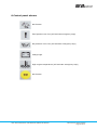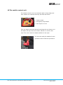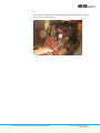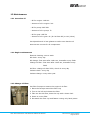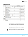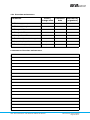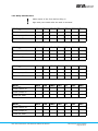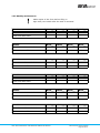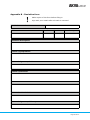
1
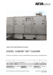
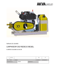
USER AND MAINTENANCE MANUAL
DIESEL CABINET NET CLEANER
D-Drive K-136-300-SD, D-Drive K-188-300-SD-JD and D-Drive K-240-280-SD-JS
A
10.10.14
Rev
Date
Document
no.:
Approved (ECO-0000591)
Issued
DC10000763
Documents
part no.:
10001146
User and maintenance manual Diesel Cabinet Net Cleaner
EBL
AT / IS
Issued by
Approved by
Project no.:
88075-01
Document no. DC10000763
Page 1 of 51
For a thorough introduction of Your AKVA product, we ask that
all users read this entire manual. If questions occur, contact us!
The information in this document is subject to change without
notice and should not be construed as a commitment by AKVA
group ASA.
AKVA group ASA assumes no responsibility for any errors
that may appear in this document.
In no event shall AKVA group ASA be liable for incidental or consequential damages arising from use of this document or of the
software and hardware described in this document.
We reserve all rights in this document and in the information
contained therein. Reproduction, use or disclosure to third
parties without express authority is strictly forbidden.
Additional copies of this document may be obtained from
AKVA group ASA at its current charge.
© 2014 AKVA group ASA (NO)
AKVA group ASA
User and maintenance manual Diesel Cabinet Net Cleaner
Document no. DC10000685
Page 2 of 51
Table of contents
1
Safety ......................................................................................................5
1.1
Safety symbols .......................................................................................... 5
1.2
General safety ........................................................................................... 6
1.3
Personnel safety ........................................................................................ 6
1.4
Equipment safety ....................................................................................... 7
1.5
Receiving new equipment and warranty ...................................................... 10
2
Introduction ..........................................................................................11
2.1
Contact information .................................................................................. 13
3
Information ...........................................................................................14
3.1
Model description ..................................................................................... 16
4
High pressure cleaner’s main components ............................................. 17
4.1
Specifications .......................................................................................... 18
4.2
Specifications Washing rigs ....................................................................... 18
5
Before use .............................................................................................19
5.1
General precautions ................................................................................. 19
5.2
Oil check ................................................................................................. 20
5.3
Coolant ................................................................................................... 22
5.4
Hoses...................................................................................................... 22
5.5
Suction hose ........................................................................................... 22
5.6
Safety/bypass valves ................................................................................ 23
5.7
Net cleaning frames ................................................................................. 24
6
Starting and stopping the machinery ..................................................... 25
6.1
Instructions.............................................................................................. 26
6.2
Treadle.................................................................................................... 27
7
Emergency stop and restart ...................................................................28
8
Control panel alarms .............................................................................29
9
Net cleaning frames ...............................................................................30
10
The mobile control unit ..........................................................................31
User and maintenance manual Diesel Cabinet Net Cleaner
Document no. DC10000763
Page 3 of 51
11
Cleaning and storage .............................................................................32
11.1
Cleaning after each use ............................................................................ 32
11.2
Cleaning instructions before storage ........................................................... 33
11.3
Cleaning the washing rig ........................................................................... 33
12
Maintenance ..........................................................................................35
12.1
Overview oil ............................................................................................ 35
12.2
Engine maintenance ................................................................................. 35
12.3
Change oil filter ....................................................................................... 35
12.4
Change diesel filter .................................................................................. 36
12.5
Ventilating the diesel system ..................................................................... 36
12.6
Gear maintenance .................................................................................... 36
12.7
Oil cooler maintenance ............................................................................. 37
12.8
Coarse strainer maintenance ..................................................................... 37
12.9
Pump maintenance ................................................................................... 37
12.10 Feed pump maintenance ........................................................................... 37
12.11 Changing zink anode ................................................................................ 38
12.12 Air filter maintenance ............................................................................... 38
12.13 Sea water filter maintenance ..................................................................... 39
12.14 Check coolant .......................................................................................... 39
12.15 Battery maintenance ................................................................................ 40
12.16 Net cleaning frame maintenance ................................................................ 41
13
Maintenance plans .................................................................................42
13.1
First time maintenance ............................................................................. 43
13.2
Daily maintenance ................................................................................... 44
13.3
Weekly maintenance ................................................................................ 45
13.4
Registration of maintenance ...................................................................... 46
Appendix A - Index ..........................................................................................47
Appendix B - Deviation form ............................................................................49
Appendix C - Notes ..........................................................................................50
User and maintenance manual Diesel Cabinet Net Cleaner
Document no. DC10000763
Page 4 of 51
1 Safety
Safety for the users of our equipment is top focus when AKVA
group ASA develop new products and product manuals.
We therefore strongly recommend that everyone that use the
equipment, all that perform any type of repairs, service or other
maintenance to the product, and all that work in areas where the
product is installed read this entire manual and at least this
safety chapter.
This recommendation is based on both personnel safety as well
as a desire to keep the products in order and avoid damages
risked if the safety instructions are not followed.
1.1 Safety symbols
The following safety symbols are used in this manual:
Information
Show caution, danger of damaging equipment and mild
injuries to personnel
Use ear protection
Warning, may cause injures to personnel
Dangerous situations may occur, danger of escaping
1.1.1 Other symbols used in this manual
Go to or see page or chapter for further instructions or more
information
User and maintenance manual Diesel Cabinet Net Cleaner
Document no. DC10000763
Page 5 of 51
The net cleaning system must not be operated, and no
work may be performed on the system before the entire
manual and especially the safety precautions described in
this chapter have been read and understood
1.2 General safety
Show general caution when using high pressure equipment. The
equipment generates strong forces and may cause severe
damage to both personnel and equipment if used incorrectly.
When using high pressure net cleaners, the “Regulations about
high pressure cleaning and more” (FOR 1992-02-13 nr 1263:
Forskrift om høytrykksspyling m.m.), has to be complied.
According to § 4 in these regulations, overstepping them is a
legal offence.
1.3 Personnel safety
All personnel must be trained in how to operate the equipment,
and also be instructed in all dangers that may occur by improper
use. (ref. § 6)
Employer is responsible for informing all personnel about all
safety precautions as well as explaining which of the operations
may cause personnel injuries. All personnel must be instructed
in all of the safety instructions, and it is employers responsibility
every employee understands these instructions. (ref. § 7)
Employer must instruct all personnel to use appropriate safety
equipment and garments when working with high pressure
systems. Always use antiskid footwear when walking around the
cage edge. (ref. § 9)
If the net cleaner operator can not see the pumping aggregate
directly, an assisting operator is required. The net cleaner
operator must be able to communicate with the assisting
operator, preferably visually. (ref. § 22)
User and maintenance manual Diesel Cabinet Net Cleaner
Document no. DC10000763
Page 6 of 51
Sealing leaks within piping- or hose fittings, must only be
performed on depressurized equipment. (ref. § 13)
Employer is responsible of marking all areas where high
pressure equipment is being used, as well as securing the
danger area properly. (ref. § 23)
When cleaning with manually operated high pressure equipment,
only devices with balanced reaction force must be used. Only
one diver may stay in the water where the high pressure washer
is being used. A diving assistant must control the pumping
aggregate, so that the process can be shut down immediately in
case of an emergency. (ref. § 26)
Under aged personnel (under 18 years of age) must not operate
the washer alone. (ref. Regulations about work performed by
children and youth, § 9)
1.4 Equipment safety
1.4.1 Storage
Do not store the equipment at too high temperatures because
of the risk of contagious Legionella bacterial growth within the
system. It is advised that the equipment is rinsed off with a
narrow beam of fresh water directed away from people after
storage.
Salt water drying inside the high pressure pump and
components surrounding the pump (suction pump, filters,
bypass valve, hoses or other salt water leading components)
must be avoided. When this happens, salt crystals are left inside
as the water vaporises, and they may cause damage to gaskets
and sealings, high abrasion and reduces the equipment’s
functions. Therefore, if the equipment is going to be stored for
more than one week, it is recommended that the entire system
is flushed through with fresh water before placing in storage.
User and maintenance manual Diesel Cabinet Net Cleaner
Document no. DC10000763
Page 7 of 51
For over winter storage, avoid temperatures below the freezing
point (100⁰C and 32⁰F). It is also recommended to flush the
system with a water containing anti-freeze fluid, to prevent the
inside water to freeze and possibly destroy the equipment if
exposed to freezing-temperatures. The antifreeze solution will
also function as lubricant for the system and its internal
components.
1.4.2 General treatment of the equipment
All mechanical and electronic equipment used in the aquaculture
industry must be maintained properly in order to function over
time and according to expectations, especially in periods when
they are being used the most. High pressure washers work in
demanding environments with high pressures, large amounts of
water and an aggressive corrosive salt water environment.
Because of this, following the maintenance instructions are
highly required.
Materials that do not require much maintenance are chosen for
most of the critical components. Most of the exterior
components, however, would be too expensive to produce of
corrosion resistant materials. Therefore, rinsing the equipment
with fresh water after every use is highly recommended to avoid
surface corrosion.
All the movable parts, such as hinges, locks, gas regulators,
wheels and such, must be lubricated after rinsing. If scratches or
other damages appear in any enameled surfaces, these must be
sealed with wax or lubricant immediately in order to prevent
further corrosion.
Before using the equipment, always make sure it stands
steadily, and if necessary, is securely attached to the foundation
to prevent it from slipping and damaging its surrounding
equipment or personnel.
User and maintenance manual Diesel Cabinet Net Cleaner
Document no. DC10000763
Page 8 of 51
If the equipment is going to be moved from one site to another,
it is required by law to disinfect the equipment to avoid spread of
contagious diseases. Some disinfectants may be aggressive to
some metals, o-rings, sealings and other internal components.
Therefore, rinse the equipment after use of disinfectants, both
inside and outside, with fresh water.
1.4.3 Inspection before use
High pressure water represents massive forces, and therefore it
is important that critical components are inspected and tested
frequently.
Bypass/safety valves are installed at all high pressure equipment
to ensure that no higher pressure than the maximal pressure
endured by the various components occurs. The safety valve is
set to open up for water flow in case the water pressure inside
the system exceeds the predetermined level. If any of these
valves are out of order when the system runs, this can cause
severe damages to the equipment and injure personnel.
(ref. § 30)
The safety valve is set to a pressure value the equipment
endures while in use. Never change this value to a higher
pressure. (ref. § 14)
All hoses used in the construction, must be able to endure the
working pressure of the equipment. Read the mark on all hoses
to make sure they can bear the pressure before using them. All
hoses must be inspected for external damages. If the hose is
damaged, it must be replaced or repaired before use.
The information regarding safety in this manual must not
be construed as a warranty by AKVA group ASA that the
high pressure washer will not cause injury or damage
even if all safety instructions have been complied with
User and maintenance manual Diesel Cabinet Net Cleaner
Document no. DC10000763
Page 9 of 51
1.5 Receiving new equipment and warranty
Make sure that all parts are delivered according to the service
note.
If the order should not be complete, or any defects are discovered, contact AKVA immediately, contact information is found in
chapter 2.1.
AKVA group ASA offers a 1 year warranty, covering production
defects. This warranty is efficient after date of shipment to original customer.
User and maintenance manual Diesel Cabinet Net Cleaner
Document no. DC10000763
Page 10 of 51
2 Introduction
This user manual is part of the equipment delivered with
Akvasmart Idema Net Cleaner. Keep all belonging
manuals as long as the net washer is in use, and make
sure that all changes to any of the equipment are being
noted in the manual.
Thank you for choosing AKVA group ASA as supplier for your
high pressure net cleaning system. Do not hesitate contacting us
if you need more information regarding use or maintenance for
your product.
With four house brands, AKVA group ASA is a world leading
supplier of technical aquaculture equipment. Since 1980 we
have developed and produced fish farming equipment, both for
cages at sea and for land based hatcheries. AKVA represents an
industrial standard, which is presumed to be the turn key to the
future. Research, project management, fast deliveries and
customer follow-up have been in focus to ensure that we deliver
the best possible and most cost efficient equipment, and thus
contributing to preserve a sustainable aquaculture and a positive
development within the aquaculture industry.
We have a wide variety of products, for example: plastic and
steel cages, high pressure washers, net washers, boats, feed
barges, feeding systems, cameras, sensor systems, under water
lighting, software for fish farming and recycling systems.
We practice continuous product development to improve the
equipment’s safety, functions, manner of operation and working
reliability. All our net cleaning products are developed and
produced according to the following standards and procedures:
User and maintenance manual Diesel Cabinet Net Cleaner
Document no. DC10000763
Page 11 of 51
- ISO-EN 12100 Part 1&2: Safety of machinery
- EC-Directive 98/37/EC: Machinery Directive
- EC-Directive 97/23/EC: Pressure Equipment
All of our equipment is pre-installed, tested and delivered from
our own production department or from approved collaborators.
Our production staff consists of people with great expertise and
enthusiasm to produce the best possible products for you.
Having our own production site gives our customers excellent
service in case something should go wrong, or if assistance is
required. AKVA hold most of the parts for our products in stock,
and our service staff is available on the telephone or on location
in order to assist you if necessary. Safety, both for the user and
for the equipment is our main focus when developing products.
This entire manual, and especially the safety chapter
must be read and understood before commencing any
work on the equipment
Before any work - including maintenance and repairs, is done
with or on the Akvasmart Idema Net Cleaner, we recommend
that all users are properly trained by AKVA group ASA. Users
need to get to know this manual and its contents, and perform
procedures and maintenance as described here to ensure
reliable operations and a long lasting product. This manual
answers most day to day questions and gives a thorough
description of how to use and maintain the Akvasmart Idema
Net Cleaner.
User and maintenance manual Diesel Cabinet Net Cleaner
Document no. DC10000763
Page 12 of 51
2.1 Contact information
AKVA group ASA - Bryne (Head office)
Nordlysveien 4
PO. Box 271
4340 Bryne
Norway
tel. +47 - 51 77 85 00
fax. +47 - 51 77 85 01
Support Hardware and AKVAconnect
tel. + 47 - 51 77 85 03
[email protected]
Support Fishtalk
tel. +47 - 73 84 28 20
[email protected]
User and maintenance manual Diesel Cabinet Net Cleaner
Document no. DC10000763
Page 13 of 51
3 Information
Idema Net Cleaners were launched in 1987, and are today
renowned for quality, high performance and their ease of use.
The first Net Cleaners had single 30cm diameter cleaning discs,
operated from the cage edge using a shaft. Underwater pressure
washing of cages where fish reside, has become even more
common as the requirement to environmentally friendly aquaculture in larger cages provides the best scale of economics.
With this in mind, we have developed and improved the
Akvasmart Idema Net Cleaners, and can now present the best
range of net cleaners and high pressure pumps ever. This combination offers the most efficient cleaning system suited for all
types and sizes of cages.
In net cleaning, filtered high pressure sea water is used to
remove marine fouling on the nets. Akvasmart Idema Net
Cleaners use rotating cleaning discs mounted on support frames
in various shapes and combinations. We use rugged, tailor-made
high pressure pumps to run the cleaning discs.
The cleaning process starts with submerging the frame in the
inside of the net, using high pressure sea water. Idema cleaning
systems do not use any chemicals or scrubbing action, making
them environmentally friendly and ensuring minimal wear on the
net.
The large net cleaners can be operated automatically by two
persons using a crane, winch, cap stand or as a integrated
option on a ROV (Remotely Operated Vehicle). The smallest net
cleaners can easily be operated from the cage edge by a single
person.
Larger net cleaning frames can be delivered with cameras
and recording systems that give full overview over the cleaning
process, and makes it possible to inspect the net as it is being
cleaned.
User and maintenance manual Diesel Cabinet Net Cleaner
Document no. DC10000763
Page 14 of 51
Gasoline, diesel or hydraulic driven net cleaners
AKVA group offers a rugged series of high pressure washers for
seawater, suited for various system solutions and cage sizes.
The gasoline net cleaners are light-weight and perfect as
portable units.
The diesel net cleaners are almost maintenance free, use less
fuel than the gasoline models and are well suited for large,
powerful, permanent installations.
The hydraulic net cleaners are small, compact and almost
maintenance free, perfect for below deck installations in
workboats.
Net cleaning frames
The Idema Heavy Duty Cleaning
discs are equipped with stainless
steel frames. The discs have a
rotation speed from 750-1500 rpm.
User and maintenance manual Diesel Cabinet Net Cleaner
Document no. DC10000763
Page 15 of 51
3.1 Model description
All high pressure net cleaners delivered by AKVA group have a
uniform model description. The description contains information
about capacity, structure and function. Example:
1) K = Cold water, V = Hot water
2) Liter water per minute
3) Water pressure (bar)
4) Water supply: S = Integrated suction pump
X = Without suction pump
5) Engine type: H = Hydraulic
B = Gasoline
E = Electro
D = Diesel
6) Engine fabrication: CO = Comer
VA = Vanguard
HO = Honda
HZ = Hatz
IV = Iveco
JD = John Deere
SU = Sunfarb
7) Volume/effect: B and D - effect in Hp
E - effect in kW
H - volume in ccm/rev
User and maintenance manual Diesel Cabinet Net Cleaner
Document no. DC10000763
Page 16 of 51
4 High pressure cleaner’s main components
The cabinet front:
User and maintenance manual Diesel Cabinet Net Cleaner
The cabinet backside:
Document no. DC10000763
Page 17 of 51
4.1 Specifications
Net cleaner
Engine
Gear
Pump
K-136-300-SD
JD 6068 TF 258
ZF 301 C
MWN 32
K-188-300-SD
JD 6068 TF 258
ZF 301 C
LKN40 A 1750rpm
K-240-280-SD
JD 6068 HF 158 inter cooler 188hp
ZF 301 C
LKN 45 1750rpm
4.2 Specifications Washing rigs
Net cleaner
Washing rig
K-136-300-SD
Quad, Quint
K-188-300-SD
Quint, Hep
K-240-280-SD
Quint, Hep
User and maintenance manual Diesel Cabinet Net Cleaner
Document no. DC10000763
Page 18 of 51
5 Before use
5.1 General precautions
Show great caution when using any high pressure equipment.
These systems generate severe forces and may cause damages
to personnel and other equipment if used incorrectly. Regular
control and maintenance is required to ensure safest possible
use and as long lifetime as possible.
Reading every safety, user and maintenance instructions before
using the equipment will reduce risks of personnel injuries and
damages to the net cleaner and other equipment.
Bypass valves should open for water flow when the pressure
inside the system exceeds the predetermined level. If this is not
in order, the high pressure may cause serious consequences for
both equipment and personnel.
High pressure water represents severe forces. Therefore,
it is important that critical components are inspected and
tested regularly
All users must read this entire manual before using it to
make sure that all tasks are performed according to the
instructions
The predetermined level of pressure in bypass valves
must never be changed
Before every use, oil level in motor, gear and pump must
be controlled according to the instructions in this chapter
User and maintenance manual Diesel Cabinet Net Cleaner
Document no. DC10000763
Page 19 of 51
5.2 Oil check
The motor and the gear box have dipsticks for checking oil.
Motor dipstick is found on the back side of the cabinet, and the
gear box dipstick is found in the front. Gear oil is filled into the
same opening as the dipstick is put, and motor oil is filled into an
opening in the front of the cabinet.
Read the oil level from the dipsticks.
Add oil if the oil level reaches the “Add” area, and
drain oil if it reaches the “Overfill” area.
The pump has an oil level window (oil see glass) placed on the
side facing the gear, and a refill hole on top.
Gear: use same opening for check and refill in the front
Motor: check in the back, fill in the front of the cabinet
Pump: check in the front, fill in the top of the pump
See overview in the next page for overview of check and refill of
oils for motor, gear and pump
User and maintenance manual Diesel Cabinet Net Cleaner
Document no. DC10000763
Page 20 of 51
Net cleaner front side:
Net cleaner back side:
For further information on engines, gears and pumps, see the
respective manuals.
User and maintenance manual Diesel Cabinet Net Cleaner
Document no. DC10000763
Page 21 of 51
5.3 Coolant
Check the coolant level on top of the radiator.
Open the lid to check the level. Refill in the same opening.
5.4 Hoses
All hoses used with this high pressure cleaner must be
constructed in order to bear the working pressure of the
equipment. Make sure the hose you are using can bear this
pressure, by reading the labelling on the outside of the hose.
Hoses must be checked for tears and other damages. In case of
damage, repair or replace the hose before use.
5.5 Suction hose
Make sure that the suction hose is well attached to
the feed pump.
It is important that the entire suction filter is below
water during the running of the net cleaner.
User and maintenance manual Diesel Cabinet Net Cleaner
Document no. DC10000763
Page 22 of 51
5.6 Safety/bypass valves
The predetermined level of pressure in the bypass valves
must never be changed
Safety/bypass valves are installed in all high pressure
equipment to ensure that the pressure inside the system never
exceeds the component’s maximum pressure tolerances.
The bypass valves are set to open for water flow when the water
pressure inside the system exceeds the predetermined level.
If one valve is out of order, the high pressure that builds up
inside the system may cause serious consequences for both
equipment and personnel.
If water appears in the hoses connected to a bypass valve,
something is wrong:
- Something may be wrong with the bypass valve itself. In that
case, the valve must be overhauled or changed before use
- The pressure can be higher than the predetermined pressure.
The most common cause of this is that one or more nozzles in
the net cleaner are clogged. Check these and rinse them if
they are clogged
- Check all hoses, including the ones on the net cleaning frames
for bends, and flatten these
- Contact AKVA service personnel if the problem can not be
solved according to these instructions. Contact information is
found in chapter 2.1.
User and maintenance manual Diesel Cabinet Net Cleaner
Document no. DC10000763
Page 23 of 51
5.7 Net cleaning frames
Check the hoses on the net cleaning frame for bends, these
should be flattened.
Check hoses for tears and other destructions. Repair or replaced
damaged hoses before use.
Check all hose couplings and tighten if necessary.
Run the system with feed pressure to check the conditions of all
the nozzles.
User and maintenance manual Diesel Cabinet Net Cleaner
Document no. DC10000763
Page 24 of 51
6 Starting and stopping the machinery
All users must read this entire manual before using it to
make sure that all tasks are performed according to the
instructions
After going through, and preparing all of the inspection
instructions, you can safely start the system like this:
Control panel:
User and maintenance manual Diesel Cabinet Net Cleaner
Document no. DC10000763
Page 25 of 51
6.1 Instructions
1 Set the main switch (yellow ring) to “ON”
2 Press and hold the red button in the control panel
3 Turn the key
4 Press the green start button until the machinery starts
(this normally takes about 2 seconds)
5 Release the red alarm avoider button
6 Open the cabinet door and engage the pump by moving the
treadle forwards until you feel a slight resistance (see
illustration in the next page). Leave the treadle here for about
ten seconds, so that the pump can build up pressure before
increasing the speed
7 After 10 seconds, the power might be set to necessary
working pressure
8 To stop, turn the treadle back to the start position, and leave
the engine running idle to cool down the system. A immediate
stop may cause destructions to the turbo and bearings. Leave
the engine running for 3-5 minutes to prevent these potential
destructions
9 Turn the key back to stop the system.
User and maintenance manual Diesel Cabinet Net Cleaner
Document no. DC10000763
Page 26 of 51
6.2 The treadle
a. Start up position
b. Leave the treadle in this position for about 10 seconds to build
pressure
c. Push the treadle forward to increase motor power
User and maintenance manual Diesel Cabinet Net Cleaner
Document no. DC10000763
Page 27 of 51
7 Emergency stop and restart
In case of emergency, press the emergency stop button
immediately.
Make sure that everything is ok before restarting the system.
The emergency stop button has to be released before restarting.
Turn the button according to the instruction arrow, and the
button will be released out to starting position again.
Before resetting after an emergency stop situation,
establish the reason for the stop and rectify the fault
User and maintenance manual Diesel Cabinet Net Cleaner
Document no. DC10000763
Page 28 of 51
8 Control panel alarms
No function
Feed pressure too low (will activate emergency stop)
Oil pressure is too low (will activate emergency stop)
Charge light
High engine temperature (will activate emergency stop)
No function
User and maintenance manual Diesel Cabinet Net Cleaner
Document no. DC10000763
Page 29 of 51
9 Net cleaning frames
Safety equipments such as anti skid footwear and floating
garments is mandatory when working on the cage edge
The rope for lowering and lifting the net cleaning frame is best
connected with a safety hook to prevent wearing and tearing on
the rope and prevents it from breaking.
The cleaning process is most efficient when the cleaning frame is
being pulled upwards. When going down in the water, the frame
will not sink controlled and will therefore not be cleaning very
efficiently. So, whether using crane or manual labor when
cleaning nets with high pressure cleaners, lower the frame as
controlled as possible to the bottom of the net, avoid disturbing
the fish. Then raise it slowly and controlled to achieve best
possible result.
The cleaning frame must always be held under water when the
machinery is running. For testing the nozzles, however it can be
run above water, but only using feed pressure.
User and maintenance manual Diesel Cabinet Net Cleaner
Document no. DC10000763
Page 30 of 51
10 The mobile control unit
The mobile control unit is an extension part to large high pressure cabinet net cleaners that may be used with winch.
1 - Power switch
2 - Emergency stop button
3 - Roll ropes in or out
This is a simple unit that controls how deep the net cleaner is in
the water. On top of the net cleaner cabinet is a reel for this
rope. The unit is used to release and haul in the rope.
The unit can easily be attached to the
operator’s belt to ease the procedure.
User and maintenance manual Diesel Cabinet Net Cleaner
Document no. DC10000763
Page 31 of 51
11 Cleaning and storage
Regular service and well performed maintenance are important
factors for keeping functions running as they should, and for the
product to operate according to expectations.
By following cleaning and maintenance instructions, the net
cleaner will always be ready for use, and service costs will be
minimized.
11.1 Cleaning after each use
- Keep the machinery clean, dry and in order
- Wash away any spills of oil immediately
- Do not use high pressure washers to clean this equipment, this
can cause water intruding into the engine, pump, gear and
electronics, and ruining these components
- Use a mild detergent, do not use strong degreasers
- The entire machine is coated with protection wax to reduce
corrosion. After cleaning, always apply a new layer of wax on
all surfaces. Apply the wax when the machinery is still warm,
this makes it stick longer and better.
Avoid letting salt water dry off inside the system. Rinse through
with fresh water after use to prevent corrosion and other
damages caused by salt crystals on metal, rubber and other
materials.
Rinse through with fresh water if the net cleaner is going to be
stored for one week or more.
Also, rinsing the outside with fresh water regularly prevents
corrosion in the surfaces. All moving parts, such as hinges,
wheels, locks, gas regulators must be lubricated after each fresh
water rinse.
User and maintenance manual Diesel Cabinet Net Cleaner
Document no. DC10000763
Page 32 of 51
Check all enamel covered surfaces for scratches, and fill these
with lubricant or wax to avoid further corrosion.
If the equipment is disinfected before being moved to a different
location, it has to be rinsed off with fresh water, and lubricant or
wax added as mentioned above.
11.2 Cleaning instructions before storage
1 Always run fresh water through the entire system after use
and when the net cleaner is going to be stored for more than
one week
2 Mix 80% water and 20% antifreeze solution and run this
through to conserve the system and to lubricate the sealings
and to reduce the danger of frost damages in case of storing
in temperatures below 0°C.
For storing in colder environments, increase the amount of
antifreeze solution. See instructions on the solution bottle
3 If the system might be exposed to frost, it is important that
the amount of water inside is as low as possible, so run the
machinery without water intake until the water is drained out
(no longer than 10 seconds!)
4 Empty pressure hoses and coil them up carefully.
11.3 Cleaning the washing rig
Do not disconnect the net cleaner from the system before is has
been flushed through with fresh water.
All hoses and nozzles need rinsing too.
Remove filth and sprout from the discs, in front and especially
between discs and the hubs.
Clean the ejectors intakes.
User and maintenance manual Diesel Cabinet Net Cleaner
Document no. DC10000763
Page 33 of 51
Warning! If the net cleaner is not maintained and cleaned properly, this is what it
may end up like after some time:
User and maintenance manual Diesel Cabinet Net Cleaner
Document no. DC10000763
Page 34 of 51
of 46
12 Maintenance
12.1 Overview oil
- Oil for engine: 10W-40
- Amount of oil in engine: 20L
- Oil for pump: SAE 220
- Amount of oil in pump: 7L
- Oil for gear: SAE 30
- Amount of oil in gear: 9L (K-136-300-SD) or 14L (other)
Use dipsticks and oil see glasses to make sure that the oil
amounts are correct for all components.
12.2 Engine maintenance
External cleaning: once a week
Oil check: every day
Oil change: First time after 100h use, thereafter every 500h
Change oil filter: First time after 100h use, thereafter every
500h
Air filter: change oil after 250h, check oil every day
Coolant check: every day
Coolant change: every other year
12.3 Change oil filter
Use filter forceps to remove the engine’s oil filter.
1 Place the forceps around the filter cup
2 Turn to the left and release the filter
3 Take out the old filter, clean the cup with a clean cloth
4 Insert in a new filter
5 Re-attach the filter cup and fasten it using only hand power.
User and maintenance manual Diesel Cabinet Net Cleaner
Document no. DC10000763
Page 35 of 51
of 46
12.4 Change diesel filter
No tools are necessary for changing the diesel filter.
1 Open the filter cup
2 Check filter for impurities
3 Clean if possible or change filter if it is too filthy
4 Place the filter cup back on the machine.
12.5 Ventilating the diesel system
When air appears inside the diesel system, it needs to be
ventilated out of the system.
Air can appear inside the system after:
- running out of diesel
- changing diesel filter
- any work is done with the system
The ventilation handle is placed on the right side of the diesel
filter. Push the handle upwards several times, until you can feel a
smooth resistance.
12.6 Gear maintenance
Cleaning: once a week
Oil level: once a day
Oil change, sieve cleaning: first time after 50h use, thereafter
every 500h use or once a year
Oil cooler, cleaning and if necessary, change of zink anode:
- every six months
User and maintenance manual Diesel Cabinet Net Cleaner
Document no. DC10000763
Page 36 of 51
of 46
12.7 Oil cooler maintenance
1 Remove the end lid
2 Take out the internal parts and clean them
3 Stake the insides, clean and blow away any contaminations
Replace the internal parts
4 Replace the lid.
12.8 Coarse strainer maintenance
When gear oil is changed, the coarse strainer must be checked.
1 Release the plug
2 Remove the filter and clean or replace it
3 The two screws must be fastened with 18 Nm torque when
reattaching the filter.
12.9 Pump maintenance
Cleaning: once a week
Oil check: every day
Oil change: first time after 50h use, thereafter every 500h
Inspection, function test: when required
Vents: when required
Pressure gaskets: when required
Pistons: when required
12.10 Feed pump maintenance
Impeller inspection: when required, but at least once a year
Impeller change: when required
Change ball bearings and gaskets: when required
Remove the cover and look inside to control the impeller visually
Repair or change impeller if necessary.
User and maintenance manual Diesel Cabinet Net Cleaner
Document no. DC10000763
Page 37 of 51
of 46
12.11 Changing zink anode
The zink anode is placed inside the nut marked with a yellow ring
in the illustration to the left. This anode needs to be replaced
every sixth months.
1 Release the nut
2 Remove the anode
3 Place a new anode in
4 Attach the nut.
12.12 Air filter maintenance
The air filter has an indicator placed on top of the engine, and
when this turns red, it needs to be replaced.
1 Release the cover by loosening the clamps (marked with
yellow rings in the left image below)
2 Remove the filter
3 Check for filth and replace filter if it is too clogged for
cleaning.
User and maintenance manual Diesel Cabinet Net Cleaner
Document no. DC10000763
Page 38 of 51
of 46
12.13 Sea water filter maintenance
Dual-pumped net cleaners have two sea water filters. These are
placed above the pump in the cabinet. The filter must be
checked every 100h.
1 Loosen the clamp around the cover and remove the cover
2 Unscrew the wing nuts
3 Remove the cover and take the filter out for inspection
4 Clean or replace the filters when required.
12.14 Check coolant
The coolant must be changed every other year.
1 Drain all of the coolant by opening the draining valve placed in
the bottom of the radiator
2 Refill with fresh coolant and remember to check the level in
the opening on top.
User and maintenance manual Diesel Cabinet Net Cleaner
Document no. DC10000763
Page 39 of 51
of 46
12.15 Battery maintenance
Battery level and poles checked every six months. When the
poles become dirty, quick discharging of the battery may
become a problem because the power may leak. Therefore,
clean battery poles are important for optimal charge.
Before cleaning, the poles must be removed from the battery.
Use protection gloves and goggles to avoid being hurt by
the very corrosive battery acid.
Use a steel brush to clean the poles.
Brush and clean the poles until they are shiny and clean.
Blow off any scrapings.
User and maintenance manual Diesel Cabinet Net Cleaner
Document no. DC10000763
Page 40 of 51
of 46
12.16 Net cleaning frame maintenance
Change ball-bearing when required. To test if bearings must be
changed, spin the discs manually one by one and listen for
rumbling sounds. When the bearings are ok, there should be no
sounds, and if any rumbling sounds appear during this test, the
bearings in the tested disc must be changed.
Run the system with feed pressure to check the condition of the
nozzles on the net cleaner.
Make sure to check all nozzles, and clean them if necessary.
Hoses and hose couplings must be checked every six months.
User and maintenance manual Diesel Cabinet Net Cleaner
Document no. DC10000763
Page 41 of 51
of 46
13 Maintenance plans
Fill in week number in the daily maintenance form on the next
page, and fill inn month name in the weekly maintenance form.
This is important to maintain regular and correct maintenance.
When a task is performed, sign the correct box.
Make copies of the forms before filling them in, and keep the
copies in the maintenance folder.
Mark the last copy with a post-it or something similar to make
sure that you never run out of copies!
User and maintenance manual Diesel Cabinet Net Cleaner
Document no. DC10000763
Page 42 of 51
of 46
13.1 First time maintenance
Parameter
Check/
Execution
Executed by
change after
date
(signature)
1. Oil change, pump
25h
2. Oil change, engine
100h
3. Change oil filter
100h
4. Change air filter
250h
5. Change diesel filter
500h
6. Check level/clean battery poles
6 months
7. Inspection, impeller
1 year
8. Function test, pump
1 year
Comments to first time maintenance
User and maintenance manual Diesel Cabinet Net Cleaner
Document no. DC10000763
Page 43 of 51
of 46
13.2 Daily maintenance
Make copies of this form before filling in
Sign with your initials after the task is executed
Week__
Mon
Tue
Wed
Thu
Fri
Sat
Sun
Mon
Tue
Wed
Thu
Fri
Sat
Sun
Mon
Tue
Wed
Thu
Fri
Sat
Sun
Mon
Tue
Wed
Thu
Fri
Sat
Sun
Mon
Tue
Wed
Thu
Fri
Sat
Sun
Check motor oil
Check pump oil
Check air filter
Week__
Check motor oil
Check pump oil
Check air filter
Week__
Check motor oil
Check pump oil
Check air filter
Week__
Check motor oil
Check pump oil
Check air filter
Week__
Check motor oil
Check pump oil
Check air filter
User and maintenance manual Diesel Cabinet Net Cleaner
Document no. DC10000763
Page 44 of 51
of 46
13.3 Weekly maintenance
Make copies of this form before filling in
Sign with your initials after the task is executed
Month:
Week__
Week__
Week__
Week__
Week__
Week__
Week__
Week__
Week__
Week__
Week__
Week__
Week__
Week__
Week__
Week__
Week__
Week__
Week__
Week__
Week__
Week__
Week__
Week__
Clean the machine with fresh water
Clean sea water filter
Month:
Clean the machine with fresh water
Clean sea water filter
Month:
Clean the machine with fresh water
Clean sea water filter
Month:
Clean the machine with fresh water
Clean sea water filter
Month:
Clean the machine with fresh water
Clean sea water filter
Month:
Clean the machine with fresh water
Clean sea water filter
User and maintenance manual Diesel Cabinet Net Cleaner
Document no. DC10000763
Page 45 of 51
of 46
13.4 Registration of maintenance
Make copies of this form before filling in
Sign with your initials after the task is executed
Date
Parameter description
User and maintenance manual Diesel Cabinet Net Cleaner
Operating
Next
hours
change
Signature
Document no. DC10000763
Page 46 of 51
Appendix A - Index
A
G
after use 9, 32, 33
gaskets 7, 37
air filter 35, 38
gear 18-21, 32, 35-37
antifreeze fluid 8, 33
H
B
high pressure pump 7, 14
ball bearings 33, 34
hose 7-9, 22-24, 33, 41
battery 17, 40
bypass valve 7, 9, 19, 23
I
impeller 37
C
indicator 38
charge 29, 40
inspect 14, 19, 25, 37, 39
cleaning 6, 7, 14-19, 21-24, 30-41
instruction 5,6,8,9,19,23,25,26,28,32,33
coarse strainer 37
coolant 22, 35, 39
critical components 8, 9, 19
D
diesel filter 36
dipstick 20, 35
discs 33, 41
disinfection 9, 33
diver 7
E
ejectors intakes 33
emergency stop 28, 29, 31
F
feed pressure 24, 29, 30, 41
feed pump 22, 37
filter forceps 35
fresh water 7-9, 32, 33
L
Legionella 7
lubricant 8, 32, 33
M
maintenance plan 42
N
nozzles 23, 24, 30, 33, 41
P
pistons 37
poles 40
predetermined pressure 9, 19, 23
pressure gaskets 37
pressure hose 33
R
radiator 22, 39
frost 33
User and maintenance manual Diesel Cabinet Net Cleaner
Document no. DC10000763
Page 47 of 51
S
V
safety hook 30
ventilation handle 36
safety equipment 6, 30
vents 37
sea water filter 39
sealings 7, 9, 33
sieve 36
suction filter 22
suction hose 22
W
working pressure 9, 22, 26
Z
zink anode 36, 38
T
test 9, 12, 19, 30, 37, 41
treadle 26, 27
User and maintenance manual Diesel Cabinet Net Cleaner
Document no. DC10000763
Page 48 of 51
Appendix B - Deviation form
Make copies of this form before filling in
Sign with your initials after the task is executed
Deviation control no.:
Unit:
Producer:
Prod.no.:
Purchase year:
Deviation description:
Follow up proposition:
Date and signature, declarer:
Follow up directed:
Status:
New action for deviation no.:
Date and signature, follow up:
User and maintenance manual Diesel Cabinet Net Cleaner
Document no. DC10000763
Page 49 of 51
of 51
Appendix C - Notes
User and maintenance manual Diesel Cabinet Net Cleaner
Document no. DC10000763
Page 50 of 51
of 51
User and maintenance manual Diesel Cabinet Net Cleaner
Document no. DC10000763
Page 51 of 51