1
MultiSight™ User Manual
Setup—Quick Guide
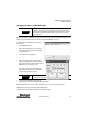
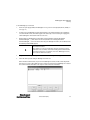
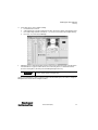
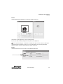
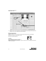
Click on the “Stop” button to stop live image.
Change the trigger mode to “Continuous.”
This makes it easier to check good and bad parts.
Click on the “Teach” and select “Teach from PC image” button to
teach the pattern. Click on the “Stop” button after a few
seconds.
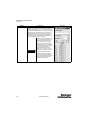
Notice the taught pattern display in the “Pattern Section.”
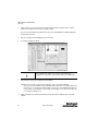
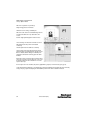
Select “Live Images” check box in the Select Detector section.
Click the “Run” button. The pattern is now evaluated
continuously.
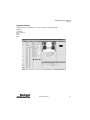
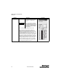
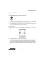
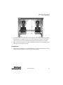
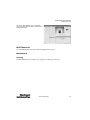
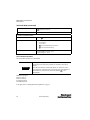
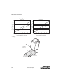
The desired pattern is detected with 100% conformity.
The green outline on the image indicates where the taught
pattern is found. The green bar graph (in the “Results” & “Select
Detector” windows) indicates the degree of similarity to the
taught pattern. The black line on the bar graph is the current
threshold.
Further objects can be set using the same procedure described
above. Select a new detector in “Select Detector” section, select
the desired parameters in “Detector Parameter” section and
repeat the above steps.
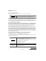
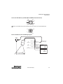
If several objects or detectors are defined, they can be logically linked or grouped (see Select Detector/Logic on page 26).
Set the threshold value (required degree of conformity of the pattern detected with the pattern taught). This can be achieved by
testing a variety of good parts and adjusting the “Threshold Min” parameter in the “Detector Parameters” window.
54
10000000877(02)