1
MultiSight™ User Manual
Start-up
Command
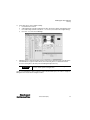
Recorder Images
Description
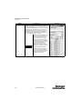
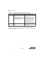
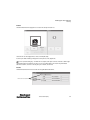
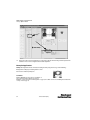
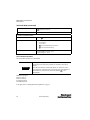
Transfers the images saved on the MultiSight to the computer.
The MultiSight can save up to 30 images on its local memory. To save images, the Recorder
parameter in the Select Detector window must be turned on (see page 27). Based on the
setting of that parameter, the MultiSight can save either the last 30 images or the last 30
images of inspections that resulted in an output of FAIL.
When the images are transferred to the computer, they are deleted from the MultiSight
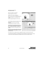
memory. In order to keep the image, it must be saved to the computer using the Save button
on the Saved Pics pop-up window that opens when the images are transferred.
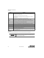
It is possible to save either the current image or all the images by using the Save or Save All
buttons. The images are stored as bitmap files (.bmp).
Images are saved in dynamic memory and are, therefore, lost if the sensor loses power or is
turned off.
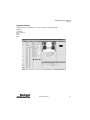
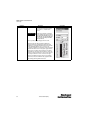
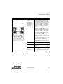
Select Detector
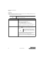
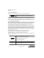
The MultiSight can be configured with up to ten ( E 32) virtual detectors (i.e. inspection of ten ( E 32) different characteristics).
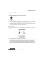
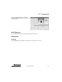
In order to configure one of the ten ( E 32) detectors, select the appropriate numbered radio button in the Select Detector
window. The current configuration of that detector appears and can be edited in the Detector Parameters section. (If that detector
on the MultiSight has not been previously configured, the default values appear.) Parameters that are changed in the software are
immediately changed on the MultiSight in dynamic memory. In order to permanently save changes in Flash memory on the
MultiSight, click the Write to Flash button in commands window..
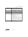
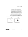
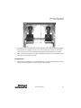
When the sensor is in run mode, each detector is independently evaluated. The results of these evaluations are indicated to the right
of the radio buttons for each detector. The small grey dots change color to represent the results of the individual detector evaluation,
with green indicating PASS and red indicating FAIL. The first dot is for inspection (pass/fail) OUT1 (LED Q1) and the second dot is for
position OUT2 (LED Q2). While in run mode, a green (or blue) line on the bar graph indicates the degree of similarity to the pattern or
contour the sensor has been taught for that detector. When using contrast or brightness detector types, the bar graph indicates the
level of contrast or brightness. The black line on the bar graph represents the threshold (configured in the “Detector Parameters” on
page 34).
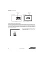
Detectors can be logically linked together. For example, the sensor can be set up to inspect multiple components on a product. Each
component is inspected by a single detector. The evaluation result of each detector is then logically combined with the evaluation
results of all the other detectors, resulting in a single output (OUT1/LED Q1). If the AND (All) logic is selected, all selected detectors
must pass evaluation for the pass/fail output OUT1 to give a PASS output. (If any one detector fails its evaluation output OUT1 gives
a FAIL output.) If the OR (Search) logic is selected, OUT1 gives a PASS output if any one of the detectors passes its evaluation. See the
parameter descriptions below for an explanation of how to logically link detectors.
Detectors can also be grouped. The grouping of detectors makes it possible to check several characteristics on different parts without
reconnecting the software during part changes. For example, during the first production shift of the day Part A is inspected for
several characteristics, then during the second production shift Part B is inspected for different characteristics. The sensor can be
changed via the Control Input on the PWR and I/O connector from Part A to Part B without having to reconnect to the software via
the Ethernet port. See “Use of Control Input IN2” section on page 58.
26
10000000877(02)