1
INSTALLATION AND OPERATING INSTRUCTIONS
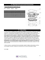
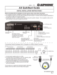
KESSEL - Aqualift® F Lifting Station (400 Volt)
For all wastewaters (with / without sewage)
For installation in frost free areas
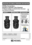
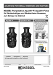
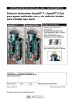
Aqualift® F Lifting Station (400 V)
Product Advantages
Easy connection to preformed inlets
Connection areas for
additional inlets
Fully automated operation
Maintenance friendly
Certification No. Z-53.2-424
The installation and service of this unit should be carried
out by a licensed professional servicer
Company - Telephone No.
Edition 01/2006-HG
(Subject to technical amendments)
ID number 010-606
Declaration of EC-Conformity
according to machine guide line 89/392/EWG of 14.06.1989 and modification guidelines 91/368/EWG of
20.06.1991, 93/44/EWG of 19.07.1993 and 93/68/EWG of 22.07.1993, low-voltage guideline 73/23/EWG and
guideline regarding electromagnetic compatibility 93/97/EWG of 29.10.1993
The producer
KESSEL GmbH, D-85101 Lenting
confirms that the product
KESSEL Aqualift® F lifting station
for free standing installation
was developed and produced
in accordance with the following norms:
EN 292
VDE 31001
VDE 0113
EN 55082-2
EN 55011
EN 55014
EN 60335
Lenting, 01.01.1999
2
Table of Contents
1
Safety Precautions
2.
General
3.
4.
Technical Data
Installation
5. Electrical Connections
6. Commissioning
page 5
2.1 Application / Installation
page 7
2.2 Aqualift® F description
page 7
3.1 Dimensions
page 8
3.2 Pump
page 10
3.3 Operating volume
page 11
3.4 Electrical Control Unit
page 11
4.1 Installation location tips
page 12
4.2 Pipe connections
page 13
4.3 Setting the pressure switch
page 16
5.1 General information
page 17
5.2 Control unit installation / mounting
page 17
5.3 Control unit cable connections
page 17
5.4 Impeller / Motor rotation
page 20
5.5 Motor protection switch
page 20
5.6 Custom pump settings
page 20
5.7 Completion of electrical work
page 20
6.1 General instructions
page 21
6.2 Outlet pressure flange
page 21
6.3 Description of operation
page 22
6.4 Operational test
page 23
7. Inspection and Maintenance 7.1 Pump information
page 24
7.2 Backflow Preventer Information
page 24
7.3 Control unit information
page 25
3
Table of Contents
8. Problems and Solutions
9. Control Unit
8.1 General problems
page 26
8.2 Irregular level conditions
page 28
8.3 Disturbances / Internal controls
page 29
8.4 Alarm' warnings
page 29
8.5 What to do when . . .
page 29
9.1 Control unit for single pump Aqualift® F
page 30
9.2 Control unit for double pump Aqualift® F
page 33
®
9.3 Switching plan for Aqualift F Duo XXL
page 36
10. Replacement Parts / Accessories
11. Guarantee
10.1 Accessories
page 41
10.2 Replacement parts
page 42
page 47
4
1. Safety Precautions
Caution: The Aqualift® F uses electricity to operate rotating and mechanical parts. Not
following the User's Manual can result in damage to the unit as well as injury or a possible fatal
accident.
Before maintaining or servicing the Aqualift® F make sure to disconnect it from ALL power sources
and secure that power cannot be re-connected during maintenance / servicing. During electrical
installation or servicing of the unit, VDE 0100 and all applicable safety regulations should be
followed.
The control unit and pressure sensor switch are electrically powered systems which should not be
opened or serviced except by licensed professional electricians. Licensed professional electrician
is defined in VDE 0105.
It is important that all electrical cables and units relating to the Aqualift® F are always in good
operating condition. If damage to any of the electrical cables or systems of the Aqualift® F are
noticed, the Aqualift® F unit must be immediately disconnected and taken off line.
Danger of hot surfaces: During operation, the Aqualift® F can become hot. Take caution before
touching or coming into contact with all hot surfaces on the Aqualift® F.
Danger for hands and fingers: The Aqualift® F pump is equipped with a closed impeller. Any
inspection or maintenance work must take place after the Aqualift® F has been fully disconnected
from its power source. Also, during maintenance and inspection take caution
of any sharp surfaces or edges.
Heavy weight – Caution: KESSEL Aqualift® F with single pumps weigh approximately 45 Kg
(approx 100 pounds) and double pump systems weight approximately 84 Kg (approx. 185 Kg). The
Aqualift® F units should be handled by at least two people equipped with appropriate equipments
(e.g. safety shoes, back support).
5
1. Safety Precautions
Health Safety - The Aqualift® F is designed to pump wastewater containing untreated / raw
sewage which can cause health hazards. It is important that no direct or indirect contact
between the Aqualift F® and skin, eyes or mouth occurs. If contact does occur it is important to
immediately wash and disinfect the contaminated area. Also, in cases when the pump itself is to be
removed from the Aqualift® F, make sure that the room is properly ventilated to allow and methane
or biogases to escape or be diluted.
Noise - During operation of the Aqualift® F emits approximately 65.5 dB. Based on the installation
of the Aqualift® F this could present an unwanted noise. Take care in selecting the installation
location of the system. A vibration dampening support matt (available from KESSEL) may be
placed underneath the Aqualift® F to reduce noise / vibration.
Explosion Risk - The interior of the Aqualift® F is deemed as an explosion risk area by EN 12050.
In the case that the pump, pressure switch or inspection port is to be removed, it is important to
first assure that the room is well ventilated. During this time it is also important that no source of
ignition occurs (such as smoking, electrical work, welding, cooking . . .)
6
2. General
2.1 Application / Installation
The Aqualift® F is designed to pump wastewater (with or without sewage collected below the
outgoing sewer level) up to the sewer level so that it may flow with gravity out of the building and
into a septic system / public sewer piping. Installation examples of the Aqualift® F would be single
and multi-family homes, commercial buildings, hotels, restaurants, hospitals, schools or similar
buildings. In circumstances where the interruption of wastewater is not allowed or desired, a twin
pump system (Aqualift® F Duo) is required for installation.
The Aqualift® F is designed to be installed on a sturdy floor in a room which can be ventilated and
is protected from freezing temperatures. The Aqualift® F control unit is designed for installation
flood protected, frost proof dry room. The Aqualift® F is equipped with a single vane impeller and
has a free passage of 40mm. The outlet is size DN 100 and the ventilation port is size DN 70.
Abrasive materials should not come in contact with the impeller.
The Aqualift® F is designed constant usage with wastewater at 35 deg C (95 deg F) and can also
handle for short durations (max 10 minutes) temperatures up to 60 deg C (140 deg F)
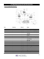
2.2 Aqualift® F description
The KESSEL Aqualift® F 400 Volt lifting station in single or twin pump variations is comprised of
the following systems.
1. Polyethylene collection chamber, gas and water tight with:
1. PEHD gas and watertight holding chamber with:
1.1 single or double wastewater pump(s) with 5 meter cable
1.2 Pneumatic pressure switch with 5 meter cable
1.3 Access / Cleaning port
1.4 Connection for DN 100 inlet
1.5 Connection for DN 70 ventilation (mandatory)
1.6 Connection for DN 40 manual emergency pump
1.7 DN 100 pressure pipe outlet with integrated backflow flap and release lever
1.8 Area for additional connection of inlet pipes
2. Electrical control unit (see illustration in Chapter 8)
3. Accessories (without illustration)
3.1 Securing brackets (for secure installation with sub-surface
3.2 Flexible coupling for attaching DN 100 Aqualift® F outlet to outlet piping.
A complete list of main pump parts is illustrated in Chapter 10.
7
3. Technical Data
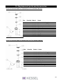
3.1 Dimensions
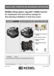
3.1.1 Single pump Aqualift® F, 1.1 kW, DN 100 outlet - Article Number 28645
Single pump Aqualift® F, 2.2 kW, DN 100 outlet - Article Number 28647
3. Technical Data
3.1.2 Twin pump Aqualift® F, 1.1 kW, DN 100 outlet - Article Number 28652
Twin pump Aqualift® F, 2.2 kW, DN 100 outlet - Article Number 28634
8
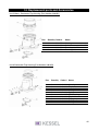
3. Technical Data
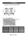
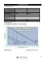
3.1.3 Twin pump Aqualift® F, 2.6 kW, DN 100 outlet - Article Number 28638
Twin pump Aqualift® F, 4.0 kW, DN 100 outlet - Article Number 28639
Twin pump Aqualift® F, 5,5 kW, DN 100 outlet - Article Number 28640
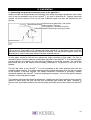
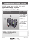
Performance curve for Aqualift® F Duo XXL
Height H (meters)
Type
Operating power P2
Total power usage P1
Voltage (direct)
Frequency
Amps
Cables
Wastewater temp.
Protection
Volume (cubic meters / hour)
400 V – 2,6 kW
2,6 kW
3,3 kW
400 V DC
50 Hz
5,6 A
5m
7 x 1,5 mm2
40 ° C
IP 68
400 V – 4,0 kW
3,5 kW
4,2 kW
400 V DC
50 Hz
8,2 A
5m
7 x 1,5 mm2
40 ° C
IP 68
400 V –5,5 kW
4,8 kW
5,6 kW
400 V DC
50 Hz
10,2 A
5m
7 x 1,5 mm2
40 ° C
IP 68
9
3. Technical Data
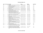
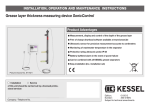
3.2 Pumps (Mono, Duo)
Type
Operating power P2
Total power usage P1
Voltage
Frequency
Operating current
Starting current
Fuse
Connection cables
Advised wastewater
temperature
Weight (pump only)
Protection
Operation
400 V – 1.1 kW
1.1 kW
1.4 kW
400 V – 2.2 kW
2.2 kW
2.7 kW
400 Volt DC
50 Hz
2.7 Amp
4.9 Amp
14.4 Amp
30.8 Amp
3 x 10 Amp
length - 5 meters, 1.5 square mm, 7 inner cables
35 deg C (95 deg C)
30 Kg
31 Kg
IP 68 (2 meter water head)
S1, 240 min max. run time
S3, 30% run time
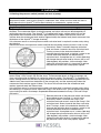
Performance curve
Qmin according to norm DIN 1986 (vmin = 0,7m/s) for DN 80
Qmin according to norm DIN 1986 (vmin = 0,7m/s) for DN 100
Height H (meters)
Volume (cubic meters / hour)
10
3. Technical Data
3.3 Operating Volume
As delivered, the Aqualift® F single pump will pump approximately 20 litres per activation. Aqualift®
F twin pump systems pump approx 50 litres per activation. The pumping levels can be changed by
setting the pneumatic switch - this will later be explained in this manual.
3.4 Electrical Control Unit
3.4.1 General technical information
Ambient conditions for control unit
Allowable temperature range - 0 to 50 deg C (32 to 122 deg F)
Humidity - 10 to 80 % (no condensation)
Max elevation - 2000 meters above sea level
Power consumption from electronics (without pump) -11 VA for single pump system
Power consumption from electronics (without pump) -15 VA for double pump system
Protection Class - Class 1
Protection Type - IP 54 (with closed control unit cover and factory gasket)
Protection Type - IP 21 (wall mounted without factory supplied cover)
3.4.2 Supply
Operating power
400 / 230 Volt 3 phase
50 Hz +- 10%
Power connection
Standard plug (from control unit - with 1.7 meter length)
Required protection
max. 16 A (to be supplied on site)
11
4. Installation
When the shipment arrives, please inspect it immediately for damages which may have
been caused during transport / shipping!
Important: KESSEL Aqualifts with single pumps weigh approximately 45 Kg (approx 100 pounds)
and double pump systems weight approximately 84 Kg (approx. 185 Kg). The Aqualift® F units
should be handled by at least two people equipped with appropriate equipments (e.g. safety
shoes, back support, etc.).
Important After the receiving the Aqualift® F but before installation, it is important that the control
unit is stored in a dry, frost free area until time of connection.
Installation area: The KESSEL Aqualift® F lifting station is to be installed on a sturdy floor in a
frost free area. The accompanied control unit is designed to be wall mounted in a dry, flood
protected, frost protected room.
4.1 Installation location tips
In order to provide easy of installation, operation and maintenance it is important that the Aqualift®
F is installed in a location where it is easily accessible from all sides. According to DIN 1986 a
minimum distance of 60 cm should be kept free completely surrounding the Aqualift® F (including
above the unit).
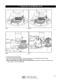
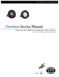
The Aqualift® F should be installed level on a solid floor. To further dampen the noise level of the
Aqualift® F (during operation) it is recommended that the unit is placed on top of a rubber
dampening matt (available from KESSEL). The Aqualift® F is to be securely bolted to the floor with
the supplied anchors and bolts to prevent it from being moved or shifted.
Behälter-Hebeanlage = Aqualift® F storage
chamber
Dämpfungsmatte = Vibration dampening matt
(optional)
Befestigungswinkel = Securing bracket
Bodenbefestigung = floor mounting
Boden = floor
12
4. Installation
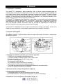
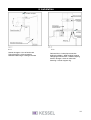
4.2 Pipe connections
All drainage pipes connected to the Aqualift® F should be laid with the proper slope so that they run
completely empty (no standing water in pipes). All connected pipes should be properly secured to
prevent vibration and provide a flexible connection to the Aqualift® F body.
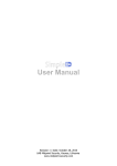
Two types of connection to the Aqualift® F:
I - Connecting using the preformed, closed inlets.
The Aqualift® F has preformed (closed) inlet stubs for the main inlet, ventilation pipe and the
emergency manual pump - as seen in Illustration A. The closed tip of all needed preformed inlets
should be cut off with a standard saw as seen in Illustration C. A standard drainage pipe (HT pipe
with gasket) can then be push-fit over the open inlet. An additional alternative to connecting pipes
is to use rubber couplings - these can provide additional flexibility and help prevent the preformed
inlet stubs from becoming deformed from forces / stress caused by pumping. If couplings are used
it is important to insert a metal reinforcement ring inside the preformed inlet (as seen in Illustration
D).
Ill. A: single pump unit
Ill B: double pump unit
Entlüftung = Ventilation port
Zulauf = Inlet connection
Anschluß Handmembranpumpe = Emergency hand pump connection
Einzelanlage = Single pump unit
Doppelanlage = Double pump unit
13
3.4. Installation
Ill. C
Stutzen absägen = Saw off outlet stub
Zulauf-Anschluß = Inlet connection
Behälter-Hebeanlage = Storage chamber
Ill. C
Rohranschluß = Outlet pipe connection
Schlauchschellen = Steel coupling fastener
Übergangsschlauchstück = Rubber coupling
Stutzen absägen = Saw off outlet stub
Stützring = Interior support ring
14
4. Installation
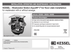
II - Connecting using the flat connection areas on the Aqualift® F.
Additional inlets can be connected to the Aqualift® F by drilling out properly sized holes (with a hole
saw) in the flat connection area of the Aqualift® F (as seen in illustration E). Properly sized inlet
gaskets are then inserted in the cut out hole. Additional pipes can then be inserted into the
gaskets.
Rohrdurchführungsdichtung = Inlet gasket
Rohranschluß = Inlet pipe
Öffnung gebohrt = Sawed out inlet hole
Behälter-Hebeanlage = Storage chamber
Ill. E
Important - if additional pipes are connected to the flat connection areas, it is important that they
are not too low. The bottom of all attached inlet pipes should be, at the lowest, equal to normal
operational wastewater level inside the Aqualift® F chamber. This will prevent stagnant water and
the build-up of solids in inlet pipes which have been attached too low.
All inlet pipes should be laid with the appropriate slope (according to DIN 1986). The DN 70
ventilation pipe is critically important to the proper operation of the Aqualift® F. The ventilation pipe
prevents positive and negative air pressures from building up inside the chamber. The ventilation
pipe should be run to the exterior of the building, preferably to a high point on the roof of the
building.
The DN 100 outlet of the Aqualift® F is to be connected to the outlet pressure pipe with the
included rubber coupling. The rubber coupling should be fitted approximately 4 cm over the outlet
of the Aqualift® F and then secured. This rubber connection is important in providing a flexible
connection between the Aqualift® F and the outgoing pressure pipe - this will also greatly reduced
vibrations in the outlet pressure pipe.
The outgoing pressure pipe should be plumbed to a height over the local backwater level (normally
ground or street level) and then into the main wastewater pipe exiting the home / building. A
closure valve should be installed in this pressure pipe, preferably close to the outlet of the Aqualift®
F.
15
4. Installation
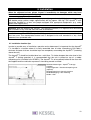
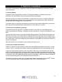
4.3 Setting the pressure switch (controls on level of pump)
Caution - Aqualift® F must be completely disconnected from its power source before any work on
the pressure switch, control unit or pump is undertaken. Also, make sure that while this work is
being done that the Aqualift® F will not be mistakenly re-connected to a power source.
Single Pump Unit
The pressure switch is designed to monitor the wastewater level inside the Aqualift® F storage
chamber. The wastewater levels at which the pump and alarm activate can be changed by resetting the pressure switch. The Aqualift® F is supplied with factory settings which turn on the
pump when the wastewater level reaches approximately the 160mm level and the alarm will
activate when the wastewater level reaches approximately the 200mm level (levels measured from
the bottom of the Aqualift® F storage chamber).
If for whatever reason a custom pressure switch activation level is required it can be set by doing
the following:
Remove the cover of the pressure switch and find the two setting screws (marked 1 and 2 in the
illustration). Screw 1 controls the pump activation
level and screw 2 controls the alarm activation level.
Turning a screw in the clockwise direction will
increase the activation level as turning a screw in the
counter-clockwise direction will decrease the
activation level. A complete turn of a screw (360 deg)
will change the activation level by 20 mm (half a turn
(180 degrees) will provide a 10 mm change). After
setting the activation levels it is important to replace
the pressure switch cover and properly tighten.
Twin Pump Unit
The twin pump Aqualift® F is equipped with two pumps and a total of three pressure switches to
control Pump 1 ON, Pump 2 ON and the alarm. The wastewater levels at which the pumps and
alarm activate can be changed by re-setting the pressure switch. The Aqualift® F is supplied with
factory settings which turn on the first pump when the wastewater level reaches approximately the
180mm level (measured from the bottom of the storage tank) and the second pump when the
wastewater level reaches approx 210mm. The alarm will activate when the wastewater level
reaches approximately the 270mm level.
If for whatever reason a custom pressure switch activation level is required it can be set by doing
the following (it is important not to adjust the Pump 1 ON level too low - this will prevent the pump
from starting too often. Also keep a respectable difference between the Pump 1 ON and Pump 2
ON levels):
Remove the cover of the pressure switch and find the
three setting screws (marked 1, 2 and 3 in the
illustration). Screw 1 controls the Pump 1 ON
activation level and screw 2 controls the Pump 2 ON
activation level. Screw 3 control the Alarm activation
level. Turning a screw in the clockwise direction will
increase the activation level as turning a screw in the
counter-clockwise direction will decrease the
activation level. A complete turn of a screw (360 deg)
will change the activation level by 20 mm (half a turn
(180 degrees) will provide a 10 mm change). After
setting the activation levels it is important to replace
the pressure switch cover and properly tighten.
16
5. Electrical connections
The cables for the pump(s) and pressure switch have been connected to the Aqualift® F control
unit at the factory.
5.1 General Notice
All electrical work concerning the Aqualift® F should be handled by a licensed professional
electrician and should follow all local and national electrical guidelines.
After the control unit has been wall-mounted it is important that the cover is securely closed and
that the cable entering the control unit are secured to the wall to prevent the cables from being
accidentally pulled or tugged out of the control unit.
The power cables for the pump and the pressure switch should not be installed next to each other this will prevent interference which could potentially cause false starts / alarms.
5.2 Control unit installation / mounting
The control unit for the Aqualift® F should be installed in a frost free, dry, well ventilated room
which is protected from flooding. It should be securely mounted on a sturdy wall, preferably at eye
level.
To mount the control unit first place the provided drilling template on the desired wall location and
drill out the four holes. The screw holes for fastening the control unit to the wall are located in the
four corners of the control unit (the control unit cover must first be opened in order to access these
four screw holes). Information concerning the connection of the cables can be found in section 5.3
of this User's Manual.
After the control unit is mounted be sure to securely close the cover.
5.3 Control unit cable connections
Cables for the pump and the pressure switch have already been connected at the factory. If other
systems, such as a potential free contact, need to be installed please do in the following manner:
unscrew the desired plastic hand nut from the bottom of the control unit and place over the wire
which is to be connected. With a sharp instrument, pierce the rubber seal (see illustration a). Now
insert the cable through the pierced rubber seal and insert until the required amount of cable length
is inside the control unit. Replace the plastic hand nut and tighten. Cables can know be connected
to their corresponding jack by the method illustrated in illustration c.
The pump and pressure switch have a 5 meter cable which is connected to the Aqualift® F control
unit. Only the pump's cable can be lengthened using a VDE certified connection.
17
5. Electrical connections
The pressure cable is a special cable containing a small hollow pipe used to equalize pressure
fluctuations in the pressure switch. Important points concerning the pressure switch cable:
The pressure switch cable can be shortened to any desired length but MUST NOT be
lengthened. Any custom cable lengths must be ordered from KESSEL.
The cable for the pressure switch should have a constant and equal downward slope from the
control unit to the pump (no zig-zags or positive slopes (upwards) is allowed.
The plastic hand nut sealing the pressure switch cable with the control unit must not be tightened
over a torque of 2.5 Nm (this could put unwanted pressure on the hollow equalization tube).
Not abiding by the above three conditions could cause the pressure switch as well as the pump
to malfunction.
Cable connection table for Aqualift® F 400 Volt (single pump) system. For additional
information concerning these connection please see Chapter 8 of this manual.
Connections
Power Cable
Pump cables
Motor temp sensor
Pressure switch
'On' and 'Alarm'
Control unit battery
Description
Power cables L1 / L2 / L3 / N and PE must be connected to the
upper row of grey connection jacks. Please note that jacks N and
PE MUST BE connected.
The power cable must be connected to an all-polar on / off
switch
The maximum fuse rating for each of the 3 phases is 16 Amps
Improper cable connection could damage or destroy the unit.
Pump cables U / V / W is to be connected to the ABB Protection
B6-30-10 by connecting to the T1/T2/T3 screws to the LEFT of
the motor protection switch. Be sure that the phases are properly
connected.
PE should be connected to the lower level of the grey power
connection jacks (marked 'Platinenaufdruck'
Entry TF - Cable 4 from the motor cable is to be connected to on
the left side of the TF entry. Cable 5 to be connected to the right
side of the TF entry.
Entry E7 – the bridge is to be left alone.
The cables for the pressure switch should be connected to their
corresponding jacks - connect the white cable on the right
side and the brown cable on the left side on the 'Ein'
entry. On the 'Alarm' entry connect the green cable to the right
and the yellow cable to the left.
The jacks are marked with a switch symbol.
The battery for the control unit should be a NiCd-9V-Block Type
IEC 6F22. This battery serves to provide warning and alarms in
the case of a power failure. Do not use a standard battery - this
must be a rechargeable batter with the above characteristics.
Only replace or remove the battery when the control unit is not
connected to a power source. Make sure polarity is correct.
If a rechargeable batter with no power (dead / empty battery) is
laced in the control unit it will take at least 36 hours to reach a full
charge.
18
5. Electrical connections
Cable connection table for Aqualift® F 400 Volt (twin pump) system. For additional
information concerning these connection please see Chapter 8 of this manual.
Connections
Power Cable
Pump cables
Motor temp sensor
Pressure switch
'On 1', 'On 2' and 'Alarm'
Control unit battery
Description
Power cables L1 / L2 / L3 / N and PE must be connected to the
upper row of grey connection jacks. Please note that jacks N and
PE MUST BE connected.
The power cable must be connected to an all-polar switch which
is clearly marked as the on/off switch of the Aqualift® F.
The maximum fuse rating for each of the 3 phases is 25 Amps
Improper cable connection could damage or destroy the unit
Pump cables U / V / W is to be connected to the ABB Protection
B6-30-10 by connecting to the T1/T2/T3 screws below the
motor protection switch (Pump1 left, Pump 2 right). Be sure that
the phases are properly connected.
PE should be connected to the corresponding upper level power
connection jacks marked Platinenaufdruck, colour coded
Entry TF1 - Cable 4 from the motor cable from Pump 1 is to be
connected to on the right side of the TF1 entry. Cable 5 to
be connected to the left side of the TF entry.
Entry TF2 - Cable 4 from the motor cable from Pump 2 is to be
connected to on the right side of the TF2 entry. Cable 5 to
be connected to the left side of the TF2 entry.
Entry E7 - The bridge is to be left alone
Entry E8 - The bridge is to be left alone
The cables for the pressure switch should be connected to their
corresponding jacks - connect the white cable on the right
side and the brown cable on the left side on the 'Ein 1'
entry. Connect the green cable to the right and the yellow cable
to the left of the 'Ein 2' entry. On the 'Alarm' entry connect the
grey cable to the right and the pink cable to the left.
The jacks are marked with a switch symbol.
The battery for the control unit should be a NiCd-9V-Block Type
IEC 6F22. This battery serves to provide warning and alarms in
the case of a power failure. Do not use a standard battery - this
must be a rechargeable batter with the above characteristics
Only replace or remove the battery when the control unit is not
connected to a power source. Make sure polarity is correct
If a rechargeable batter with no power (dead / empty battery) is
placed in the control unit it will take at least 36 hours to reach a
full charge.
After all control unit connections have been made be sure to close the cover to the control unit and
secure with the 4 screws.
19
5. Electrical connections
5.4 Impeller / Motor rotation
Before placing the Aqualift® F into operation, check to make sure that the rotation of the motor /
impeller is correct. If the impeller turns in the wrong direction either switch L1 with L2 or switch L2
with L3.
5.5 Motor protection switch
The motor protection switch must be set to handle the appropriate power rating listed section 3.1 of
this User's Manual.
5.6 Custom pump settings
The standard settings can be custom set by adjusting the S604 switch ( 4-way DIP switch each
with ON/OFF setting )
Different settings are not permitted.
S604/1
S604/2
S604/3
S604/4
level controlled
with OFF level switch
rotation monitor on
anti-blocking function on
OFF
OFF
OFF
OFF
ON
ON
ON
ON
S604/1
S604/2
S604/3
S604/4
level controlled
without OFF level switch
rotation monitor on
anti-blocking function
OFF
ON
ON
ON
ON
The pump start delay time can be custom set by adjusting the S601 switch. This delay can be set
between 1 and 3 seconds in 0.2 second increments. (tolerance +- 0.1 seconds)
The maximum running time can be custom set by adjusting the S602 switch. This can be set
between 40 and 640 minutes in 40 minute increments (tolerance +- 4 minutes)
The pump stop delay time can be custom set by adjusting the S603 switch. This can be set
between 0.5 and 8 seconds in 0.5 second increments (tolerance +- 0.1 seconds)
Before making any of the above adjustments make sure to disconnect the Aqualift® F from its
power source. Any setting changes should be handled by a licensed professional and should be
documented in this User's Manual.
5.7 Completion of electrical work
After all electrical work has been completed on the Aqualift® F or the control unit make sure
replace the cover and the transparent cover of the control unit.
20
6. Commissioning
6.1 General Instructions
Please follow DIN 1986 Part 31 when commissioning pumps / lifting stations
Caution - Before commissioning the Aqualift® F make sure that all inlet pipes as well Aqualift® F
storage chamber and the pump is free from metal, sand or any other potentially damaging debris.
Before commissioning, the Aqualift® F must be filled with water / wastewater to at least the
elevation of the ventilation port on the pump housing.
Pump must not intake air!
Only place the Aqualift® F into operation after it has been thoroughly checked to assure that
installation and pipe and electrical connection have been properly made. Make sure that all closure
valves are fully open before starting.
Important - the commissioning of the Aqualift® F must be handled by a licensed professional.
Make sure to follow all safety instructions in Part 1 of this User's manual and do not place the
Aqualift® F in operation if the pump, control unit or cables show any signs of damage.
Important - All screws / bolts should be tighten to a maximum of 3 Nm
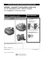
6.2 Outlet Pressure Flange
The outlet pressure flange is equipped with a backflow flap and a manual opening lever. During
standard operation, the backflow flap must be in the operational position as seen in Illustration 1.
During pumping the flap will be forced open by the pressure of the outgoing wastewater (as seen
by the dotted lines).
Ill. 1
21
6. Commissioning
6.3 Description of operation
6.3.1 'Auto' mode
Single pump unit
The single pump Aqualift® F is in standard operating mode when the control unit switch is set to
'Auto' and no failures or warnings are displayed. As the wastewater level inside the Aqualift® F
storage chamber rises it increases the inside air pressure on the pressure control switch which will
activate when the wastewater level reaches a certain height inside the chamber. After activation of
the pressure switch the pump start delay time begins to count down and when this delay is over
the pump begins to run. As the wastewater level decreases the air pressure inside the pressure
switch also decreases until it reaches a point when the pressure switch will 'de-activate'. After the
pressure switch has 'de-activate', the pump start delay time begins to count down and when this
delay is over the pump stops running. In the case that the pump runs for longer than the set
maximum pump run time, the pump will turn off and at this time the 'Laufzeit' LED will turn on to let
the operator know that the motor has run to its maximum run time. The warning will remain until the
'Alarm Reset' button is pressed. Pressing the 'Alarm Reset' button will then allow the pump to
restart.
Double pump unit
The double pump Aqualift® F is in standard operating mode when the control unit switch is set to
'Auto' and no failures or warnings are displayed.
Alternating Operation
As the wastewater level inside the Aqualift® F storage chamber rises it increases the inside air
pressure on the pressure control switch which will activate when the wastewater level reaches a
certain height inside the chamber. After activation of the pressure switch the pump start delay time
begins to count down and when this delay is over the pump begins to run. As the wastewater level
decreases the air pressure inside the pressure switch also decreases until it reaches a point when
the pressure switch will 'de-activate'. After the pressure switch has 'de-activate', the pump start
delay time begins to count down and when this delay is over the pump stops running. The next
time the pressure switch activates the second pump will operate. This process will continue with
the pumps operating alternatingly.
Parallel Operation
As the wastewater level inside the Aqualift® F storage chamber rises it increases the inside air
pressure on the pressure control switch which will activate when the wastewater level reaches a
certain height inside the chamber. After activation of the pressure switch the pump start delay time
begins to count down and when this delay is over the pump begins to run. If the wastewater level
continues to rise (i.e. - more wastewater is entering the chamber as the single pump can pump out)
the pressure inside the pressure switch will continue to rise and if it reaches a certain level the
second pump will begin to operate (after the pump start delay time has passed). Both pumps will
continue to run simultaneously until the pressure inside the pressure switch falls below the original
'Pump 1 On' level and the pump stop delay time has passed.
22
6. Commissioning
In the case that one or both of the pumps runs for longer than the set maximum pump run time, the
pump(s) will turn off and at this time the 'Laufzeit' LED will turn on to let the operator know that the
motor has run to its maximum run time. The warning will remain until the 'Alarm Reset' button is
pressed. Pressing the 'Alarm Reset' button will then allow the pump to restart.
6.3.2 '0' Mode
When the control unit is set to the '0' mode the pump(s) will not operate although the warning and
failure displays on the control unit will continue to function.
6.3.3 'Hand' Mode
When the control unit is set to the 'Hand' mode the pump will begin (or continue) to run (regardless
of the wastewater level inside the Aqualift® F) until the switched off of the 'Hand' mode setting.
Attention - A pump running without water circulating through it causes increase temperatures and
a drastic increase on the wear and tear of the motor. Excessive dry running of the pump(s) (above
5 minutes) can lead to irreparable damage to the pump. This damage is easily detectable and is
not covered under the Aqualift® F warranty.
6.4. Operational Test
The functions of the Aqualift® F, dependant on wastewater levels inside the unit, should be tested
after installation by filling up the Aqualift® F with wastewater to specific levels. Filling of the unit
should take place by draining fixures connected to the unit. During the filling and emptying
procedure the control unit of the Aqualift® F should be set to the “Betriebsart” – “0” setting.
23
7. Inspection and Maintenance
The Aqualift® F should be visually checked once per month by the operator. This involves a visual
check to make sure no cable are damaged and that the holding chamber is water tight. During this
inspection, a fixture connected to the Aqualift® F (such as a sink or toilet) should be run until the
Aqualift® F pump activated - this will confirm that the float switch system and the pump is operating
properly.
Thorough inspections should take place at regular intervals according to DIN 1986 Part 31. These
inspections should only be handled by a licensed professional. Repairs of the Aqualift® F should
only be handled by the manufacturer. The inspection should include the following:
Visual inspection of the entire unit including the pump and accessories.
Cleaning of the entire unit including the pump.
Inspection of entire unit including pump housing for exterior damage or wear and tear.
Check pump to make sure movable parts move freely and that now deposits have developed.
Check all cables of the Aqualift® F to make sure they are in excellent condition.
Check all connections of the Aqualift® F to make sure they are firm and water tight.
Important - all screws and bolt on the Aqualift® F should be tightened to a maximum torque of 3
Nm.
The above listed inspection should also be carried out after the Aqualift® F has been stored or not
operated for an extended period of time.
7.1 Pump Information
The Aqualift® F pump should be inspected in regular intervals. In the case that pump operates
louder than normal or loses pumping efficiency the pump and its impeller must be well cleaned and
inspected. To do this the 4 holding screws for the pump must be removed (as seen in Illustration
10.2.1) and the entire pump taken out of the chamber for inspection. During this inspection it is
important to check that the ventilation port on the pump body is open and free of any debris.
7.2 Backflow Preventer Information
The backflow preventer (seen in Illustrations 2 and 3 below) can be used to empty the vertical
section of the outlet pressure pipe. This must be done in order to disconnect the Aqualift® F from
the outlet pressure pipe (As seen in Illustration 4). With a size 8 (15 mm) wrench, turn the bolt
clockwise until the wastewater collected in the outlet pressure pipe begins running back into the
Aqualift® F chamber. After all the wastewater is out of the vertical section of the pressure pipe it is
important to close the flap again be turning the bolt counter-clockwise until closure.
24
7. Inspection and Maintenance
Ill. 4
Ill. 3
Ill. 4
Ill. 5
7.3 Control Unit Information
Be sure to unplug the Aqualift® F control unit before any maintenance work is done.
Repairs should only be handled by the manufacture.
After maintenance work is done, be sure that the control unit cover is closed and that the four
cover screws are firmly tightened.
25
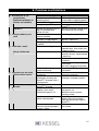
8. Problems and Solutions
The following checks and shut-down procedures should only be handled by a licensed
professional.
8.1 General Problems
1
Problem
Pump does not start
Reason
Control unit not plugged in
Over load or max temp
exceeded, motor is blocked
Motor difficult to turn
No power
2
Pump operates but alarm Aqualift® F is receiving too
much wastewater
level is reached
Aqualift® F does not pump
enough wastewater
3
Pump operates rough or
noisy and LED “Phase /
Drehfeld” lights
Pump operates rough or
noisy and LED “Phase /
Drehfeld” does not light
Ventilation improper or not
connected
Wrong motor rotation
For twin pump units both
motors rotate wrong
Low pump performance
to due damage
Wrong motor rotation
For twin pump units both
motors rotate wrong
Solution
Plug in control unit
Switch control unit to “Auto”
Remove motor, remove
obstacle from impeller /
pump housing – caution
pump may be hot!
Check for free rotation
of impeller – call for
professional repair
Check fuses and electrical
cables that they are properly
attached
Check that all 3 phases are
fonctioning.
Check to see if multiple fixtures
are being drained simultaneously
– if so, temporarily do not use
certain fixtures – or, if necessary
disconnect fixtures from
Aqualift® F
- Check for blockage in impeller
or pump housing
- Check for blockages in outlet or
pressure pipe
- Impeller is worn, replace
impeller / replace pump
- Aqualift® F improperly installed,
consult KESSEL Customer
Service
Repair or install proper
ventilation pipe
Check impeller rotation
Switch cable polarity
Switch 2 phases on main cable
in control unit
Check motor and impeller
Replace if necessary
Check impeller rotation
Switch cable polarity
Switch 2 phases on motor cable
in control unit
26
8. Problems and Solutions
Problem
4
Wastewater is not
pumped away.
Backwater problems in
fixtures connected to
Aqualift® F
5
Pump suddenly runs
loud
6
Bad odor / smell
Sharp / acidic odor
7
System runs too much
Starts without reason
8
System does not stop
running
Reason
Aqualift® F is not plugged in
Cable to control unit not
receiving power
Level switch malfunction
Inlet(s) to Aqualift® F blocked
Solution
Plug in Aqualift® F
Check outlet and fuse
Insure outlet is supplying power
Check and clean float switch
Check and clean inlet(s) to
Aqualift® F
Wastewater temperature too Reduce wastewater temperature
high for extended time
(run cold water into system)
period (15 min)
Phases on house electrical
Check impeller rotation
system switched
Damage to pump parts
Check pump and impeller
caused by foreign objects
Replace if necessary
Foreign object stuck in pump Remove foreign object
/ impeller
System is not airtight
Ventilation, inlet, outlet,
inspection port, float switch seal
– check for leaks
Pump not leak proof
Check pump and contact
customer service / replace pump
if necessary
Motor(s) too hot overloaded Check motor and pump for ease
of rotation
Too frequent starting / stopping
of the motor
Too much incoming wastewater
Contactor too hot due to
Check Aqualift® F for switch
switch malfunction
malfunction
Too much incoming
Check for cause of excessive
wastewater
incoming wastewater
Backflow prevent defective
Check backflow preventer for
blockage or improper function
wastewater returning into
Aqualift® F chamber after it
is pumped out
Foam build up inside
Reduce use of soap or cleansers
Aqualift® F chamber
Interior of chamber / pump / Completely clean all parts coated
impeller / float switch
with grease / fat.
coated with grease / fat
Reduce amount of grease
enterring system
Ventilation tube inside float
Check float switch cable for kinks
switch cable blocked
/ bends. Make sure properly
layed with continuous slope to
Aqualift® F
Pressure switch system dirty Remove pressure switch, clean
Pressure switch improperly
tube coated
connect / defect
27
8. Problems and Solutions
8.2 Irregular level conditions
Problems or failures with the level switches can often be detected by the control unit and be
displayed while in the Auto mode. If the control unit detects an impossible level switch situation, the
'Laufzeit / Niveau' LED will begin to blink. This can be confirmed and cancelled by pressing the
'Alarm Reset' button if the problem has been fixed or the wastewater level has changed and this
'impossible' level is no longer present. Problems with the 'Alarm' closure switch and the opening of
the 'On' level switch cannot be detected.
Single Pump Aqualift® F
The level switches of a single pump Aqualift® F cannot tell the difference between an 'On' level
switch which does not activate and an 'Alarm' switch which does not turn off. In the case that the
'Alarm' level is reached without the 'On' level activating, a level failure will be displayed and the
motor / pump will not be turned on. If, in this situation, the 'On' level does activate - then the pump
will turn on. When the 'On' level switch again opens the pump will turn off.
Double Pump Aqualift® F
'On' level switch which does not close (activate)
An alarm will be activated after the wastewater level reaches the 'On 2' level. In the case that
the 'Alarm' level is exceeded will activate both pumps. When the wastewater level falls below
the 'On 2' level both pump will be turned off.
'On 2' level switch which does not close (activate)
An alarm will be activate after the wastewater level exceeds the 'Alarm' level. At the same time
both pumps will be activated. Both pumps will remain in operation until the wastewater level falls
below 'On 1' level.
Constantly closed (activated) 'On 2' level switch
An alarm will activate after the wastewater level has fallen below the 'On 1' level. One pump will
activate after the 'On 1' level has been reached and the second pump will also be activated after
the 'Alarm' level has been reached.
Constantly closed (activated) 'Alarm' level switch
Am alarm will activate after the 'Alarm' level switch has been activated and at the same the
wastewater level has fallen below the 'On 2' level. This will result in a constant 'Alarm' warning.
The actual audible alarm can be confirmed and cancelled by pressing the 'Alarm Reset' button
on the control unit. The 'Alarm' relay switch will remain as it is until the problem has been
corrected. One pump will be activated after the 'On 1' level has been exceeded and the second
pump will also activate after the 'On 2' level has been exceeded. Both pump will turn off after the
wastewater level has fallen below the 'On 1' level.
28
8. Problems and Solutions
8.3 Disturbances / Internal controls
The control unit continuously monitors the signals from the motor protection switches and the
motor temperature sensors. In the case of a disturbance the pump will either be shut off or
prevented from starting. This will result in a corresponding alarm and the lighting of an LED.
8.3.1 In the case that L2 and / or L3 fail, the 'Phase/Drehfeld' LED will continuously light and
the 'Störung' relay will activate. Since the control of L1 is still active, the failure of L1 will not be
displayed.
8.3.2 In the case that a motor protection switch is activated either manually, by a short circuit
or by an overload, the 'Motorschutzschalter' LED will activate ('Pumpe . . . MSS/Temp' LED).
8.3.3 Motors of the Aqualift® F contain a temperature sensor which will activate when the
otor temperature reaches 110 degrees Celsius and the motor will automatically be shut
off. At this point the 'Motortemperatur' LED ('Pumpe . . . MSS/Temp' LED with double
pump units) will signal. As soon as the motor has cooled to an appropriate temperature
the motor will automatically restart.
8.4 'Alarm' Warnings
There are two situations which will result in an Alarm warning
1.Wastewater in the Aqualift® F which has exceeded the 'Alarm' level will cause the alarm to
activate. This can be turned off by pressing the 'Alarm Reset' button on the control unit. If the
wastewater level falls below the 'Alarm' level then the alarm will automatically be turned off.
2.The alarm will also be activated in the case of a power failure. This alarm can be turned off by
pressing the 'Alarm Reset' button on the control unit.
8.5 What to do when . . . .
The motor protection switch is activated - Open the transparent cover of the control unit and
press the 'START' button. If the motor protection switch reactivated immediately after being
pressed please contact a licensed electrician.
The Aqualift® F no longer reacts to incoming signals (for example from the float switches) - unplug
the control unit of the Aqualift® F for at least 10 seconds and then plug back in. In the case that
the Aqualift® F still no longer response to incoming signal please contact a licensed
professional.
29
9. Control Unit
9.1 Control unit for single pump Aqualift® F
9.1.1 Description of displays and operational button on control unit
LED’s
Normal operation
(user information)
Warning
(for installer)
Buttons
Hand - 0 - Auto
Alarm reset
Betrieb
'Alarm' level
'On' level
'Off' level
Pumpe
Phase
green
yellow
yellow
yellow
green
red
Motor protection
Motor temperature
red
red
Running time/level
red
Rotating switch
button
power supply functioning
'Alarm' level reached
pump on level reached
no function
pump outlet activated
constant - phase not active
blinking - rotating field
problem
motor protection activated
blinking - 'Temperature A'
(TF)
constant - running time
failure
blinking - level failure
Chooses operation type
Turns off alarm from level
switch
Turns off level failure alarm
Turns of motor
temperature alarm
Motor protection
switch
switch
Activated when pump
overloads
The control buttons can be accessed by removing the transparent cover of the Aqualift® F control
unit. The cover should only be removed and the control buttons accessed by a licensed
professional.
During the time that the transparent control unit cover is removed, the control units protection class
is reduced. In the case that a humid condition or splashing water may be present - first unplug the
control unit before removing the transparent cover.
Be sure that the transparent cover is properly replaced and secured so that the proper protection
class is ensured.
30
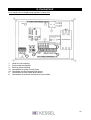
9. Control Unit
9.1.2 Interior view of single pump Aqualift® F control unit
1.
2.
3.
4.1
4.2
5.
6.
Holes for wall mounting
Power cable connections
Back up battery housing
Connections for pump / motor power
Connection for pump temperature sensor
Connections for float switch level sensors
Connections for external warning and alarm notifies.
31
9. Control Unit
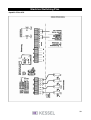
9.1.3 Connecting plan for single pump Aqualift® F
32
9. Control Unit
9.2 Control unit for double pump Aqualift® F
9.2.1 Description of displays and operational button on control unit
LED’s
Normal operation
Warning
Buttons
Hand - 0 - Auto (Pump 1)
Hand - 0 - Auto (Pump 2)
Alarm reset
Betrieb
'Alarm' level
'On 2' level
'On 1' level
'Off' level
Pump1
Pump2
Phase
green
yellow
yellow
yellow
yellow
green
green
red
power supply functioning
'Alarm' level reached
pump 2 on level reached
pump 1 on level reached
no function
pump outlet 1 activated
pump outlet 2 activated
constant - phase not active
blinking - rotating field
problem
constant - Pump 2 motor
protection switch activated
blinking - Pump 2 thermal
switch
constant - Pump 1 motor
protection switch activated
blinking - Pump1 thermal
switch
constant - running time
failure
blinking - level failure
Pump 2
MSS/Temp
red
Pump 1
MSS/Temp
red
Running
time/level
red
Rotating switch
Rotating switch
button
Chooses Pump 1 operating type
Chooses Pump 2 operating type
Turns off alarm from level switch
Turns off level failure alarm
Motor protection switch 1
Motor protection switch 2
switch
switch
Turns of motor temperature alarm
Activated when pump overloads
Activated when pump overloads
The control buttons can be accessed by removing the transparent cover of the Aqualift® F control
unit. The cover should only be removed and the control buttons accessed by a licensed
professional.
During the time that the transparent control unit cover is removed, the control units protection class
is reduced. In the case that a humid condition or splashing water may be present - first unplug the
control unit before removing the transparent cover.
Be sure that the transparent cover is properly replaced and secured so that the proper protection
class is ensured.
33
9. Control Unit
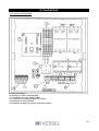
9.2.2 Interior of Control Unit
2 Power connection
3 Housing for battery (rechargeable)
4.1 Connection for pump power cables
4.2 Connection for pump temperature sensors
5 Connection for float switches
6 Connection for external warning and alarm notifiers
34
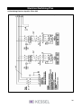
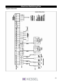
9. Control Unit
9.2.3 Connecting plan for double pump Aqualift® F
35
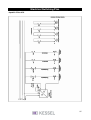
Electrical Switching Plan
9.3 Switching Plan for Aqualift® F Duo XXL
36
Electrical Switching Plan
Aqualift® F Duo XXL
37
Electrical Switching Plan
Aqualift® F Duo XXL
38
Electrical Switching Plan
Aqualift® F Duo XXL
39
Electrical Switching Plan
Aqualift® F Duo XXL
40
10. Replacement parts and Accessories
10.1 Accessories
Description
Emergency hand pump
Rubber connection couplings
Stainless steel pipe supports
Flange-rubber connection
Flange-sleeve adapter
Closure cover (when pump is removed)
Shut-off valve
Shut-off valve for emergency hand pump
Rubber vibration dampening matt (for under
Aqualift® F)
Rubber inlet seal (for additional inlets into
Aqualift® F)
Hole saw attachment for drill DN 50 - DN 150
Batteries
Shut-off device for single pump units
Shut-off device for double pump units
Order #
Single pump unit
28680
28660
28661
28662
28663
28653
28654
28655
28656
28657
28658
28678
28687
28688
28689
28681
28692
Double pump unit
DN 50
28693
850114
DN 70
DN 100
DN 125
DN 150
850116
850117
850118
850119
50100
20230
28683
28694
DN 40
DN 70
DN 80
DN 100
DN 70
DN 100
DN 80
DN 100
DN 100
DN 150
DN 80
DN 100
DN 150
DN 100
DN 100
41
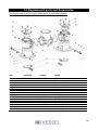
10. Replacement parts and Accessories
10.2 Replacement parts
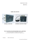
10.2.1 For single pump Aqualift® F
Pos.
Quantity
Oder #
Name
1
2
3A
3B
4
5
1
1
1
1
1
1
206-004
206-127
206-129
206-128
240-051
206-017
6
7
8
1
1
1
206-018
206-048
003-155
9
2
003-144
10
11
12
13
14
15
16
17
18
19
20
21
22
2
1
1
1
1
16
4
2
2
2
8
8
8
206-021
206-042
049-010
049-011
049-005
206-090
017-095
206-055
017-114
206-051
206-074
017-199
017-012
Chamber for single pump
Pump flange assembly (complete)
Complete motor 1.1 KW / 400 volt
Complete motor 2.2 KW / 400 volt
Housing for backflow flap DN 100
Complete pressure switch (for 1
pump)
Inspection port cover
Control unit (for single pump)
Rubber pipe connector D = 110 x
6 for DN 100
Connector fasteners D = 120 (for
DN 100)
Floor fastener
Seal for pump flange
Seal for pressure switch
Seal for inspection port
Roll ring
PT-fastening screws
Fastening bolts
Half round wooden screws
Washers
Screw housing
PT-fastening screws
Fastening bolts M8x25
Washers
42
10. Replacement parts and Accessories
10.2.2 For double pump Aqualift® F
Pos.
Quantity
Order #
Name
1
2
3A
3B
4
1
2
2
2
1
206-005
206-127
206-129
206-128
240-056
5
1
206-022
6
7
8
1
1
1
206-018
206-049
003-155
9
2
003-144
10
11
12
13
14
15
16
17
18
19
20
21
22
2
2
1
1
2
30
14
2
2
2
8
14
14
206-021
206-042
049-010
049-011
049-005
206-090
017-095
206-055
017-114
206-051
206-074
017-199
017-012
Chamber for double pump
Pump flange assembly (complete)
Complete motor 1.1 KW / 400 volt
Complete motor 2.2 KW / 400 volt
Housing for twin backflow flaps
(DN100)
Complete pressure switch (for 2
pumps)
Inspection port cover
Control unit (for double pump)
Rubber pipe connector D = 110 x
6 for DN 100
Connector fasteners D = 120 for
DN 100)
Floor fastener
Seal for pump flange
Seal for pressure switch
Seal for inspection port
Roll ring
PT-fastening screws
Fastening bolts
Half round wooden screws
Washers
Screw housing
PT-fastening screws
Fastening bolts M8x25
Washers
43
10. Replacement parts and Accessories
10.2.3 For Pressure Switch for single pump unit (Part Number 206-017)
Pos.
Quantity Order #
Name
1
2
3
4
5
6
7
8
10
11
12
1
1
1
1
1
5m
4
4
1
1
2
Hollow air holding pipe
Pressure sensor Mono
Pressure controller Mono
Cover for pressure switch
Cable nut
Cable
Flap cap case
Lead end case
O-ring
O-ring
PT-fastening screws
206-023
206-008
206-050
206-014
206-045
206-047
099-119
011-050
206-043
206-053
017-153
10.2.4 For Pressure Switch for double pump unit (Part Number 206-022)
Pos.
Quantity
Order # Name
1
2
3
4
5
6
7
8
10
11
12
1
1
1
1
1
5m
6
6
1
1
2
206-023
206-030
206-044
206-014
206-045
206-047
099-119
011-050
206-043
206-053
017-153
Hollow air holding pipe
Pressure sensor Duo
Pressure controller Duo
Cover for pressure switch
Cable nut
Cable
Flap cap case
O-ring
O-ring
PT-fastening screws
44
10. Replacement parts and Accessories
10.2.5 Mono - Backwater Flap Housing (Part Number 240-051)
Pos.
Quantity Order #
Name
1
2
3
4
1
1
8
8
Housing
Outlet hose connection 110
Securing nuts M8
Securing bolts
240-052
240-048
240-039
240-038
10.2.6 Backwater Flap Housing (Part Number 240-052)
Pos.
Quantity
Order # Name
1
3
4
5
6
7
8
9
10
12
1
1
1
2
2
1
1
1
1
1
240-046
240-019
240-034
091-017
049-018
134-025
206-010
240-026
240-042
240-037
Housing
Flap lever
Lever bolt
O-ring
O-ring
PT- fastening screw
Flap holder
Flap opener
Backflow flap
O-ring
45
10. Replacement parts and Accessories
10.2.7 Backwater Flap Housing for double pump (Part Number 240-056)
Pos.
Quantity
Order #
Name
1
2
3
4
5
6
7
8
9
10
11
12
14
15
16
17
2
2
1
2
2
2
2
2
4
4
2
4
8
8
8
8
240-007
240-045
240-009
240-042
240-019
240-026
206-010
240-034
049-018
091-017
134-025
240-027
240-058
240-059
240-038
240-039
Double backwater flap housing
Pressure cover for housing
T-connector DN 100
Backflow flap
Flap lever
Flap opener
Flap holder
Lever bolt
O-ring
O-ring
PT- fastening screw
O-ring
Fastening bolts M6
Fastening nuts M6
Fastening bolts M8
Fastening nuts M8
46
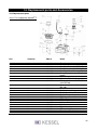
10. Replacement parts and Accessories
10.2.8 Pump Flange (Part Number 206-127)
Pos. Quantity
Order #
Name
1
2
3
4
5
6
7
206-126
206-160
206-134
071-106
206-139
206-135
206-052
Pump flange
Lower portion pump flange
Washers
Short fastening screws
Long fastening screws
Bolts
Threaded nut
1
1
14
2
12
14
12
11. Guarantee
1. In the case that a KESSEL product is defective, KESSEL has the option of repairing or replacing
the product. If the product remains defective after the second attempt to repair or replace the
product or it is economically unfeasible to repair or replace the product, the customer the has the
right to cancel the order / contract or reduce payment accordingly. KESSEL must be notified
immediately in writing of defects in a product. In the case that the defect is not visible or difficult to
detect, KESSEL must be notified immediately in writing of the defect as soon as it is discovered. If
the product is repaired or replaced, the newly repaired or replaced product shall receive a new
warranty identical to that which the original (defective) product was granted. The term defective
product refers only to the product or part needing repair or replacement and not necessarily to the
entire product or unit. KESSEL products are warranted for a period of 24 months. This warranty
period begins on the day the product is shipped from KESSEL to its customer. The warranty only
applies to newly manufactured products. Additional information can be found in section 377 and
378 of the HGB.
2. Wear and tear on a product will not be considered a defect. Problems with products resulting
from improper installation, handling or maintenance will also not be considered a defect.
01.01.2002
47
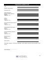
Important contacts / Info
Type
KESSEL Order Number
Production Date
Project description /
Building services supervisor
Address
Telephone / Fax
Planner
Address
Telephone / Fax
Contracted construction company
Address
Telephone / Fax
Contracted plumbing company
Address
Telephone / Fax
Contracted electrical company
Address
Telephone / Fax
System operator
Address
Telephone / Fax
Other remarks
The system operator, and those responsible, were present during the commissioning of this
system.
______________________________
Place and Date
48
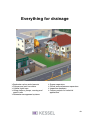
Everything for drainage
Backwater valves and cleanouts
Polymer and cast iron drains
Volatile liquid traps
Lifting stations, pumps, warning and
control units
Rainwater management systems
Grease separators
Oil/fuel and coalescence separators
Inspection chambers
Custom projects for industrial
applications
49