1
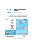
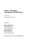
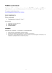
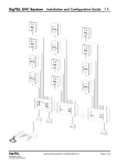
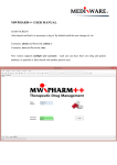
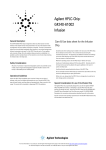
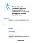
Agilent Nanoflow LC System for
Mass Spectrometry (MS)
G2229A
Quick Start Guide
In this guide
1. Stacking the System 2
2. Preparing the System 4
3. Operation - Tips and Hints 6
Part Information 8
Use this guide to help you install your Agilent Nanoflow LC System for MS.
This guide also provides valuable tips and hints for operation of the system.
Following these hints will ensure a successful run.
If you need to reorder parts please refer to the tables on the rear page.
Agilent Technologies
Stacking the System
1. Stacking
the System
Micro Well-Plate
Sampler (WPS)
G1377A
Nano Pump
G2226A
Micro Degasser
G1379A
Solvent Cabinet
5062-8581
Preparing the System
see page
4-5
2
StackingHow
thetoSystem
Proceed
Installation
Step
Unpack and install • Place the micro well-plate sampler on the bench
the WPS
• Remove the ST safety foam
• Connect the power cable
• Connect the corrugated waste tube to the seat adapter
and the solvent waste port from the leak plane
Unpack and install • Place the nanoflow pump on top of the WPS
the nanoflow
• Connect the CAN cable between the pump and the
pump
WPS
• Connect the power cable
• Connect the waste tube to the EMPV of the pump
Unpack and
install the micro
degasser
• Place the micro degasser on top of the pump
• Connect the power cable
• Connect the solvent tube G1322-67300 between the
outlet port of the degasser and the solvent selection
valve of the pump
• Place the solvent cabinet on top of the degasser
Unpack and
install the solvent • Place the bottles in the solvent cabinet
cabinet
• At the bottle head assembly G1311-60003 replace the
glass solvent inlet filter with a SST solvent inlet filter
1018-60025
• Connect the bottle head assembly to the inlet port of
the degasser
• Connect the tube from the peristaltic flush pump to the
solvent bottle in the solvent cabinet
Nanoflow LC System for MS - Quick Start
Stacking the System
bottles
bottle head assembly
Solvent Cabinet
A B C D
outlet ports
inlet ports
Micro Degasser
connecting tube
EMPV
A1
B1
solvent selection valve
A2
B2
Nanoflow Pump
peristaltic pump
waste tube
Micro Well-plate Sampler
to waste
Figure 1
Stacking Overview
solvent tubing (5m)
tube screw
ferrules with lock ring
solvent inlet filter (SST)
Figure 2
Bottle Head Assembly - Overview
Nanoflow LC System for MS - Quick Start
3
Preparing the System
2. Preparing
the System
Preparing
Solvent
Preparing
System
Installation
Howthe
to Proceed
Step
Prepare
solvent
• Prepare 0.1% formic acid in water for channel A
• Prepare 0.1% formic acid in ACN for channel B
• Prepare 15% methanol, 84% water, 01% formic acid for the
washing solvent of the WPS needle
Purge
• Turn ON the micro degasser and the pump
• Connect the handheld controller to the pump
Purging the
System
• Activate the purge mode by selecting: View>System>
Control>Nano Pump>Purge task at the handheld controller
• Set the flow to 2.5 ml/min and purge each channel
separately for 4 minutes.
• Switch to 50/50 A/B and purge for additional 4 minutes
Plumbing the
System
Connect the
capillaries
• Turn ON the micro well-plate sampler
• Connect capillary #1 (G1375-87322) (see Figure 3) between
flow sensor outlet and switching valve port 1.
• Connect capillary #6 (G1375-87323) to switching valve port 6.
• Replace the seat capillary # 4 with capillary G1375-87316
provided in the accessory kit
• Activate the Micro mode by selecting Setting>Nano Pump
> More>Micro Flow at the handheld controller
Operating tips
see page
6
4
• Set the flow to 4 µl/min, solvent composition 50/50 A/B.
To monitor the flow and pressure at the handheld controller
select Plot>Select>Nano Pump Pressure>More>Nano
Pump Flow>More. Make sure these stabilize at least for 10
minutes before making the next connection. Flow ripple
should be less than 15%. Flow and pressure plots should look
similar to Figure 4.
This procedure can take up to 60 minutes. If after this time the
pressure and the flow does not stabilize, there are probably
particles at the front end of the capillary. Backflush the tubing
to remove them.
Nanoflow LC System for MS - Quick Start
Preparing the System
Additional Installation Notes
The choice of mobile phase affects chromatography ionization efficiency and sample recovery. Typically
mobile phase solvents are water and acetonitrile, both with added organic acid.
• Formic acid causes less ion suppression than TFA
• TFA gives better ion paring / chromatography
• 0.1% formic acid in both water and acetonitrile are good general-purpose mobile phases for peptide analysis.
In the purge mode, the flow goes to waste rather than through the analytical system. You will not damage
the system by using the purge mode at 2.5 ml/min.
Purging the system is necessary if:
• It is being used for the first time.
• It was switched OFF overnight or longer.
• The vacuum degasser lines are empty.
• You have changed to a solvent that is immiscible with the previous solvent.
• Before connecting wash both ends with organic solvent and flush before connecting new capillaries to
other components
• Avoid air gaps between fittings.
• Do not overtighten, trap (in module doors), or bend capillaries with radius smaller than 4 cm.
• Always install and retighten without flow.
• Use pH lower that 9.
1
3
6
2
1
6
2
5
4
3
waste
Figure 3
5
4
Plumbing diagram (main pass)
Nanoflow LC System for MS - Quick Start
Figure 4
Stability of flow (top) and pressure (bottom)
5
3. Operation - Tips and Hints
3. Operation - Tips and Hints
System
• The system pressure of your newly installed
• For best results, use nanoflow rates from 0.1
system should be 40 - 50 bar under typical
µl/min to 1 µl/min.
conditions (300 nl/min of water with a 50 x
• In micro mode abnormally high column flow
0.075 mm, 3.5 µm column).
variations are an indication of small particles
• For stable flow, the system pressure must be
within the system.
higher than 20 bar at the pump outlet.
• When using buffer solutions, flush the system
• Check for plugged column capillaries if pressure
with water before switching it off.
increases more than 30 %
Capillaries
• Flush new capillaries before connecting to other • Replace capillaries if they are bend just after the
components. Wash both ends with organic
fitting or anywhere else with a diameter below
solvent and be sure the connection is dry before
4 cm.
connecting.
• Compare capillary pressure drop to that listed in
• Always install or retighten without flow.
Table 2. Replace capillary if you have more than
• Do not overtighten, trap (in module doors) or
30 % deviation.
bend with radius smaller than 4 cm.
• Inspect suspicious capillaries under
• Avoid gaps within fittings.
microscope. Replace those with milky surface.
• Use pH lower than 9.
Vials
The choice of glass versus plastic vials is
• Plastic capillary electrophoresis sample vials
sample-dependent. If you experience sample
(300 µl, 9301-0978) can work, but they are
recovery problems, you may want to try a different
opaque and tend to get an air bubble at the
type of vial.
bottom of the vial. Air bubbles can cause
Use the following hints as a guidance:
injection problems.
• Plastic vials are most commonly used.
• Conical polypropylene inserts (100 µl,
5182-05449) are less opaque and less prone to
• Polypropylene inserts and wide mouth vials are
persistent air bubbles at the bottom.
recommended.
6
Nanoflow LC System for MS - Quick Start
3. Operation - Tips and Hints
Pump/Degasser
• Use primary flow rate for low solvent
consumption.
• After changing solvents, purge each channel for
4 min.
• Check pressure drop of solvent filter in front of
the EMPV once a month.
• After sitting idle for a day or longer, flush each
channel for a few minutes.
• System backpressure should be higher than 20
bar.
• Irregular flow/pressure fluctuations indicate
partially blocked capillaries.
• Regular fluctuations indicate air within the high
pressure path.
• Rotate EMPV valve once while under flow to
remove dirt from the valve seat.
• Use clean solvent bottles and solvent.
• Never run without solvent inlet filters.
• Use glass bottled solvents.
• Filter solvents through 0.4 µm filters.
• The default settings (compressibility, flow
sensor calibration) are set for water in channel
A and acetonitrile in channel B.
Well-plate sampler (WPS)
• The recommended solvent for automatic
• Use bottom sensing when working with low
washing of the autosampler needle is 15%
sample volume.
methanol, 84,9% water, 0,1% formic acid.
• For direct injection use bypass mode. This
• Use needle wash.
leads to a sample transfer time between WPS
and column of 3-6 min (300 nl/min).
• Check alignment once a month.
•
Prime flush pump at least once a week for one
• Ensure comparable pressure drop in a mainpass
minute. Check that liquid is draining from the
and bypass once a week.
wash port while priming.
For more information on your Agilent Nanoflow System please check the Nano Pump User Manual
(G2226-90000), the Nano Pump Service Manual (G2226-90100), or the WPS Reference Manual (G1367-90002).
Nanoflow LC System for MS - Quick Start
7
Part Information
Table 1
Fittings and Ferrules
Fitting Type
Name
Description
Conditioning Part Number
A
Swagelok
1/16” SST fitting, front and back
ferrule
10/pk
5062-2418
B
Lite Touch
4/16” SST fitting
10/pk
5063-6593
Lite Touch
1/32” SST ferrule and lock ring
10/pk
5065-4423
C
Rheodyne
M4 PEEK fitting
6 fitt/2 plug
5065-4410
D
Finger Tight
Double winged nuts and
1/32” ferrules
10/pk
5065-4422
E
Lite touch detector M4, 1/16” SST fitting (male)
10/pk
5063-6593
Lite touch detector SST ferrule
10/pk
5063-6592
Lite touch detector PEEK sleeve
1/pk
5042-1396
Table 2
Capillaries and Fittings (for item numbers: see Figure 3)
Item Fitting Type
Material
Diameter
(µm)
Length
(mm)
Volume
(µl)
Pressure-drop for Part number
1µl/min H2O (bar)
1
PFS
25
350
0.172
6
PFS
100
200
1.570
G1375-87312
PFS
100
1100
8.639
G1375-87315
4
PFS
100
150
1.178
G1375-87317
4
PFS
75
150
0.663
G1375-87316
D/C
2
3
B/D
5
C/-
6
D/C
PFS
25
550
0.270
9
G1375-87323
6
D/C
PFS
25
350
0.172
6
G1375-87322
FS
25
8000
3.927
140
G2226-67300
Restriction Capillary
2000
G1375-87322
'
#(&'
'
#(&'
G2226-90001
Part Number: G2226-90001
Edition 02 / 2003
Printed in Germany
G1375-87326
© Agilent Technologies, Inc. 2003
Agilent Technologies, Deutschland GmbH
Hewlett-Packard-Strasse 8
76337 Waldbronn, Germany