1
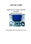
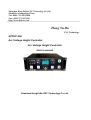
Shenzhen HongYuDa CNC Technology Co.,Ltd.
ShenZhen Guangdong China
Tel: 0086-755-26625800
Fax: 0086-755-2629960
http://www.hydcnc.com
Hong Yu Da
CNC Technology
XPTHC-200
Arc Voltage Height Controller
Arc Voltage Height Controller
User's manual
Shenzhen HongYuDa CNC Technology Co.,Ltd.
Shenzhen HongYuDa CNC Technology Co.,Ltd.
Preface
XPTHC-200 Arc Voltage Height Controller integrated the company's designers over 10
years experience in the Plasma Automatic Height Control design and applications, with
reference to the advantages and disadvantages of a large number of arc voltage home
and abroad. Its design not only inherits high-precision and high reliability of XPTHC-100,
also takes the user's requirement into account to make
the XPTHC-200 more flexible to
use, and easier to install, smaller, higher anti-interference performance,and a greater
range of applications.
Quality Assurance
In order to thank customers' support for the development of our company, HongYuDa
provides a high degree of quality of two years warranty for the new XPTHC-200 Arcvoltage controller. From the date of delivery, if the device can not work well due to the
failure of our product, our company offers free repair or replacement. This guarantee does
not apply to any damaged products caused by incorrect assembly and modification.
Through negotiation, users can freely choose free repair, replacement or adjust any
products within the scope of this guarantee.
Please note:
Document information:
HongYuDa will not announce and explain any modification in this document,
Please download the latest documents on http://www.hydcnc.com.
Technical Information:
Technical information and explanation involved in this document belongs to
HongYuDa, if you have any questions, please contact related technicians of
HongYuDa.
Use:
The company has the right to explain and guide all products sold, if there are any
failures or questions, please call us or write a letters any time.
HongYuDa CNC Technology CO.,LTD.. All rights reserved.
Shenzhen HongYuDa CNC Technology Co.,Ltd.
2
Shenzhen HongYuDa CNC Technology Co.,Ltd.
Catalogue
1. Brief Introduction ......................................................................................................................... 5
1.1. Product Model: .................................................................................................................. 5
1.2. Chinese Name: ................................................................................................................... 5
1.3. Application scope ............................................................................................................... 5
1.4. Structure (see Figure 1-1) ................................................................................................. 5
1.5. Installation .......................................................................................................................... 7
1.6. Working principle.............................................................................................................. 8
1.7. Basic functions and features ............................................................................................. 8
1.8 Arc voltage detection method: ........................................................................................... 9
2. Specifications ............................................................................................................................... 10
3. Working process ......................................................................................................................... 11
3.1. Working process with initial positioning ....................................................................... 11
3.2. Direct arc striking process: ............................................................................................. 11
4. Master controller of XPTHC-200.............................................................................................. 12
4.1. Control panel of XPTH-200 ............................................................................................ 12
4.2. Settings of XPTHC-200 ................................................................................................... 16
4.2.1. Settings of ascending speed .................................................................................. 16
4.2.2. Settings of descending speed ................................................................................ 17
4.2.3. Settings of low speed positioning ......................................................................... 17
4.2.4. Settings of response sensitivity of height turner ................................................ 17
4.2.5. Settings of motor drive current: .......................................................................... 19
4.2.6. Adjustment of motor plug braking ..................................................................... 19
4.3. Interfaces of XPTHC-200 controller.............................................................................. 20
4.3.1. Power port ............................................................................................................. 20
4.3.2. Cutting torch lift interface ................................................................................... 21
4.3.3. Interface connected to NC circuit ....................................................................... 22
4.3.4. Connecting to the interface of XPTHC-200-IHS ............................................... 23
5. XPTHC-200-IHS partial pressure, positioning and arc striking controller ......................... 23
5.1、
、Functions of XPTHC-200-IHS ..................................................................................... 23
5.2. Isolation partial pressure method .................................................................................. 23
5.3. Settings of initial positioning .......................................................................................... 24
5.3.1. Cutting torch protective cap positioning mode .................................................. 24
5.3.2. NPN normally open proximity switch positioning mode .................................. 25
5.4. Interface of XPTHC-200-IHS ......................................................................................... 25
5.4.1. Connected to XPTHC-200 ................................................................................... 25
5.4.2. Proximity switch positioning interface ............................................................... 26
5.4.3. Protective cap positioning interface .................................................................... 26
5.4.3. Arc voltage access port ......................................................................................... 28
5.4.4. Arc striking signal access interface ..................................................................... 29
6. Control wiring ............................................................................................................................. 30
3
Shenzhen HongYuDa CNC Technology Co.,Ltd.
6.1. XPTHC-200 system wiring diagram (Figure 6-1)......................................................... 30
6.2. Series connection of two proximity switches ................................................................. 31
6.3. Wiring method of control circuits of XPTHC-200 and HYD modules ....................... 31
7. Failure and maintenance............................................................................................................ 32
7.1. Troubleshoot .................................................................................................................... 32
7.2. Cancel elevating function of arc blowout cutting torch: .............................................. 34
7.3. Changes arc voltage settings of over voltage protection .............................................. 34
7.4 Some suggestions: ............................................................................................................. 34
4
Shenzhen HongYuDa CNC Technology Co.,Ltd.
1. Brief Introduction
1.1. Product Model:
XPTHC-200
1.2. Chinese Name:
Arc voltage height controller(弧压高度控制器)
1.3. Application scope
Cutting torch height control for plasma cutting machine with constant-current
characteristics or with a constant-current characteristics in a certain voltage range, it is
suitable for most imported
model or home products, it also applies to automatic height
control for automatic submerged arc welding and automatic argon arc welding.
Structure (see Figure 1-1)
1.4. Structure (see Figure 1-1)
XPTHC-200 torch height controller is comprised of following parts:
A. Master controller of XPTHC-200: Installed at a location convenient to operate。
B. XPTHC-200-IHS: positioning, arc striking, partial pressure controller. On the one
hand, the controller used to connect the arc voltage signal and arc striking signal of
plasma; on the other hand, it provides initial positioning.to protective cap contact
positioning interface and switch positioning interface. It can be installed at cutting torch lifter,
the entrance of towline, inside the CNC cabinet, but it is better to be installed at cutting torch lifter.
C. Control Cable: This product offers three cables to facilitate users:
1) 200101: connecting cable between XPTHC-200's master controller and
XPTHC-200-IHS, it has standard length of ten meters, eight meters and six meters are
for optional.
2) 200062: connecting cable between XPTHC-200's master controller and the NC, it
has standard length of six meters.
3) 200064: protective cap contact positioning cable with magnetic ring, it has
standard length of four meters, and it can be customized.
5
Shenzhen HongYuDa CNC Technology Co.,Ltd.
XPTHC-200 主控制器正面
XPTHC-200-IHS 控制器
POWER
AC24V
GND
Connected to the CNC
control circuit
开关定位接口
GND
保护帽
定位检
测信号
Connected to the cutting
torch motor and limit place
XPTHC-200 主控制器背面
Plasma start single
Plasma ARC-Voltage
XPTHC-200-IHS 控制器内部
Figure 1-1: Structure
6
Shenzhen HongYuDa CNC Technology Co.,Ltd.
1.5. Installation
XPTHC-200's master controller: Installed at a location convenient to operate.
Installation dimensions are as follows in Figure 1-2:
-200安装尺寸
Figure 1-2 XPTHC-200 installation dimensions
XPTHC-200-IHS: positioning, arc striking, partial pressure controller can be installed at
cutting torch lifter, the entrance of towline, inside the CNC cabinet, but it is better to be
installed at cutting torch lifter. Installation dimensions are as follows in Figure 1-3:
XPTHC-200-IHS定位、起弧、
分压控制盒安装尺寸
Figure 1-3 XPTHC-200-IHS installation dimensions
7
Shenzhen HongYuDa CNC Technology Co.,Ltd.
1.6. Working principle
The working principle of XPTHC-200 plasma arc voltage height controller is to use
characteristics of the basic constant-current of plasma current to achieve the height
control of cutting torch by detecting changes in plasma arc voltage to detect the change of
height of cutting torch in the process of plasma cutting.
1.7. Basic functions and features
Automatic initial positioning, two-speed positioning.
Detection method of switch positioning:
Proximity switches of XPTHC-200 are NPN normally-open proximity switches, under
the normal condition the switch is in contact state, proximity switches can also be
replaced with contact switch. In any state when the cutting torch touches the steel plate,,
the detection circuit acts and the torch will go to the original height, the height to the plate
can be set through SET-IHS potentiometer. When switches disengaged for a long time,
the cutting torch is always rising at the fastest speed, until the torch up to the maximum of
high limit, therefore, the switch has anti-collision protection function.
Detection method of protection cap collision:
The cutting torch cap touches the steel plate, and after the height turner received the
in positioning trigger signal, the cutting torch will be elevated to positioning height.
Two-speed positioning:
In the initial positioning process, after the height turner received the arc striking
command, it will descend at the fastest speed for two seconds and automatically switch to
slow descending, when the cutting torch touches steel plate to be cut and trigger
positioning signal, the height turner control the cutting torch elevating to the positioning height.
Through the two-speed positioning, it can improve positioning accuracy and extend the
life of cutting torch protective cap.
A. Separately set different operation speed
The elevating speed, descending speed and positioning speed of the system divide
into three gears, it can be set through simple band switching in circuit.
B. Automatic arc voltage height control
When the height turner is in automatic mode, If the actual arc voltage is less than set
arc voltage 30V, the height turner is in automatic mode.
C. Given arc voltage and actual arc voltage display control function:
Show the given arc voltage before arc striking, and show the actual arc voltage after
the arc striking perforation delay.
8
Shenzhen HongYuDa CNC Technology Co.,Ltd.
D. A variety of positioning functions:
The system can use protective cap contact positioning mode and proximity switches
positioning mode simultaneously. Usually both modes can be applied to water cutting.
When performing underwater cutting, it is better to use proximity switches positioning
mode. The advantages of using two-speed positioning in water cutting are: when cutting
rusty plate, the protective cap positioning may lead invalid positioning due to poor contact
with rust plate, when proximity switches positioning will act which can complete the
positioning effectively. It will be better if mated with our positioning fixture.
E. Cutting torch automatic elevating after completion:
When CNC cutting off the signal, the height turner will elevate the cutting torch
automatically for three seconds.
F. Arc voltage enable signal output:
By setting the panel on the SET-PIERE potentiometer to delay the output of the signal,
the signal is realized by testing whether there are arc voltage the output signal is
digital(binary).
G. Manual operation:
The functions, such as manual and automatic choose, manual elevating and
descending, testing of initial positioning and testing of arc striking, can be achieved on the
operation panel.
H. Automatic operation:
After the signals are sent by cutting program, the arc voltage height controller
automatically finished process of initial positioning---arc striking--arc voltage enable, NC
control the machine tools to cut after received arc voltage enable signal.
I. Anti-collision function:
In the automatic cutting process, if you set the arc voltage too low or because of
nozzle loss lead to cutting torch hit the plates, the height turner will automatically send
elevating signal to prevent cutting torch from pressing the steel plate and destroy the
cutting torch. It is better to be mated with our anti-collision fixture. It will not only send
elevating signal to height turner, but also send anti-collision signal to CNC to stop the
cutting. In non-cutting process, as long as the cutting torch hit the steel, it will
automatically raise an initial positioning height.
1.8 Arc voltage detection method:
Isolated partial pressure detection. Partial pressure ratio is 50:1.
9
Shenzhen HongYuDa CNC Technology Co.,Ltd.
2. Specifications
Working voltage: AC24V +10%, 50Hz/60Hz
Lifting motor: DC24V DC motor
Drive mode: PWM (Pulse width modulation)
Output current: 1A-4A, maximum 16A.
Output power: 100W, (according to user requirements, maximum to
300W)
Working temperature: -10 ∽ 60 ℃ increase in device
Initial positioning mode: Switching positioning
Protective cap contact positioning
Transmission: detecting arc voltage enable, perforation completion
output
Partial pressure ratio: 50:1
Accuracy: ±1V∽±
∽±3V,
related with user's motor starting voltage.
∽±
Outer dimensions: Length X Width X High: 240mmX200mmX80mm.
Cutting torch elevating speed: 1,000 m / min ∽ 4000 m / min (please
contact the supplier if exceed the speed)
Set arc voltage range: 30V∽
∽ 250V, it can be modified according to
different applications.
10
Shenzhen HongYuDa CNC Technology Co.,Ltd.
3. Working process
3.1. Working process with initial positioning
When arc striking signal connected to NC system is "arc striking signal with initial
positioning", the height turner will first perform initial positioning, when it is done, the
height turner automatically control arc striking of plasma, after the plasma produce
transferred arc, the height turner send arc voltage enable signal to NC system, and NC
system starts cutting operation. When the height turner send arc striking signal to plasma,
it delayed arc voltage to arc voltage controller system, after the arc voltage is pull in, if the
height turner itself is in automatic permit situation and NC system has sent the signal of
automatic elevating, the height turner is in automatic elevating state.
3.2. Direct arc striking process:
When the arc striking signal connected to NC system is "arc striking signal without initial
positioning", the height turner does not perform initial positioning and directly control the
arc striking of plasma. After the plasma produce transferred arc, the height turner send
arc voltage enable signal to NC system, and NC system starts cutting operation. When
the height turner send arc striking signal to plasma, it leads the arc voltage to arc voltage
controller system, after the arc voltage is pull in, if the height turner itself is in automatic
permit situation and NC system has sent the signal of automatic elevating, the height
turner is in automatic elevating state.
11
Shenzhen HongYuDa CNC Technology Co.,Ltd.
4. Master controller of XPTHC-200
4.1. Control panel of XPTH-200
Panel and size diagram shown in Figure 4-1:
ARC-Volt display
Status Indication
IHS height set
AUTO Change Button
Up Button
Piere dalay set
Arc-Volt set
IHS test Button
Down Button
ARCON test Button
Operation-Panel Size
图 4-1:
:操作面板
Figure 4-1: Control panel
Arc voltage display: The "SET" indicator light shows given arc voltage on control
panel, after arc striking and the setting of "Set Piere", it shows the actual arc voltage, then
the "Actual" light is on.
12
Shenzhen HongYuDa CNC Technology Co.,Ltd.
Arc voltage settings: According to the thickness, speed of cutting material and
parameters of the plasma to set the cutting arc voltage, the arc voltage can be shown on
arc voltage display before arc striking. The value of given arc voltage determines the
cutting height, if the given arc voltage increases, the cutting height also increases, in the
automatic cutting process, adjusts the given arc voltage to regulate cutting height.
Initial height setting potentiometer: Set the height of initial position, clockwise
rotation and height increase. The height of initial positioning achieved through the delayed
mode.
Initial height setting test button: Filmed button, press first when it is not cutting to perform
initial height setting test, it is mainly to check that the initial height setting is suitable or not.
Press the button or "UP" during the positioning process to cancel the positioning.
Set pierce: Set the time starting from plasma arc striking to CNC machine running,
only detected arc voltage to send arc voltage enable signal. Arc voltage enable signal is
switch output mode.
Automatically elevate button(Auto): filmed button.
To make height turner in automatic mode, the "INAUTO" indicator on the "AUTO" must
light, every time to press "AUTO" button, the "INAUTO" indicator will flip once. Only
"INAUTO" indicator lights and NC systems and height turner's interface send enable
signal, the height turner is in automatic status.
Arc striking test: filmed button:press the button and start the test of plasma arc
striking, release the button and the cutting torch will automatically elevate for three
seconds.
UP button (UP): filmed button. Manual UP button. Valid under any condition, up has
priority to down.
DOWN button (DOWN): filmed button. Manual DOWN button. Valid under any
condition, up has priority to down.
DOWN indicator light: light when descend.
PUMP indicator: it will be on when cutting torch touches steel plate or proximity switch
detaches to trigger positioning.
ARCON indicator: arc striking indicator, the indicator lights to show arc striking
operation has been carried out. Attention: when using "arc striking signal with initial
positioning" to conduct the cutting process, the indicator does not light in initial height
setting process, it must wait until the completion of positioning signal is detected, the
indicator will light.
TRANS indicator: when it is on which indicate that the system has detected the arc
voltage and has sent the arc voltage enable signal.
13
Shenzhen HongYuDa CNC Technology Co.,Ltd.
AUTO indicator: when it is on which indicate that height turner is in automatic mode, to
turn on the light, it should meet four conditions:
1. Control panel automatic signal have been loaded;
2. The automatic signal connected to NC system enable;
3. The controller detects arc voltage (arc voltage has been led);
4. The actual arc voltage does not exceed a given arc voltage of 30V. Note: The
over-voltage protection of height turner is 30V, it can be changed by adjustment of RP104
according to actual needs of customers, clockwise to reduce the voltage.
UP indicator: light when ascend.
INAUTO indicator: Default light in booting, through the "AUTO" button to control its status.
IHSTEST indicator: initial height settings indicator on control panel, only light in the initial
height settings process and will turn off after the positioning, it is invalid under in
automatic mode.
SET indicator: set arc voltage display, light when it is not working or without arc
voltage input.
ACTUAL indicator: The actual arc voltage display indicator, light when arc voltage
input.
Please attention:
A. The five indicator with silver circle on control panel light to indicate the height
turner is in automatic mode. If one of them does not light, the height turner is not in
automatic mode, increased device automatic increase in the state, panel 5 silver circle
lights are bright. You can determine the reasons of failure through the control panel.
B. There are six indicators on upper right corner of control panel, which show the
timing sequence of height turner from positioning>>>collision>>>arc striking>>>arc
feedback>>>automatic process, you can determine the reasons of failure through timing
sequence.
14
Shenzhen HongYuDa CNC Technology Co.,Ltd.
Figure 4-2 are three circuit boards in XPTHC-200 height turner:
Control panel
Arc voltage control panel
Motor driving board
Figure 4-2: XPTHC-200 internal circuit boards
15
Shenzhen HongYuDa CNC Technology Co.,Ltd.
4.2. Settings of XPTHC-200
4.2.1. Settings of ascending speed
XPTHC-200 sets manual and outer controlled ascending speed through two-band switch
SUP1 (on the arc voltage control panel), but ascending speed in automatic mode are not
related with the settings. It is only related with the settings of sensitivity. See figure 4-3
SDN1 descending speed setting switch
2# control logic chip
SUP1 ascending speed setting switch
SDL1 positioning speed setting switch
1# control logic chip
Figure 4-3: location of speed setting band switch
16
Shenzhen HongYuDa CNC Technology Co.,Ltd.
Ascending speed setting method of SUP1:
Ascending speed
High speed
1-4
2-3
ON
ON
Medium speed
ON
OFF
(default)
)
OFF
ON
Low speed
OFF
OFF
4.2.2. Settings of descending speed
XPTHC-200 sets manual and outer controlled descending speed through two-band
switch SDN1 (on the arc voltage control panel), but descending speed in automatic mode
are not related with the settings. It is only related with the settings of sensitivity. See figure
4-3
Ascending speed setting method of SDN1:
Descending speed
High speed
1-4
ON
2-3
ON
Medium speed
ON
OFF
(default)
)
OFF
ON
Low speed
OFF
OFF
4.2.3. Settings of low speed positioning
XPTHC-200 sets descending speed of low speed positioning through two-band switch
SDN1 (on the arc voltage control panel).
See figure 4-3
Descending speed of positioning setting method of SDL1:
Descending speed
1-4
2-3
High speed
ON
ON
Medium speed
ON
OFF
(default)
)
OFF
ON
Low speed
OFF
OFF
4.2.4. Settings of response sensitivity of height turner
The sensitivity of height turner is set up through the 4-band switch SEN (on the arc
voltage control panel). The level of sensitivity determines the precision of arc voltage
height turner, because the lifter's speed of cutting torch of each user are inconsistent, in
order to match the vast majority of users, XPTHC-200 designed a 5-speed precision
settings.
Location of sensitivity setting switch, see figure 4-4:
17
Shenzhen HongYuDa CNC Technology Co.,Ltd.
ensitivity setting switch
Figure 4-4: Sensitivity setting band switch
Sensitivity setting method of SEN:
Sensitivity
1-8
2-7
1
OFF
OFF
2
ON
3
3-6
4-5
Notes
OFF
OFF
1
OFF
OFF
OFF
highest,
ON
ON
OFF
OFF
5 for the lowest.
4
ON
ON
ON
OFF
5
ON
ON
ON
ON
for
the
Note of sensitivity settings:
Increasing sensitivity can get high cutting accuracy, but when the sensitivity is too high
which will produce oscillations to produce opposite effect, so it is essential to select the
appropriate sensitivity for normal use of height turner.
A. The device sensitivity settings is in the "5" position (the lowest).
B. Increase the sensitivity should set up based on the difference of set arc voltage and the
18
Shenzhen HongYuDa CNC Technology Co.,Ltd.
actual arc voltage, the deviation is in normal range of 1 ~ 3V, if the deviation exceeds 3V,
please increase sensitivity.
C. The increase in sensitivity should be progressively increased, do not put it to the
highest location.
D. When users determined the location, they can tell our company, we will set up it in
default.
4.2.5. Settings of motor drive current:
Motor drive current setting switch is SP2, installed in the motor drive board.
See figure 4-5
Current setting method:
Current
4A(4~16A)
1-8
OFF:
:PWM=9KHZ
3A
2A
ON:
:PWM=18KHZ
2-7
3-6
4-5
OFF
OFF
OFF
OFF
OFF
ON
OFF
ON
ON
1A
ON
ON
ON
Expanding output current of motor drive board can be achieved by increasing the size
of current-feedback resistor, to achieved paralleled 1Ω, 2W resistors with R6301 ~ R6303,
for each added resistor, the current increase 1.5A.
4.2.6. Adjustment of motor plug braking
XPTHC-200 height turner use motor plug braking to achieve fast braking. In this product,
to adjust the motor plug braking in an appropriate range by set the adjustable resistor
R6012 on driver board. See figure 4-5.
Plug braking adjustable potentiometer
Plug braking adjustment hole
Current regulation
Figure 4-5: Current regulation and plug braking adjustment
After the installation of internal circuit board of height turner, set the plug braking by a
19
Shenzhen HongYuDa CNC Technology Co.,Ltd.
screwdriver through the hole on arc voltage control panel. See figure 4-5.
Before delivery, plug braking of height turner has been adjusted, and need not to adjust
by users, but because transport, aging and device stability may cause braking deviation,
users can also adjust accordingly.
4.3. Interfaces of XPTHC-200 controller
To NC control circuit
Power switch
TO XPTHC-200-IHS
GND
AC24V POWER
To cutting torch motor and final limit
Figure 4-6 Controller Interface
4.3.1. Power port
XPTHC-200 uses AC24V power supply, input to height turner through Ф16 aviation
jack, the power of AC24V power supply is determined by motor power, and choose the
power of transformer according to the following formula. See figure 4-6:
Transformer power = motor power + 25
20
Shenzhen HongYuDa CNC Technology Co.,Ltd.
4.3.2. Cutting torch lift interface
Torch lift interface uses 7-pin aviation jack to connect with motor, aviation jack is
defined as follows in figure 4-7:
1
DC motor
2
3
Lower limit switch
4
Higher limit switch
Common limit port
5
6
SPACE
7
SPACE
7-pin aviation jack
Figure 4-7: Cutting torch lift interface circuit diagram
Ascending and descending limit interface diagram in Figure 4-8:
Higher limit
图 4-8:
:上限位、
上限位、下限位接口
Lower limit
Figure 4-8: Higher limit and lower limit interfaces
Note: Usually, the limit switch of XPTHC-200 uses normally closed contact. But it also
can change to normally open contacts by change the program logic according to users
requirements.
21
Shenzhen HongYuDa CNC Technology Co.,Ltd.
4.3.3. Interface connected to NC circuit
Through a female DB9 socket connected to CNC system. Pins definition are in figure 4-9
Figure 4-9 definition of the interface connected to NC system
Notes:
All signals connected to NC system are using isolation mode, with active low.
Arc striking completion signal (ARCTRANS1, ARCTRANS2) is a switch signal.
The cable supplied by our company, the cable number is 200062 with a standard length
of five meters.
Internal schematic diagram of XPTHC-200, see figure 4-10:
Figure 4-10: Schematic diagram connected to NC circuit
22
Shenzhen HongYuDa CNC Technology Co.,Ltd.
4.3.4. Connecting to the interface of XPTHC-200-IHS
The cable uses eight-core four pairs twisted shielded cable, the cable provided by our
company, number 200101, the standard length is ten meters, 8 meters and 6 meters for
option.
Figure 4-11: XPTHC-200 and XPTHC-200-IHS cables
5. XPTHC-200-IHS partial pressure, positioning and arc striking controller
5.1、
、Functions of XPTHC-200-IHS
XPTHC-200-IHS separates the signals of plasma arc voltage and arc striking with
strong interference from master controller in order to improve the system's anti-jamming
capability, the signals between them are using isolation connection mode, at the same
time, it tries to shorten the distance from cutting torch to IHS positioning controller, which
effectively avoid the interference of plasma system to master controller and NC system,
and improve stability of the system.
5.2. Isolation partial pressure method
Voltage division circuit conducts 50:1 non-isolated partial pressure according to
diagram shown in figure 5-1, then after 1:1 isolating process, it connects to height turner,
therefore, arc voltage be isolated has small interference to height turning.
23
Shenzhen HongYuDa CNC Technology Co.,Ltd.
50:1 分压器 50:1 voltage divider
Figure 5-1: Non-isolated partial pressure
In actual practice, the arc voltage after voltage division is delayed and connected to
control circuit.
Plasma using high-frequency arc, please extend pierce time to avoid the
high-frequency lead to height turner.
5.3. Settings of initial positioning
5.3.1. Cutting torch protective cap positioning mode
The initial positioning interface of XPTHC-200 realizes in XPTHC-200-IHS, it is needed to
set up XPTHC-200-IHS only when using proximity switches to position. See figure 5-2.
24
Shenzhen HongYuDa CNC Technology Co.,Ltd.
Connected to XPTHC-200 master controller
Band switch of SW2 protective cap positioning setting
GND
Proximity switch
positioning interface
Plasma arc
striking signal
Plasma
arc
voltage
signal, white to negative,
red to positive
Protective cap
positioning
detection signal
Figure 5-2
SW2 band switches must all be OFF only when using protective cap to position.
5.3.2. NPN normally open proximity switch positioning mode
SW2 must all be ON when using proximity switch positioning mode, then the protective
cap contact positioning is still valid.
5.4. Interface of XPTHC-200-IHS
5.4.1. Connected to XPTHC-200
Use cable numbered 200101 to connect the two controllers, the cable is supplied by our
25
Shenzhen HongYuDa CNC Technology Co.,Ltd.
company with the standard length of 10 meters, 8 meters and 6 meters for option. See
figure 5-3
1X2
2X1
Figure 5-3 (the same as Figure 4-11)
1
2
3
Blue: common power
Black: signal
Proximity switch
Brown: Power, +24V
3 芯航插 3-pin aviation jack
Figure 5-4:
5.4.2. Proximity switch positioning interface
Positioning port of proximity switch connected with a Ф16 3-pin aviation jack, labelled
"Switch IHS", pin is defined as follows in Figure 5-4:
Note: A 250mA self-recovery fuse is installed in power supply section of proximity switch
in the controller in order to prevent the switch from faulting, and damage power supply.
Working process: when the height turner received the arc striking signal sent by NC
system, the cutting torch descends immediately, when it touches steel plate, proximity
switch detaches the point, height turner receives the signal and controls the cutting torch
ascending to set height immediately (in ascending process, the proximity switch will
automatically reset), when positioning completed, height turner controls plasma arc
striking automatically. This method applies to all plasma initial positioning.
5.4.3. Protective cap positioning interface
The positioning mode requires that the protective cap is metal structure which can
conduct each other. The positioning cables is accessed in "SHIELD" of XPTHC-200-IHS.
26
Shenzhen HongYuDa CNC Technology Co.,Ltd.
For the Protection Cap of plasma is ceramic, it can install a metal ring to realize
protective cap positioning. Connection diagram as shown in Figure 5-5:
弧压正端
磁环
磁环
Figure 55-5 Schematic diagram of the protective cap positioning
Working process of protective cap positioning: when the height turner received the arc
striking signal sent by NC system, the cutting torch descends immediately, when it
touches steel plate, height turner receives positioning trigger signal and controls the
cutting torch ascending to set height immediately, when positioning completed, height
turner controls plasma arc striking automatically.
Notes of protective cap positioning:
A. Access to protective cap through "SHIELD" on controller.
B. GND column must be in good grounding, cross-section of grounding conductor is
27
Shenzhen HongYuDa CNC Technology Co.,Ltd.
larger than 4mm².
C. Do not need to access WORK from the material frame, which is different from
XPTHC-100.
D. The cable connected to the protective cap must be high-voltage cable, our company
offers a 4-meter-long high-voltage cable with a magnetic ring, if you have special
requirements, please contact HongYuDa.
5.4.3. Arc voltage access port
The arc voltage of plasma accesses at "PLASMA ARC-VOL" on the back of XPTHC-200-IHS,
see Figure 5-6.
弧压 Arc striking
Arc voltage negative terminal
Arc voltage positive terminal
Figure 5-6: Location of arc voltage interface
28
Shenzhen HongYuDa CNC Technology Co.,Ltd.
5.4.4. Arc striking signal access interface
The arc striking signal of plasma accesses to "PLASMA START" of controller.
Figure 5-7 (PLASMA START) position of the plasma arc striking wiring
The plasma arc striking signal is controlled by a 5A relay.
29
Shenzhen HongYuDa CNC Technology Co.,Ltd.
6. Control wiring
6.1. XPTHC-200 system wiring diagram (Figure 6-1)
CABLE:20006
Figure 6-1: XPTHC-200 wiring diagram
30
Shenzhen HongYuDa CNC Technology Co.,Ltd.
6.2. Series connection of two proximity switches
The series connection uses two proximity switches to position, as long as any one
proximity switch action, height turner will detect the signal.
Figure 6-2: Series connection of two proximity switches
6.3. Wiring method of control circuits of XPTHC-200 and HYD modules
Figure 6-3 Example of NC wiring
31
Shenzhen HongYuDa CNC Technology Co.,Ltd.
7. Failure and maintenance
7.1. Troubleshoot
No.
1
Fault
The
Reason
display
has
Solution
No +5 V voltage
Check +5V voltage VCC5
nothing, black
2
Motor does not run or Driver IR2110 damaged
Change IR2110
only in one direction.
Check drive voltage VCC4
Drive-level voltage is +15 V,
Fault.
D606∽D609 (IRPF250)
Over current protection
may damaged or machine seized.
3
When power on, the
The
cutting
always
upper limit of cutting torch
elevates. (NPN switch
does not installed in place.
positioning mode)
It is in open state.
gun
proximity
Proximity
switch
switch
at
is
damaged
Proximity switch installs in place.
Change
the
switch
(Detection
distance of 2mm, NPN normally
open type)
4
can not automatically
Proximity
arc striking after the
damaged, no return signal.
completion
Positioning time is set too
of
initial
positioning.
switch
is
Change proximity switch.
To set a longer positioning time.
short, there is no return
signal
5
Unstable arc voltage
1. Check the grounding.
control
2 Check whether there is leakage of cooling water in plasma
power.
3. It is too sensitive.
6
The machine start to
SET-PIERE
run but perforation is
short.
time
is
too
not completed
7
1. Make SET-PIERE time longer.
2. Use the arc feedback signal of
plasma itself.
The plasma start arc
Using EXARCON signal in
3. Make the NC delay time longer.
striking
arc striking, the NC delay
4. Electrical circuit fault.
before
completion
of
the
initial
time is too short.
positioning.
32
Shenzhen HongYuDa CNC Technology Co.,Ltd.
8
Cutting torch can not
1. Make sure the plasma power is in operation.
start arc striking.
2. Check initial positioning perforation height is correct.
3. Check wearing parts of cutting torch.
4. There are iron slag near electrode and nozzle results in short
circuit when using protective cap positioning.
9
Plasma arc of cutting
1. Check the working cable of plasma.
torch
2. Check accessories of cutting torch.
can
not
be
transferred
to
workpiece.
10
Before
the
end
of
perforation of cutting
torch,
cutting
3. Extends perforation time in NC system.
4. Make SET-PIERE time longer.
torch
moves.
11
NC started to move,
1. Increases "given arc voltage" settings.
cutting torch descends
2. Extends automatic load time in NC system.
immediately
3. Reduces the value of over voltage protection, (clockwise
toward
workpiece.
adjustment RP104 potentiometer)
4. Check the corner signals or automatic signal of NC system are
normal.
12
After the transfer and
Delay is too long, (before moving the machine, cutting torch stays
perforation the plasma
too long at the perforation place, plasma arc easy to go out, this
arc
is most likely to occur when cutting thin metal plates)
extinguished
immediately.
13
When
in
positioning,
1. IHS time is to short.
cutting torch does not
2. Sensor wire and protective cap being poor contact.
lift when touch steel
3. Circuit fault.
plate.
14
Cutting torch touches
Detection cables and protective cap are in poor contact in
plate
protective cap positioning.
and
still
descends, there is no
Proximity switch is damaged in proximity switch positioning.
arc striking action.
The sampling signal of height turner are open circuit or poor
contact.
33
Shenzhen HongYuDa CNC Technology Co.,Ltd.
15
In
automatic
cutting
mode,
torch
is
oscillating
and
Height turner sensitivity is too high, you can adjust SEN switch to
lower its sensitivity.
Circuit fault.
unstable.
16
In
automatic
mode,
height turner tracks too
Height turner sensitivity is too low, you can adjust SEN switch to
increase its sensitivity.
slow.
17
Arc stopped in cutting
Reason: This height turner detects arc voltage signal, after arc
process,
stopped the arc voltage can not come down immediately.
arc
voltage
enable signal continues
Solution: Use the arc feedback signal of plasma itself.
to output, the machine
does not stop.
7.2. Cancel elevating function of arc blowout cutting torch:
The function of cutting torch elevating: The lifting system will be seized if the limit
equipment does not install. If NC system has the function of automatic lifting control, it can
be cancel on master controller of height turner.
There are two ways to cancel the cutting torch elevating function:
1. Canceled R155 resistor on the master control board.
2. Canceled R116 resistor on the master control board.
7.3. Changes arc voltage settings of over voltage protection
The set arc voltage of over voltage protection is 30V, it can be changed by adjusting
PR104 on the circuit board: clockwise a circle, the value drops about 4V, otherwise the
value improves 4V. To prevent cutting gun from touching steel plate when cutting slotted
plate. For example: if the value is too hight, the cutting gun will be easy to touch the steel
plate at inlets and outlets, it can change the value by adjust RP104.
Concept: over voltage protection arc voltage definition: the difference between the actual
arc voltage and set arc voltage. If the sum of actual arc voltage of arc voltage height
turner with over voltage protection is large than set value, height turner will automatically
cancel the automatic elevating function.
Attention: The over voltage protection value can not be freely adjusted, if the value is too
low, automatic elevating function will not be automatically loaded during the cutting
process.
7.4 Some suggestions:
1. In the use of protective cap positioning, it is recommended users to install
anti-collision fixture and connect the protective cap positioning, so that in practice if the
protective cap does not touch well with cutting plates, the proximity switch positioning also
be effective at the same time, which is more help to protect the cutting torch. Two
34
Shenzhen HongYuDa CNC Technology Co.,Ltd.
anti-collision function of positioning are valid under the circumstances of installed two
positioning modes.
2. When using proximity switches positioning function, our company proposes to adopt a
number of proximity switches to position, wired as in Figure 6-2.
3. When CNC system you used can not receive arc striking enable signal, you should use
delay method to control NC operation. Namely, after NC system sends arc striking signal
to height turner, delay and enable NC to operate.
35