1
Foreword
Thank you for choosing POWTRAN PI130 Series Frequency Inverter. This
product made by POWTRAN is based on years of experience in professional production
and sale, and designed for variety of industrial machinery, fan and water pump drive
unit and IF heavy-duty grinding unit.
This manual provides user the relevant precautions on installation,operational
parameter setting, abnormal diagnosis, routine maintenance and safe use. In order to
ensure correct installation and operation of the frequency converter, please carefully
read this manual before installing it.
For any problem when using this product, please contact your local dealer
authorized by this company or directly contact this company, our professionals are
happy to serve you.
The end-users should hold this manual,and keep it well for future maintenance &
care,and other application occasions. For any problem within the warranty period,please
fill out the warranty card and fax it to the our authorized dealer.
The contents of this manual are subject to change without prior notice. To obtain
the latest information, please visit our website.
For more product information, please visit: http://www.powtran.com.
POWTRAN
July,2013
I
Table of Contents
Foreword ................................................................................................................ I
Table of Contents ...................................................................................................II
Chapter 1 Inspection and Safety Precautions ........................................................... 1
1-1. Inspection after unpacking.................................................................... 1
1-1-1. Instructions on nameplate............................................................. 1
1-1-2. Model designation ....................................................................... 1
1-2. Safety Precautions ................................................................................ 2
1-3. Precautions .......................................................................................... 4
1-4. Scope of applications............................................................................ 7
Chapter 2 Standard Specifications ........................................................................... 8
2-1. Technical Specifications ....................................................................... 8
2-2. Standard specifications ......................................................................... 9
2-3. Dimensions ........................................................................................ 12
2-3-1. PI130 Series .............................................................................. 13
2-3-2. Keyboard size diagram............................................................... 15
Chapter 3 Keyboard.............................................................................................. 16
3-1. Keyboarddescription .......................................................................... 16
3-2. Keyboard Indicators ........................................................................... 16
3-3. Description of operation panel keys .................................................... 17
3-4. Examples of parameter settings........................................................... 17
3-4-1. Password Settings ...................................................................... 19
3-4-2. Motor parameter auto tunning .................................................... 19
Chapter 4 Commissioning..................................................................................... 21
Chapter 5 Function parameter ............................................................................... 22
5-1. Menu grouping................................................................................... 22
5-1-1. d0 Group - Monitoring function.................................................. 23
5-1-2. F0 Group - Basic function .......................................................... 25
5-1-3. F1 Group - Input terminals ......................................................... 27
5-1-4. F2 Group - Output terminals....................................................... 29
II
5-1-5. F3 Group - Start and stop control ................................................ 30
5-1-6. F4 Group - V/F control............................................................... 31
5-1-7. F5 Group - Vector control group ................................................. 32
5-1-8. F6 Group - Keyboard and display ............................................... 32
5-1-9. F7 Group - Auxiliary function .................................................... 34
5-1-10. F8 Group - Fault and protection ................................................ 35
5-1-11. F9 Group - Communication parameter ...................................... 36
5-1-12. FA Group - Torque control........................................................ 38
5-1-13. Fb Group - Control optimization ............................................... 38
5-1-14. E0 Group - Wobbulate control .................................................. 39
5-1-15. E1 Group - Multi-speed control ................................................ 39
5-1-16. E2 Group - PID control ............................................................ 40
5-1-17. E3 Group - Virtual DI, Virtual DO ............................................ 41
5-1-18. b0 Group - Motor parameters.................................................... 43
5-1-19. y0 Group - Function code management ..................................... 44
5-1-20. y1 Group - Fault history search ................................................. 44
5-2. Function parameter description ........................................................... 46
5-2-1. dO Group - Monitoring function group ....................................... 46
5-2-2. F0 Group - Basic function group................................................. 47
5-2-3. F1 Gruop - Input terminals group ............................................... 53
5-2-4. F2 Group - Output terminals group ............................................. 57
5-2-5. F3 Group - Start and stop control group ...................................... 60
5-2-6. F4 Group - V/F control group ..................................................... 61
5-2-7. F5 Group - Vector control group ................................................. 64
5-2-8. F6 Group - Keyboard and display group ..................................... 65
5-2-9. F7 Group - Auxiliary function group ........................................... 67
5-2-10. F8 Group - Fault and protection group ...................................... 70
5-2-11. F9 Group - Communication parameter group ............................ 73
5-2-12. FA Group - Torque control group .............................................. 75
5-2-13. Fb Group - Control optimization group ..................................... 76
III
5-2-14. E0 Group - Wobbulate control group ........................................ 77
5-2-15. E1 Group - Multi-speed control group ...................................... 78
5-2-16. E2 Group - PID control group .................................................. 80
5-2-17. E3 Group - Virtual DI, virtual DO group ................................... 83
5-2-18. b0 Group - Motor parameter group ........................................... 87
5-2-19. y0 Group - Function code management..................................... 88
5-2-20. y1 Group - Fault history search group ....................................... 89
Chapter 6 EMC (Electromagnetic Compatibility) .................................................. 91
6-1. Definition .......................................................................................... 91
6-2. EMC Standard.................................................................................... 91
6-3. EMC Directive ................................................................................... 91
6-3-1. Harmonic Effect ........................................................................ 91
6-3-2. Electromagnetic Interference and Installation Precautions ........... 92
6-3-3. Remedies for the interferences from the surrounding
electromagnetic equipments to the inverter: ..................................................... 92
6-3-4. Remedies for the interferences from the inverter to the surrounding
electromagnetic equipments: ........................................................................... 92
6-3-5. Remedies for leakage current ..................................................... 93
6-3-6. Precautions on Installing EMC input filter at the input end of power
supply............................................................................................................. 94
Chapter 7 Troubleshooting.................................................................................... 95
7-1. Fault message and troubleshooting .................................................. 95
Chapter 8 Installation and Spare Circuit ................................................................ 98
8-1. Operating environment ....................................................................... 98
8-2. Installation Direction andSpace........................................................... 98
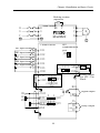
8-3. Wiring diagram .................................................................................. 98
8-4. Main circuit terminal ........................................................................ 100
8-4-1. PI130 main circuit terminal ...................................................... 100
8-4-2. Function Description of Terminals............................................ 100
8-5. Control circuit terminals ................................................................... 100
8-5-1. Description of control circuit terminals ..................................... 100
8-5-2. Arrangement of control circuit terminals ................................... 101
IV
8-6. Wiring Precautions: .......................................................................... 102
8-7. Spare Circuit .................................................................................... 102
Chapter 9 Maintenance and Repair ...................................................................... 104
9-1. Inspection and Maintenance.............................................................. 104
9-2. Parts for regular replacement ............................................................ 105
9-3. Storage............................................................................................. 105
9-4. Measuring and readings .................................................................... 106
Chapter 10 Warranty ........................................................................................... 107
Appendix I
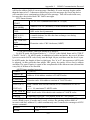
RS485 Communication Protocol................................................... 109
I-1. Introduction ...................................................................................... 109
I-2. Details .............................................................................................. 109
Warranty Card ................................................................................................ - 119 -
V
Chapter 1 Inspection and Safety Precautions
Chapter 1 Inspection and Safety Precautions
POWTRAN frequency inverters have been tested and inspected before leaving
factory. After purchasing, please check if its package is damaged due to careless
transportation, and if the specifications and model of the product are consistent with
your order requirements. For any problem, please contact your local authorized
POWTRAN dealer or directly contact this company.
1-1.Inspection after unpacking
※
※
Check if that packing container contains this unit, one manual and one warranty
card.
Check the nameplate on the side of the frequency inverter to ensure that the
product you have received is the right one you ordered.
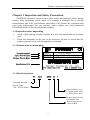
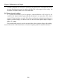
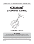
1-1-1.Instructions on nameplate
R
TYPE:
PI130 0R4G1
SOURCE: 1φ 220V 50-60Hz
OUTPUT: 0.4KW 2.5A 0.00-400.0Hz
ZPB1A0100001
POWTRAN TECHNOLOGY CO.,LTD.
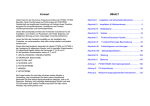
1-1-2.Model designation
Powtran Inverter
Series Code
130:PI130 series
Input Voltage Level
1: Single-phase 220V
2: Three-phase 220V
Product function code
G: Standard load
Rated output power
0R4: 0.4KW
1
Chapter 1 Inspection and Safety Precautions
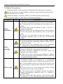
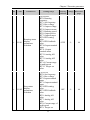
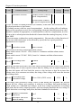
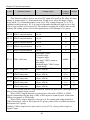
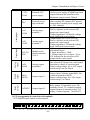
1-2.Safety Precautions
Safety precautions in this manual are divided into the following two categories:
Danger: the dangers caused by failure to perform required operation, may result in
serious body injury or even death;
Caution:the dangers caused by failure to perform required operation,may
result in moderate injury or minor injury, and equipment damage;
Process
Type
Explanation
★ When unpacking, if control system with water, parts
missed or component damaged are found, do not install!
★ If packing list does not match the real name, do not
install!
★ Gently carry with care,otherwise there is the risk of
Before
damage to equipment!
installation
Danger ★ Please do not use the damaged driver or the frequency
inverter with missed pieces,otherwise there is the risk of
injury!
★ Do not use your hand to touch the control system
components, otherwise there is the risk of electrostatic
damage!
★ Please install the unit on the metal or flame retardant
objects; away from combustible material. Failure to do so
may cause a fire!
Danger ★ Never twist the mounting bolts of the equipment
components, especially the bolt with the red mark!
When
★ Do not let the lead wires or screws fall into the driver.
installing
Otherwise which may cause damage to the driver!
★ Keep the driver installed in the place where less
vibration, avoid direct sunlight.
Note
★ When two or more converters are installed in a cabinet,
please pay attention to the installation location, ensure the
good heat dissipation effect.
★ Must comply with this manual's guidance,any
construction shall be performed by a professional
electrician, otherwise there would be the unexpected risk !
★ A circuit breaker must be set between the inverter and
the power supply to separate them, otherwise it may cause a
fire!
When wiring
★ Verify if power is a zero-energy status before wiring,
Danger otherwise there is a risk of electric shock!
★ The inverter shall be grounded correctly according to
standard specifications, otherwise there is a danger of
electrical shock!
★ Never connect the input power to the inverter output
terminals (U, V, W) . Note that the mark of the terminals,
2
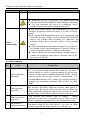
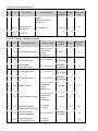
Chapter 1 Inspection and Safety Precautions
Process
Type
Note
Before
energizing
Danger
After
energizing
Danger
During
operation
Danger
Explanation
do not incorrectly connect wires! Otherwise which may
cause damage to the driver!
★ Ensure that the distribution line meets the regional safety
standards of EMC requirements. The diameter of used
wire shall refer to the recommendations of this manual.
Otherwise it may cause an accident!
★ When connecting to braking resistor,the braking resistor
must be connected to position between terminals (P, RB) of
the inverter
★ Please confirm whether the input power voltage is same
as the inverter rated voltage; wiring positions of power
input terminals (R,S,T) and output terminals (U,V,W) are
correct or not; and note that if there is a short circuit in the
peripheral circuit connected to driver,if the connected
lines are tight, otherwise it may cause damage to the
driver!
★ Do not need to perform withstand voltage test for any
part of the inverter,this product has been tested before
leaving factory. Otherwise it may cause an accident!
★ The inverter's cover plate must close before power on.
Otherwise it may cause an electric shock!
★ Wiring of all external accessories must comply with the
guidance of this manual,please correctly wiring in
accordance with the circuit connection methods described
in this manual. Otherwise it may cause an accident!
★ Do not open cover plate after energizing. Otherwise
there is a risk of electric shock!
★ Do not touch the driver and peripheral circuits with wet
hands. Otherwise there is a risk of electric shock!
★ Do not touch any input and output terminals of the
inverter. Otherwise there is a risk of electric shock!
★ The inverter automatically perform the safety testing for
the external strong electrical circuit in the early stages of
energizing, therefore never touch the driver terminals (U,
V, W) or motor terminals, otherwise there is a risk of
electric shock!
★ If you need to identify the parameters, please pay
attention to the danger of injury during motor rotation.
Otherwise it may cause an accident!
★ Please do not change the inverter manufacturer
parameters. Otherwise it may cause damage to this unit!
★ Do not touch the cooling fan and the discharge resistor
to feel the temperature. Otherwise it may cause burns!
★ Non-professional personnel is not allowed to detect
signal when operating. Doing so may cause personal
3
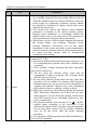
Chapter 1 Inspection and Safety Precautions
Process
Type
Note
When
maintaining
Danger
Explanation
injury or damage to this unit!
★ When the inverter is operating, you should avoid that
objects fall into this unit.Otherwise cause damage to this unit!
★ Do not start/stop the driver by switching on/off
contactor. Otherwise cause damage to this unit!
★ Do not perform repairs and maintenance for the live
electrical equipment. Otherwise there is a risk of electric
shock!
★ The repairs and maintenance task can be performed only
when the inverter voltage is lower than AC36V,generally
that is two minutes after powering off. Otherwise, the
residual charge from capacitor would cause personal
injury!
★ Non-well-trained professional personnel is not allowed
to perform repairs and maintenance of inverter. Doing so
may cause personal injury or damage to this unit!
★ After replacing the inverter,parameter settings must be
redone, all pluggable plugs can be operated only in the
case of powering off!
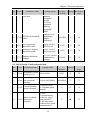
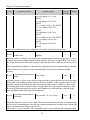
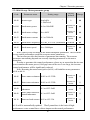
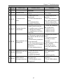
1-3.Precautions
No.
Type
1
Motor insulation
inspection
2
Motor thermal
protection
3
Run over power
frequency
4
Vibrations of
mechanical device
Explanation
Please perform motor insulation inspection for the first time
use, re-use after leaving unused for a long time as well as
regular check, in order to prevent damage to the inverter
because of the motor's winding insulation failure. Wiring
between motor and inverter shall be disconnected, it is
recommended that the 500V voltage type megger should be
adopted and insulation resistance shall be not less than
5MΩ.
If the rated capacity of the selected motor does not match
the inverter, especially when the inverter rated power is
greater than the motor rated power,be sure to adjust the
motor protection parameter values inside inverter or install
thermal relay in the front of motor for motor protection.
This inverter can provide (0Hz to 400Hz ) output
frequency If the user is required to run at 50Hz or more,
please consider the endurance of your mechanical devices.
Inverter output frequency may be encountered mechanical
resonance point of the load device, you can set jump
frequency parameter inside inverter to avoid the case.
4
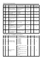
Chapter 1 Inspection and Safety Precautions
No.
Type
5
Motor heat and
noise
6
Output side with
piezoresistor or
capacitor for
improving power
factor
7
Contactor or
switch used in the
inverter
input/output
terminals
8
Use other than the
rated voltage
9
Never change 3phase input to 2phase input
10
Lightning surge
protection
11
High altitude and
derating
application
12
Special use
13
Precautions for
scrap disposal of
the inverter
14
About
adaptive motor
Explanation
The inverter output voltage is PWM wave that contains a
certain amount of harmonics, so the temperature rise,noise
and vibration of motor show a slight higher than frequency
power frequency operation.
The inverter output is PWM wave, if the piezoresistor for
lightning protection or the capacitor for improving power
factor is installed in the output side, which easily cause the
inverter instantaneous overcurrent or even cause damage to
the inverter. Please do not use.
If contactor is installed between power supply and
inverter,the contactor is not allowed to start/stop the
inverter. Necessarily need to use the contactor to control the
inverter start/stop, the interval should not be less than one
hour. Frequent charging and discharging may reduce the
service life of the inverter capacitor. If the contactor or
switch is equipped between output terminals and motor, the
inverter should be turned on/off without output status,
otherwise which easily lead to damage to the inverter
module.
PI series inverter is not suitable for use beyond the
allowable operating voltage described in this manual,which
easily cause damage to the parts inside inverter. If necessary,
please use the corresponding transformer to change voltage.
Never change PI series 3-phase inverter to 2-phase one for
application. Otherwise it will lead to malfunction or damage
to the inverter.
The series inverter is equipped with lightning overcurrent
protection device, so it has the ability of self-protection to
lightning induction. For the area where lightning is frequent,
user should also install the extra protection in the front of
the inverter.
When the inverter is used in areas over 1000m altitude,it is
required to reduce frequency because the thin air will
decrease the cooling effect of inverter. Please consult our
technician for details on the application.
If the user need to use methods other than the suggested
wiring diagram provided in this manual, such as common
DC bus, please consult our technician.
It may explode when electrolytic capacitors on the main
circuit and printed circuit board are burned. When burning
plastic parts, it may produce toxic gases.Please disposing as
industrial waste.
1) Standard adaptive motor shall be four-pole asynchronous
squirrel-cage induction motor. Apart from the said
motors, please select the inverter according to the motor
rated current.
5
Chapter 1 Inspection and Safety Precautions
No.
15
Type
Others
Explanation
2) The cooling fan and the rotor shaft for non-inverter motor
are coaxially connected, the fan cooling effect is reduced
when the rotational speed is reduced, therefore, when the
motor works in overheating occasions,a strong exhaust
fan should be retrofitted or replace non-inverter motor
with the inverter motor;
3) The inverter has built-in the adaptive motor standard
parameters, according to the actual situation, please
identify motor parameters or accordingly modify the
default values to try to meet the actual value,otherwise it
will operation affect and protection performance;
4) When short-circuit of cable or motor internal will activate
the inverter alarm, even bombing. Therefore, firstly
perform insulation short-circuit test for the initial
installation of the motor and cable, routine maintenance
often also need to perform such test. Note that the parts to
be tested and the inverter shall be disconnected
completely when testing.
1) Never connect the AC power to the inverter output
terminals (U, V, W) .
2) Properly fix and lock the panel before powering on, so as
to avoid hurting the personal safety due to internal poor
capacitors.
3) Never perform wiring, checking and other operations
after power is turned on.
4) Do not touch the internal circuit board and its
components in order to avoid the risk of electric shock
after this unit is powered,
5) Do not touch internal circuit board and any parts after
powering off and within five minutes after keyboard
indicator lamp goes out,you must use the instrument to
confirm that internal capacitor has been discharged
fully,otherwise there is a danger of electric shock.
6) Body static electricity will seriously damage the internal
MOS field-effect transistors, etc.,if there are not antistatic measures, do not touch the printed circuit board
and IGBT internal device with hand, otherwise it may
cause a malfunction.
7) The ground terminal of the inverter (E or )shall be
earthed firmly according to the provisions of the
National Electrical Safety and other relevant standards.
Do not shut down (power off) by pulling switch,and
only cut off the power until the motor stopping
operation.
8) It is required to add the optional input filter attachment so
as to meet CE standards
6
Chapter 1 Inspection and Safety Precautions
1-4.Scope of applications
※
※
※
This inverter only applies to typical industrial three-phase AC asynchronous motor.
This inverter can only be used in those occasions recognized by this company, an
unapproved use may result in fire, electric shock, explosion and other accidents.
If the inverter is used in such equipments (e.g: equipments for lifting
persons,aviation systems, safety equipment, etc.) and its malfunction may result in
personal injury or even death. In this case,please consult the manufacturer for your
application.
Only the well-trained personnel can be allowed to operate this unit,
please carefully read the instructions on safety, installation, operation and
maintenance before use. The safe operation of this unit depends on proper
transport, installation, operation and maintenance!
7
Chapter 2 Standard Specifications
Chapter 2 Standard Specifications
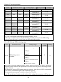
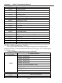
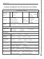
2-1.Technical Specifications
Inverter
model
PI1300R4G1
PI1300R7G1
PI1301R5G1
PI1300R4G2
PI1300R7G2
PI1301R5G2
Input
voltage
Single
phase
220V
±10%
Threephase
220V
±10%
Rated
output
Power
(KW)
Rated
input
Current
(A)
Rated output
current (A)
Adaptive
motor
Power (KW)
0.4
5.4
2.5
0.4
0.75
8.2
4.0
0.75
1.5
14.0
7.0
1.5
0.4
4.1
2.5
0.4
0.75
5.3
4.0
0.75
1.5
8.0
7.0
1.5
8
Chapter 2 Standard Specifications
Power
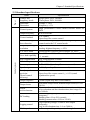
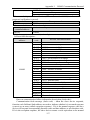
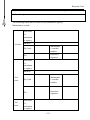
2-2.Standard specifications
Items
Voltage and
frequency levels
Allowable
fluctuation
Control system
Output frequency
Control method
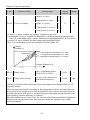
Automatic torque
boost function
Frequency setting
resolution
V/F curve mode
Over load capability
Slip compensation
Control system
Carrier Frequency
Start torque
Speed range
Steady-speed
precision
(Speed control
accuracy)
Torque response
Torque boost
Linear
ac/deceleration
DC braking
Jogging control
Multi-speed
Specifications
Single phase 220V, 50/60Hz
Three-phase 220V, 50/60Hz
Voltage: ± 10%
Frequency: ± 5%
High performance vector control inverter based on
DSP
0.00 to 400.0Hz
V/F control
Open-loop flux vector control
Realize low frequency (1Hz) and large output torque
control under the V/F control mode.
Digital: 0.01Hz
Analog: highest frequency × 0.2%
Linear,square root/m-th power,custom V/F curve
Rated Current 150% - 60 seconds, Rated Current 200%
- 1 seconds
Slip compensation available
1kHz to 15kHz
0.5Hz/150% (Open-loop flux vector control)
1:100 (Open-loop flux vector control)
Open-loop flux vector control: ≤ ± 0.5% (rated
synchronous speed)
≤40ms (Open-loop flux vector control)
Automatic torque boost; manual torque boost (0.1% to
30.0%)
Linear acceleration and deceleration mode; two kinds
of acceleration and deceleration time; time range 0.1s
to 3600.0s.
DC braking frequency: 0.00Hz to max.output
frequency;
Braking time: 0.0 to 50.0 seconds
Braking current value: 0.0% to 150.0%
Jog Frequency Range: 0.00Hz to max.output
frequency;
Jog Ac/deceleration time: 0.1s to 3600.0s
Achieve up to 16-speed operation through the control
9
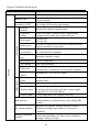
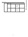
Chapter 2 Standard Specifications
Items
operation
Built-in PID
Automatic voltage
regulation (AVR)
Running
method
Frequency
setting
Input signal
Start signal
Multi-speed
Multi-stage
acceleration
Emergency
stop
Wobbulate run
Jog running
Output signal
Running
Fault reset
PID feedback
signal
Running
status
Fault output
Analog output
Output signal
Run function
DC current braking
Running command
channel
Specifications
terminal
Easy to realize closed-loop control system for the
process control.
Automatically maintain a constant output voltage when
the voltage of electricity grid changes
Keyboard/terminal/communication
Total 8 frequency stetting modes: digital,analog
voltage/current, multi-speed and serial port.
Forward run
Reverse run
At most 16-speed can be set (run by using the multifunction terminals or program)
At most 2-stage acceleration can be set (run by using
the multi-function terminals)
Interrupt controller output
Process control run
Slow speed running
When the protection function is active, you can
automatically or manually reset the fault condition.
Including DC 0 to 10V/0 to 20mA
Motor status display, forward, reverse, program
running status.
Relay contact capacity AC 250V/7A
1-way analog output, 9 signals can be selected such as
frequency,current,voltage and other, output signal
range (DC 0 to 10V/0 to 20mA) .
2-way output,there are 8 signals each way
Limit frequency,jump frequency,slip
compensation,reversal protection, auto-tuning, PID
control
Built-in PID regulates braking current to ensure
sufficient braking torque under no overcurrent
condition.
Three channels: operation panel,control terminals and
serial communication port. They can be switched
through a variety of ways.
10
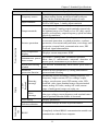
Chapter 2 Standard Specifications
Items
Frequency source
Input terminals
Output terminals
Communica
-tion
IGBT temperature
display
Displays current temperature IGBT
Less than 15 milliseconds: continuous operation.
Instantaneous powerMore than 15 milliseconds: automatic detection of
down restart
motor speed, instantaneous power-down restart.
Speed start tracking
The inverter automatically tracks motor speed after it
method
starts
Parameter
Protect inverter parameters by setting administrator
protection function
password and decoding
Monitoring objects including: running frequency, set
frequency, output current, DC bus voltage, output
Running
voltage, actual motor speed, PID setting value, PID
message
feedback value, input terminal status, output terminal
status, analog AI1 value, analog AI2 value,current
stage of multi-speed, torque set value, etc.
At most save 3 error messages,and the
Error
time,type,voltage,current,frequency and terminal status
message
can be queried when the failure is occurred.
LED display
Display parameters
Key lock and
It can lock all keys in order to prevent misuse.
function selection
LED
Keyboard
Display
Protection function
Inverter protection
Specifications
Total 8 frequency sources: digital,analog
voltage,analog current, multi-speed and serial port.
They can be switched through a variety of ways.
5 digital input terminals, compatible with the active
PNP or NPN input. 2 Analog input terminals
One digital output terminals (bipolar output) ; one relay
output terminal; 2 analog output terminals respectively
for optional range (0 to 20mA or 0 to 10V),they can be
used to set frequency, output frequency, speed and other
physical parameters.
Overvoltage protection, undervoltage protection,
overcurrent protection, overload protection, overheat
protection, overcurrent stall protection, overvoltage stall
protection, external fault, communication error, PID
feedback signal abnormalities.
RS485
Completely isolated RS485 communication module can
communicate with the host computer.
11
Chapter 2 Standard Specifications
Environment
Items
Environment
temperature
Storage temperature
Environment
humidity
Height and vibration
Application sites
Altitude
Product
Standard
Pollution degree
Product adopts
safety standards.
Product adopts
EMC standards.
Cooling method
Specifications
-10 ℃ to 40 ℃ (temperature at 40 ℃ to 50 ℃,
please derating for use)
-20 ℃ to 65 ℃
Less than 90% RH, non-condensing water droplets
Below 1000m, below 5.9m/s²(= 0.6g)
Indoor where no sunlight or corrosive, explosive gas
and water vapor, dust, flammable gas, oil mist, water
vapor, drip or salt, etc.
Below 1000m
2
IEC61800-5-1:2007
IEC61800-3:2005
Forced air cooling
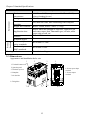
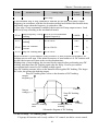
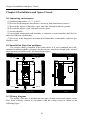
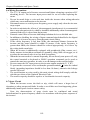
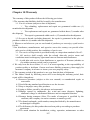
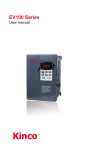
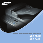
2-3.Dimensions
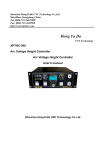
Appearance and installation holes size
1
2
3
4
1: Terminals bottom cover
2: Operation panel
4: Inverter power input
terminals
5: Inverter output
terminals
3: Terminals top cover
6: Nameplate
7: Air duct inlet
8: Fixing holes
6
7
12
8
5
Chapter 2 Standard Specifications
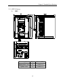
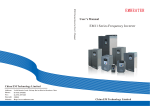
2-3-1.PI130 Series
1.
1M2
Power supply level
Type
Power (KW)
Single-phase 220V
G
0.4 to 0.75
3-phase 220V
G
0.4 to 0.75
13
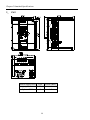
Chapter 2 Standard Specifications
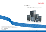
2. 1M3
Power supply level
Type
Power (KW)
Single-phase 220V
G
1.5
3-phase 220V
G
1.5
14
Chapter 2 Standard Specifications
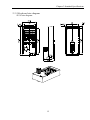
2-3-2.Keyboard size diagram
JP130 size diagram:
15
Chapter 3 Keyboard
Chapter 3 Keyboard
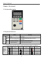
3-1.Keyboarddescription
Keyboard Schematic Diagram
3-2.Keyboard Indicators
Status Indicator
Indicator flag
FWD
Name
Forward running
lamp
Meaning
ON means that the inverter is forward
operating.
ON means that the inverter is reverse
operating.
REV
Reverse running lamp
Hz
Frequency Indicator
Frequency unit of the inverter
A
Current Indicator
Current unit of the inverter
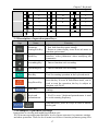
Correspondence that LED displays symbols and characters/digits is as follows:
Display
letters
Digital
display
area
Corresponding
letters
Display
letters
Corresponding
letters
Display
letters
Corresponding
letters
0
1
2
3
4
5
6
7
8
9
A
B
16
Chapter 3 Keyboard
C
d
E
F
H
I
L
N
n
o
P
r
S
t
U
T
.
-
y
3-3.Description of operation panel keys
Sign
Name
Parameter
Setting/Exit Key
Shift Key
Ascending Key
* Data or function code ascending
Decending Key
* Data or function code decending
Run Key
Used for running operation in the keyboard mode.
Stop/Reset Key
Enter Key
Keyboard
potentiometer
+
Function
* Enter top menu parameter change status
* Exit from function option change
* Return to status display menu from sub-menu or
function option menu
* Select circularly parameters under run or stop
interface; select parameters when modifying the
parameters.
* Press the key to stop running in running status;
press the key to reset in fault alarm status, can be
used to reset the operation, the key is subject to
function code F6.00.
* Enter into levels of menu screen,confirm
settings.
* F0.02 is set to 3,keyboard potentiometer is used
to set the running frequency.
Simultaneously press two keys to lock or unlock
the keypad.
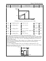
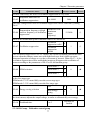
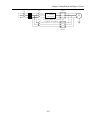
3-4.Examples of parameter settings
Instructions on viewing and modifying function code
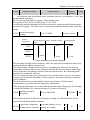
PI130 inverter operation panel has three levels of menu structure for parameter settings
and other operations. Three levels of menu is as follows: function parameter group (first
17
Chapter 3 Keyboard
level menu) → function code (second level menu) → function code settings (third level
menu) . The operation flow is shown in the figure.
Description: return to the second-level menu from the third-level menu by pressing PRG
key or ENTER key. The difference between the two keys : press ENTER to return the
second-level menu and save parameters setting before returning, and automatically
transfer to the next function code; press PRG to return directly to the second-level menu,
do not save parameters setting,and return to current function code .
Example 1 :restore factory default
50.00
PGR
y0
d0
ENTER
y0.00
ENTER
0
ENTER
50.00
1
Example 2 :change function code F0.01 from 50.00Hz to 40.00Hz
50.00
PGR
F0
d0
ENTER
F0.00
F0.01
PGR
F0
PGR
F0.02
ENTER
40.00
PGR
40.00
18
50.00
SHIFT
50.00
Chapter 3 Keyboard
In the third-level menu status, if the parameter has not blinking bit, it means that the
function code can not be modified, the possible causes include:
1) The function code can not be used to modify the parameters. Such as actual detection
parameters, run record parameters.
2) The function code can not be modified in the running status,can be modified only
after this unit is stopped.
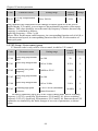
How to view status parameters
In stop or run status, operate SHIFT key to display a variety of status parameters
respectively. Parameter display selection depends on function code F6.01 (run
parameter) and F6.02 (stop parameter) .
In stop status, there are 10 run status, you can set to display or not display them: set
frequency, bus voltage, DI input status, DO output status, PID settings and PID
feedback, analog input AI1 voltage, analog input AI2 voltage,and switch and display the
selected parameter by pressing key orderly.
In run status, there are 16 run status, you can set to display or not display them:
running frequency, set frequency, bus voltage, output voltage, output current, output
power, output torque, DI input status, DO output status, analog input AI1 voltage,
analog input AI2 voltage, linear speed, PID settings and PID feedback,etc, their display
depends on function code F6.01, and switch and display the selected parameter by
pressing key orderly.
Inverter powers off and then powers on again, the displayed parameters are the
selected parameters before power-off.
3-4-1.Password Settings
The inverter has password protection, when Y0.01 is non-zero value, that is user
password, password protection will enter into force when you exit from function code
editing status, press the PRG key again,it will display "-----", you must enter correct
user password before entering regular menus, otherwise inaccessible.
To cancel the password protection function, firstly enter correct password to access
and then set Y0.01 to 0.
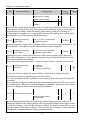
3-4-2.Motor parameter auto tunning
Select the operating mode of vector control, you must accurately input parameters
of the motor's nameplate before inverter operation, PI130 frequency inverter will match
the standard motor parameters according to the nameplate parameters; the vector control
method is highly dependent on motor parameters, in order to get good control
performance, the accurate parameters of the controlled motor must be required
Motor parameter auto tunning steps are as follows (Take asynchronous motor as an
example) :
Firstly select command source as keyboard control (F0.04=0). then input the
following parameters according to the actual motor parameters (selection is based on the
current motor) :
Motor
Parameters
Selection
b0.00: motor type selection b0.01: motor rated
Motor
power
19
Chapter 3 Keyboard
b0.02: motor rated voltage b0.03: motor rated
current
b0.04: motor rated frequency b0.05: motor rated
speed
If the motor can completely disengage its load, please select 1 (asynchronous
motor parameter comprehensive auto tunning) for b0.11, and then press the RUN key on
the keyboard panel:
If the motor can NOT completely disengage its load, please select 2 (asynchronous
motor parameter static auto tunning) for b0.11, and then press the RUN key on the
keyboard panel, the inverter will automatically calculate the motor‟s following
parameters:
Motor
Parameters
Selection
b0.06: Asynchronous motor stator resistance
b0.07: Asynchronous motor rotor resistance
b0.08: Asynchronous motor stator and rotor
Motor
inductance
b0.09: Asynchronous motor stator and rotor
mutual inductance
b0.10: Asynchronous motor no-load current
Complete motor parameter auto tunning
20
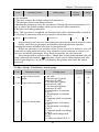
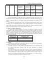
Chapter 4 Commissioning
Chapter 4 Commissioning
Commissioning
Select control manner
(setting F0.00)
F0.00=?
Open-loop flux
vector control
0
Configure correctly motor
parameters b0.01 to b0.05
group
V/F
Select appropriate
ac/deceleration time(setting
F0.05, F0.06)
control 2
Motor parameter auto
tunning fault(setting
b0.11)
Select run command
channel(setting F0.04)
Select appropriate frequency
command(setting F0.02)
Select appropriate
ac/deceleration time(setting
F0.05/F0.06)
Select motor start-up
mode(setting F3.00)
Start motor to run, observe
the phenomenon, if
abnormal, please refer to the
troubleshooting.
NO
Achieve the required
control effect?
YES
End
●
●
●
Firstly confirm that AC input power supply voltage shall be within inverter rated
input voltage range before connecting power supply to the inverter.
Connect power supply to the R, S and T terminals of the inverter.
Select the appropriate operation control method.
21
Chapter 5 Function parameter
Chapter 5 Function parameter
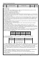
5-1.Menu grouping
PI130 inverter function parameters are grouped by function, there is d0 group, F0
group to Fb group, E0 group to E3 group, b0 group, y0 group to y1 group, L0 group, a
total of 21 groups. Each functional group includes several functional code.
F group and E group are the basic function parameters, d group is monitoring
function parameters and b group is motor parameters.
In order to more effectively carry out parameter protection, the inverter provides a
password protection of function code. y0.00 is used to set parameters protection
password, you can enter into parameter menu only after inputing correct password
under function parameters mode. Password protection is canceled when y0.00 is set to
00000.
L0 group is factory function parameters, users do not have access to the group of
parameters.
Function parameter table "Change", change properties (ie, whether to allow the
change or not and change conditions) and symbol description is as follows:
"★": indicates that the parameter value can not be changed when the inverter is
running;
"●": indicates that the parameter value is the actual measured value, can not be
changed;
"☆": indicates that the parameter value can be changed when the inverter is
running or stoped;
“▲”: "Factory parameters", prohibit the user to operate;
"-": indicates that the parameter factory default is none or the value is undefined.
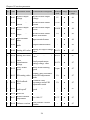
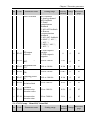
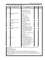
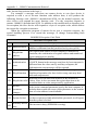
Code Parameter Group Name
Functional Description
Reference
page
Monitoring function
group
Monitoring frequency, current, etc
46
F0 Basic function group
Frequency setting, control mode,
acceleration and deceleration time
47
F1 Input terminals group
Analog and digital input functions
53
F2 Output terminals group
Analog and digital output functions
57
Start and stop control parameters
60
F4 V/F control group
V/F control parameters
61
F5 Vector control group
Vector control parameters
64
d0
F3
Start and stop control
group
22
Chapter 5 Function parameter
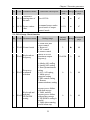
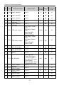
Code Parameter Group Name
To set key and display function
parameters
65
F7 Auxiliary function group
To set Jog, jump frequency and other
auxiliary function parameters
67
F8
Fault and protection
group
To set fault and protection parameters
70
F9
Communication
parameter group
To set MODBUS communication
function
73
To set parameters under torque control
mode
75
To set parameters of optimizing the
control performance
76
F6
Keyboard and display
group
Reference
page
Functional Description
FA Torque control group
Fb
Control optimization
group
E0 Wobbulate control group Wobbulate function parameters setting
E1
Multi-speed control
group
E2 PID control group
E3
Virtual DI, virtual DO
group
77
Multi-speed setting
78
To set Built-in PID parameters
80
Virtual IO setting
83
b0 Motor parameters group To set motor parameter
87
y0
Function code
management group
User password, initialization parameter
setting
88
y1
Fault history search
group
Information on current, former or first
two faults
89
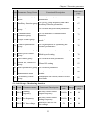
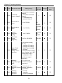
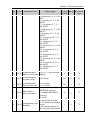
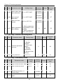
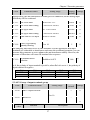
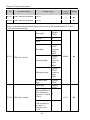
5-1-1.d0 Group - Monitoring function
No. Code
Parameter name
Running
frequency
Functional Description
Smallest
Reference
Change
unit
page
Inverter current actual
output frequency
0.01Hz
●
46
d0.01 Set frequency
Inverter current actual
setting frequency
0.01Hz
●
46
d0.02 DC bus voltage
Detected value for DC
bus voltage
1V
●
46
0.
d0.00
1.
2.
23
Chapter 5 Function parameter
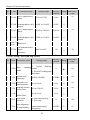
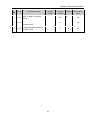
No. Code
Parameter name
Functional Description
Smallest
Reference
Change
unit
page
3.
d0.03
Inverter output
voltage
Inverter actual output
voltage
1V
●
46
4.
d0.04
Inverter output
current
Inverter actual output
current
0.1A
●
46
5.
d0.05
Inverter output
power
Inverter actual output
power
0.1kW
●
46
6.
d0.06
Inverter output
torque
Inverter actual output
torque percentage
1%
●
46
7.
d0.07
Input terminal
status
Input terminal status
-
●
46
8.
d0.08
Output terminal
status
Output terminal status
-
●
46
9.
d0.09 Analog AI1 value Analog AI1 input voltage
value
0.01V
●
47
10.
d0.10 Analog AI2 value Analog AI2 input voltage 0.01V
value
●
47
11.
Panel
d0.11 potentiometer
voltage
12.
d0.12
13.
d0.13 PID setting value
14.
d0.14
15.
d0.15
16.
d0.16 Reserved
17.
d0.17
18.
d0.18 Software version
Panel potentiometer
setting voltage value
0.01V
●
47
Motor actual running
speed
1rpm
●
47
Setting value percentage
under PID adjustment
mode
1%
●
47
PID feedback
value
Feedback value
percentage under PID
adjustment mode
1%
●
47
Current stage of
multi-speed
Current stage of multispeed
-
●
47
0.1℃
●
47
-
●
47
Motor actual
speed
Inverter module
temperature
0 to 100.0℃
DSP software version
number
24
Chapter 5 Function parameter
No. Code
Parameter name
Functional Description
19.
Cumulative
d0.19 running time of
this unit
0 to 65535h
20.
d0.20 Torque setting
value
Observe the set
command torque under
speed mode or torque
control mode
Smallest
Reference
Change
unit
page
1h
●
47
0.1%
●
47
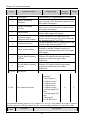
5-1-2.F0 Group - Basic function
No. Code Parameter name
Setting range
Factory
Reference
Change
default
page
21.
F0.00 Control mode
0: Open-loop flux
vector control
1: Reserved
2: V/F control
3: torque control
22.
F0.01 Keyboard set
frequency
0.00Hz to F0.08
(maximum output
frequency)
Frequency
F0.02 command
selection
0: keyboard setting
1: Analog AI1 setting
2: Analog AI2 setting
3: Panel potentiometer
setting
4: AI1+ AI2 setting
5: Multi-speed
operation setting
6: PID control setting
7: Remote
communications setting
0
☆
48
Keyboard and
terminal
F0.03
UP/DOWN
setting
0: Valid, and the
inverter power failure
with data storage
1: Valid, and the
inverter power failure
without data storage
2: UP/DOWN setting is
invalid
3: Valid when running,
invalid when stop
0
☆
49
23.
24.
25
2
★
48
50.00Hz
☆
48
Chapter 5 Function parameter
No. Code Parameter name
Setting range
25.
F0.04
Command
source channel
0: Keyboard command
channel
1: Terminal command
channel
2: Communication
command channel
26.
F0.05
Acceleration
time 1
27.
F0.06
Deceleration
time 1
28.
29.
Factory
Reference
Change
default
page
0
★
50
0.1 to 3600.0s
Depends
on
models
☆
50
0.1 to 3600.0s
Depends
on
models
☆
50
Carrier
F0.07 frequency
setting
1.0 to 15.0kHz
Depends
on
models
☆
51
Maximum
F0.08 output
frequency
10.00 to 400.00Hz
50.00Hz
★
51
30.
Upper limit
frequency
F0.09
setting source
selection
0: Keyboard setting
(F0.10)
1: Analog AI1 setting
2: Analog AI2 setting
3: Multi-speed setting
4: Remote
communications setting
Note: Option 1 to 4, the
setting value 100%
corresponds to the
maximum output
frequency
0
☆
51
31.
Running
F0.11 to F0.08
F0.10 frequency upper (maximum output
limit
frequency)
50.00Hz
☆
52
32.
Running
0.00Hz to F0.10
F0.11 frequency lower (running frequency
limit
upper limit)
0.00Hz
☆
52
33.
Running
F0.12 direction
selection
0
★
52
0: default
1: opposite
2: reverse prohibited
26
Chapter 5 Function parameter
No. Code Parameter name
34.
AVR function
F0.13
selection
Setting range
0: Invalid
1: full valid
2: only invalid during
deceleration
Factory
Reference
Change
default
page
1
☆
52
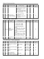
5-1-3.F1 Group - Input terminals
No. Code
Parameter name
Setting range
35.
F1.00
DI1 terminal
function selection
36.
F1.01
DI2 terminal
function selection
37.
F1.02
DI3 terminal
function selection
38.
F1.03
DI4 terminal
function selection
39.
F1.04
DI5 terminal
function selection
40.
F1.05 Reserved
0: No function
1: Forward run
2: Reverse run
3: Three-wire
operation control
4: Forward Jog
5: Reverse Jog
6: Frequency setting
increment (UP)
7: Frequency setting
decrement (DOWN)
8: Free stop
9: Fault reset
10: External fault
input
11: Frequency change
settings clear
12: Multi-speed
terminal 1
13: Multi-speed
terminal 2
14: Multi-speed
terminal 3
15: Multi-speed
terminal 4
16: Ac/deceleration
time selection
17: Control command
switch terminal
18: Ac/deceleration
prohibited
19: PID control pause
20: Wobbulate pause
(stops at the current
frequency)
21: Wobbulate reset
27
Factory
Reference
Change
default
page
1
★
53
2
★
53
8
★
53
9
★
53
4
★
53
Chapter 5 Function parameter
No. Code
Parameter name
Factory
Reference
Change
default
page
Setting range
(returns to the center
frequency)
22: Torque control
prohibited
23: Frequency change
settings temporarily
clear
24: Stop DC braking
25: Reserved
41.
Terminal control
F1.06
operation mode
0: Two-wire
control 1
1: Two-wire
control 2
2: Three-wire
control 1
3: Three-wire
control 2
type
type
type
0
★
55
0.50Hz/s
☆
56
56
type
42.
Change rate of
terminal
F1.07 UP/DOWN
frequency
increment
0.01 to 50.00Hz/s
43.
F1.08 AI1 lower limit
0.00V to F1.10
0.00V
☆
44.
F1.09
-100.0% to 100.0%
0.0%
☆
45.
F1.10 AI1 upper limit
F1.08 to 10.00V
10.00V
☆
46.
F1.11
AI1 upper limit
setting
-100.0% to 100.0%
100.0%
☆
47.
F1.12
Filter time of AI1
input
0.00s to 10.00s
0.10s
☆
48.
F1.13 AI2 lower limit
0.00V to F1.15
0.00V
☆
49.
F1.14
-100.0% to 100.0%
0.0%
☆
50.
F1.15 AI2 upper limit
F1.13 to 10.00V
10.00V
☆
57
51.
F1.16
-100.0% to 100.0%
100.0%
☆
57
52.
F1.17 Filter time of AI2
0.10s
☆
57
AI1 lower limit
setting
AI2 lower limit
setting
AI2 upper limit
setting
0.00s to 10.00s
28
56
56
56
56
57
57
Chapter 5 Function parameter
No. Code
Parameter name
Setting range
Factory
Reference
Change
default
page
input
53.
F1.18
Times of switching
1 to 10
quantity filtering
54.
F1.19
DI terminal mode
selection
0x000 to 0x1FF
5
☆
000
☆
57
57
5-1-4.F2 Group - Output terminals
No.
Code
55.
F2.00
56.
F2.01 Reserved
57.
F2.02 Reserved
58.
F2.03
59.
F2.04
Parameter name
MO1 output
selection
Relay output
selection
AO1 output
selection
Setting range
0: No output
1: Motor forward
running
2: Motor reverse
running
3: Fault output
4: Frequency level
detection FDT
output
5: Frequency
arrival
6: Zero speed
running
7: Upper limit
frequency arrival
8: Lower limit
frequency arrival
9 to 10: Reserved
0: Running
frequency
1: Set frequency
2: Output current
3: Output torque
4: Output power
5: Output voltage
6: Analog input
AI1 value
7: Analog input
AI2 value
8: Run speed
9 to 10: Reserved
29
Factory
Reference
Change
default
page
1
☆
57
1
☆
57
0
☆
58
Chapter 5 Function parameter
No.
Code
Parameter name
60.
F2.05
AO1 output lower
limit
61.
Lower limit
F2.06 corresponds to AO1 0.00V to 10.00V
output
62.
F2.07
63.
64.
65.
Setting range
Factory
Reference
Change
default
page
0.0%
☆
0.00V
☆
F2.05 to 100.0%
100.0%
☆
Upper limit
F2.08 corresponds to AO1 0.00V to 10.00V
output
10.00V
☆
00
☆
AO1 output upper
limit
F2.09 to
F2.10
0.0% to F2.07
59
59
59
59
Reserved
D0 terminal active
F2.14 status
selection
0x00 to 0x1F
59
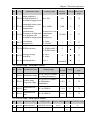
5-1-5.F3 Group - Start and stop control
No. Code Parameter name
Setting range
0: Directly startup
1:
Speed
tracking
running
restart
2: First DC braking and
then start
66.
F3.00
Start
mode
67.
F3.01
Startup start
frequency
0.00 to 10.00Hz
68.
F3.02
Hold time for
start frequency
69.
F3.03
70.
Factory
Reference
Change
default
page
0
★
60
0.50Hz
☆
60
0.0 to 50.0s
0.0 s
☆
60
Braking current
before start
0.0 to 150.0%
0.0%
☆
F3.04
Braking time
before start
0.0 to 50.0s
0.0 s
☆
71.
F3.05
Stop mode
selection
0: Deceleration stop
1: Free stop
0
☆
60
72.
F3.06
Start frequency
of stop braking
0.00 to F0.08
(maximum output
frequency)
0.00Hz
☆
61
30
60
60
Chapter 5 Function parameter
No. Code
Parameter name
73.
F3.07
Waiting time of
stop braking
74.
F3.08
75.
F3.09
Setting range
Factory
Reference
Change
default
page
0.0 s
☆
Stop DC braking
0.0 to 150.0%
current
0.0%
☆
Stop DC braking
0.0 to 50.0s
time
0.0 s
☆
0.0 to 50.0s
61
61
61
5-1-6.F4 Group - V/F control
No. Code
Parameter name
Setting range
Factory
Reference
Change
default
page
76.
F4.00 V/F curve setting
0: linear V/F curve
1: multi-point V/F
curve
2: square V/F curve
3:1.75th power V/F
curve
4:1.25th power V/F
curve
77.
F4.01 Torque boost
0.0%: automatic torque
boost
0.1% to 30.0%
0.0%
☆
62
78.
F4.02
Torque boost cutoff
0.0% to 50.0% (relative
to rated frequency of
motor)
20.0%
★
62
79.
F4.03
V/F frequency
point 1
0.00Hz to F4.05
0.00Hz
★
63
80.
F4.04
V/F voltage point
0.0% to 100.0%
1
0.0%
★
63
81.
F4.05
V/F frequency
point 2
F4.03 to F4.07
0.00Hz
★
63
82.
F4.06
V/F voltage point
2
0.0% to 100.0%
0.0%
★
63
83.
F4.07
V/F frequency
point 3
0.00Hz
★
63
84.
F4.08
V/F voltage point
0.0% to 100.0%
3
0.0%
★
63
F4.05 to b0.04 (rated
motor frequency)
31
0
★
62
Chapter 5 Function parameter
No. Code
85.
Parameter name
V/F slip
F4.09 compensation
limit
Setting range
0.0 to 200.0%
Factory
Reference
Change
default
page
0.0%
☆
64
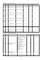
5-1-7.F5 Group - Vector control group
No. Code
Parameter name
Setting range
86.
F5.00
Speed loop
0 to 100
proportional gain 1
87.
F5.01
88.
Factory
Reference
Change
default
page
20
☆
64
Speed loop integral
0.01 to 10.00s
time 1
0.50 s
☆
64
F5.02
Switching low
point frequency
5.00Hz
☆
64
89.
F5.03
Speed loop
0 to 100
proportional gain 2
15
☆
64
90.
F5.04
Speed loop integral
0.01 to 10.00s
time 2
1.00
☆
64
91.
F5.05
Switching high
point frequency
10.00Hz
☆
64
92.
VC slip
F5.06 compensation
coefficient
50 to 200.0% (rated
inverter current)
100%
☆
65
93.
F5.07
0.0 to 200%
150%
☆
65
Torque upper limit
setting
0.00Hz to F5.05
F5.02 to F0.08
(maximum output
frequency)
5-1-8.F6 Group - Keyboard and display
No.
94.
Code
Parameters
STOP/RST key
F6.00 stop function
selection
Setting range
0: only active to panel
control
1: Valid for both panel
control and terminal
control
2: Valid for both panel
control and
communication control
3: Valid for all control
modes
32
Factory
Reference
Change
default
page
0
☆
65
Chapter 5 Function parameter
No.
95.
96.
Code
Parameters
Setting range
Factory
Reference
Change
default
page
Running status
display
F6.01
parameters
selection
0 to 0xFFFF
BIT0: Running
frequency
BIT1: Set frequency
BIT2: Bus voltage
BIT3: Output voltage
BIT4: Output current
BIT5: Running speed
BIT6: Output power
BIT7: Output torque
BIT8: PID setting
value
BIT9: PID feedback
value
BIT10: Input terminal
status
BIT11: Output
terminal status
BIT12: Analog AI1
value
BIT13: Analog AI2
value
BIT14: Current stage
of multi-speed
BIT15: Torque set
value.
03FF
☆
66
Stop status
display
F6.02
parameters
selection
1 to 0x3FF
BIT0: Set frequency
BIT1: Bus voltage
BIT2: Input terminal
status
BIT3: Output terminal
status
BIT4: PID setting
value
BIT5: PID feedback
value
BIT6: Analog AI1
value
BIT7: Analog AI2
value
BIT8: Current stage of
multi-speed
BIT9: Torque set
0FF
☆
66
33
Chapter 5 Function parameter
No.
Code
Parameters
Setting range
Factory
Reference
Change
default
page
value.
BIT10 to BIT15:
Reserved
97.
F6.03
Speed display
coefficient
98.
F6.04 to
F6.07
Reserved
0.1 to 999.9%
100.0%
☆
66
5-1-9.F7 Group - Auxiliary function
No. Code
Parameter name
Setting range
Factory
Reference
Change
default
page
0.00 to F0.08
(maximum
output
frequency)
5.00Hz
☆
67
99.
F7.00 Jog running frequency
100.
F7.01
Jog running
acceleration time
0.1 to 3600.0s
Depends
on models
☆
67
101.
F7.02
Jog running
deceleration time
0.1 to 3600.0s
Depends
on models
☆
67
102.
F7.03 Acceleration time 2
0.1 to 3600.0s
Depends
on models
☆
67
103.
F7.04 Deceleration time 2
0.1 to 3600.0s
Depends
on models
☆
67
104.
F7.05 Jump frequency
0.00 to F0.08
(maximum
output
frequency)
0.00Hz
☆
67
105.
F7.06 Jump frequency range
0.00 to F0.08
(maximum
output
frequency)
0.00Hz
☆
67
106.
Jump frequency
0: Invalid
F7.07 availability during
1: Valid
ac/deceleration process
0
☆
68
107.
F7.08
Depends
on models
☆
68
108.
F7.09 Power terminals
running protection
0
☆
69
Forward/reverse
rotation deadband
0.0 to 3600.0s
0: Power
terminals
34
Chapter 5 Function parameter
No. Code
Parameter name
selection
Setting range
Factory
Reference
Change
default
page
running
command
Invalid
1: Power
terminals
running
command
Valid
0.00 to F0.08
(maximum
output
frequency)
50.00Hz
☆
69
109.
FDT level detection
F7.10
value
110.
F7.11
FDT hysteresis
detection value
0.0 to 100.0%
(FDT level)
5.0%
☆
69
111.
F7.12
Frequency reaches
detection width
0.0 to 100.0%
(Set frequency)
0.0%
☆
70
112.
F7.13
Braking threshold
voltage
115.0 to 140.0%
(standard bus
voltage)
120.0%
☆
70
Factory
default
Change
Reference
page
160%
☆
70
0.00 to 100.00Hz/s
10.00Hz/s
☆
71
0: Always valid
1: Constant speed
invalid
0
☆
71
0: OFF
1: normal motor
(with low speed
compensation)
2: inverter motor
(without low speed
compensation)
2
★
71
5-1-10.F8 Group - Fault and protection
No. Code
Parameter name
Automatic current
100 to 200%
limiting level
113.
F8.00
114.
Frequency fall
F8.01 rate at current
limiting
115.
F8.02
116.
Setting range
Current limiting
action selection
Motor overload
F8.03 protection
selection
35
Chapter 5 Function parameter
No. Code
Parameter name
Setting range
Factory
default
Change
Reference
page
100.0%
☆
72
0
☆
72
115%
☆
72
0
☆
72
1.0 s
☆
72
80.0%
☆
73
0.00Hz/s
☆
73
117.
F8.04
20.0% to 120.0%
Motor overload
(rated motor
protection current
current)
118.
F8.05
Overvoltage stall
protection
119.
F8.06
Overvoltage stall 110 to 150% (220V
protection voltage series)
120.
Number of
F8.07 automatic fault
reset
0 to 3
121.
Automatic fault
F8.08 reset interval
setting
0.1 to 100.0s
122.
Descending
70.0 to 110.0%
frequency point of
F8.09
(standard bus
momentary power
voltage)
failure
123.
0.00Hz/s to F0.08
Frequency fall
F8.10 rate at momentary (maximum output
frequency)
power failure
0: Disable
1: Enable
5-1-11.F9 Group - Communication parameter
No. Code
124.
125.
F9.00
F9.01
Parameter name
Setting range
Factory
Reference
Change
default
page
Communication
baud rate setting
0: 1200bps
1: 2400bps
2: 4800bps
3: 9600bps
4: 19200bps
5: 38400bps
3
☆
73
Data bits parity
settings
0: no parity (N, 8, 1) for
RTU
1: even parity (E, 8, 1)
for RTU
2: odd parity (O, 8, 1) for
RTU
3: no parity (N, 8, 2) for
RTU
4: even parity (E, 8, 2)
for RTU
1
☆
73
36
Chapter 5 Function parameter
No. Code
Parameter name
Setting range
Factory
Reference
Change
default
page
5: odd parity (O, 8, 2) for
RTU
6: no parity (N, 7, 1) for
ASCII
7: even parity (E, 7, 1)
for ASCII
8: odd parity (O, 7, 1) for
ASCII
9: no parity (N, 7, 2) for
ASCII
10: even parity (E, 7, 2)
for ASCII
11: odd parity (O, 7, 2)
for ASCII
12: no parity (N, 8, 1) for
ASCII
13: even parity (E, 8, 1)
for ASCII
14: odd parity (O, 8, 1)
for ASCII
15: no parity (N, 8, 2) for
ASCII
16: even parity (E, 8, 2)
for ASCII
17: odd parity (O, 8, 2)
for ASCII
126.
F9.02
Communication
1 to 247, 0 for broadcast
address of this unit address
127.
F9.03
Communication
response delay
128.
F9.04
1
☆
74
0 to 200ms
5ms
☆
74
Communication
timeout fault time
0.0 (Invalid);
0.1 to 100.0s
0.0 s
☆
74
Data transfer
format selection
0: non-standard
MODBUS protocol
1: standard MODBUS
protocol
2: ASCII
0
☆
75
1
☆
75
129.
F9.05
130.
0: Alarm and free stop
1: No alarm and continue
Transmission error
F9.06
to run
handling
2: No alarm and stop at
the selected mode (under
37
Chapter 5 Function parameter
No. Code
Parameter name
Factory
Reference
Change
default
page
Setting range
communication control
mode only)
3: No alarm and stop at
the selected mode (under
all control modes)
131.
Transmission
F9.07
response handling
0: Write operations
responded
1: Write operations not
responded
5-1-12.FA Group - Torque control
Parameter
No. Code
Setting range
name
132.
Torque
FA.00 setting mode
selection
133.
FA.01
0
75
Factory
Reference
Change
default
page
0: Keyboard setting (FA.01)
1: Analog AI1 setting
2: Analog AI2 setting
3: Panel potentiometer
setting
4: Analog AI1+AI2 setting
5: Multi-segment torque
setting
6: Remote communications
setting
Note: Option 1 to 6, 100%
relative to two times of the
rated current of inverter
Keyboard set -200.0% to 200.0% (rated
torque
current of inverter)
☆
0
☆
75
50.0%
☆
76
Change
Reference
page
5-1-13.Fb Group - Control optimization
No. Code
Parameter name
Setting range
Factory
default
Depends ★
on models
76
Software undervoltage
0 to 500V
point
Depends ★
on models
76
Software overvoltage
point
Depends ★
on models
76
134.
Fb.00
Software overcurrent
point
135.
Fb.01
136.
Fb.02
137.
Low-frequency
Fb.03 threshold point of
0 to 500
oscillation suppression
4 to 2000A
300 to 800V
38
5
☆
76
Chapter 5 Function parameter
No. Code
Parameter name
Setting range
Factory
default
Change
Reference
page
138.
High-frequency
Fb.04 threshold point of
0 to 500
oscillation suppression
100
☆
76
139.
Amplitude limit value
Fb.05 of oscillation
suppression
0 to 10000
5000
☆
77
140.
Demarcation
frequency of high and
Fb.06
low frequency of
oscillation suppression
0.00Hz to F0.08
(maximum
output
frequency)
12.50Hz
☆
77
141.
Fb.07
0: valid
1: invalid
1
☆
77
142.
Fb.08 PWM selection
0: PWM mode 1
1: PWM mode 2
2: PWM mode 3
0
★
77
143.
Fb.09
0: OFF
1. Auto
0
★
77
144.
Fb.10 Deadband time
Depends
on models
★
77
Oscillation
suppression
Energy-saving
selection
2 to 5
5-1-14.E0 Group - Wobbulate control
No. Code
Parameter name
Factory
Reference
Change
default
page
Setting range
0.0 to 100.0% (relative
to setting frequency)
0.0%
☆
78
Sudden jump
frequency range
0.0 to 50.0% (relative
to Wobbulate
amplitude)
0.0%
☆
78
E0.02
Wobbulate rise
time
0.1 to 3600.0s
5.0 s
☆
78
E0.03
Wobbulate fall
time
0.1 to 3600.0s
5.0 s
☆
78
145.
E0.00 Wobbulate range
146.
E0.01
147.
148.
5-1-15.E1 Group - Multi-speed control
No. Code Parameter name Setting range Factory defaultChange Reference page
149.
E1.00 Multi-speed 0
-100.0 to 100.0%
0.0%
☆
78
150.
E1.01 Multi-speed 1
-100.0 to 100.0%
0.0%
☆
78
39
Chapter 5 Function parameter
No. Code Parameter name
Setting range Factory defaultChange Reference page
151.
E1.02 Multi-speed 2
-100.0 to 100.0%
0.0%
☆
78
152.
E1.03 Multi-speed 3
-100.0 to 100.0%
0.0%
☆
79
153.
E1.04 Multi-speed 4
-100.0 to 100.0%
0.0%
☆
79
154.
E1.05 Multi-speed 5
-100.0 to 100.0%
0.0%
☆
79
155.
E1.06 Multi-speed 6
-100.0 to 100.0%
0.0%
☆
79
156.
E1.07 Multi-speed 7
-100.0 to 100.0%
0.0%
☆
79
157.
E1.08 Multi-speed 8
-100.0 to 100.0%
0.0%
☆
79
158.
E1.09 Multi-speed 9
-100.0 to 100.0%
0.0%
☆
79
159.
E1.10 Multi-speed 10
-100.0 to 100.0%
0.0%
☆
79
160.
E1.11 Multi-speed 11
-100.0 to 100.0%
0.0%
☆
79
161.
E1.12 Multi-speed 12
-100.0 to 100.0%
0.0%
☆
79
162.
E1.13 Multi-speed 13
-100.0 to 100.0%
0.0%
☆
79
163.
E1.14 Multi-speed 14
-100.0 to 100.0%
0.0%
☆
79
164.
E1.15 Multi-speed 15
-100.0 to 100.0%
0.0%
☆
79
5-1-16.E2 Group - PID control
No. Code
Parameter name
Setting range
165.
E2.00
PID setting source
selection
0: Keyboard setting
(E2.01)
1: Analog channel
AI1 setting
2: Analog channel
AI2 setting
3: Panel
potentiometer setting
4: Remote
communications
setting
5: Multi-speed
setting
166.
E2.01
Keyboard preset
PID setting
0.0 to 100.0%
167.
E2.02 PID feedback
0: Analog channel
40
Factory
Reference
Change
default
page
0
☆
80
50.0%
☆
81
0
☆
81
Chapter 5 Function parameter
No. Code
Parameter name
source selection
Setting range
Factory
Reference
Change
default
page
AI1 feedback
1: Analog channel
AI2 feedback
2: Panel
potentiometer
feedback
3: AI1-AI2 feedback
4: Remote
communications
feedback
5: AI1+AI2 feedback
6: MAX (︱AI1︱,
︱AI2︱)
7: MIN (︱AI1︱,
︱AI2︱)
0: PID output is
positive
1: PID output is
negative
0
☆
81
168.
PID output
E2.03
selection
169.
E2.04
Proportional gain
(KP)
0.00 to 100.00
1.00
☆
81
170.
E2.05
Integration time
(Ti)
0.01 to 10.00s
0.10s
☆
81
171.
E2.06
Differential time
(Td)
0.00 to 10.00s
0.00 s
☆
81
172.
E2.07
Sampling period
(T)
0.01 to 100.00s
0.10s
☆
82
173.
E2.08
PID control
deviation limit
0.0 to 100.0%
0.0%
☆
82
174.
Feedback
E2.09 disconnection
detection value
0.0 to 100.0%
0.0%
☆
83
175.
Feedback
E2.10 disconnection
detection time
0.0 to 3600.0s
1.0 s
☆
83
5-1-17.E3 Group - Virtual DI, Virtual DO
No. Code
Parameter name
Setting range
41
Factory
Reference
Change
default
page
Chapter 5 Function parameter
No. Code
176.
177.
178.
179.
180.
Parameter name
E3.00 VDI1 function
selection
E3.01 VDI2 function
selection
E3.02 VDI3 function
selection
E3.03 VDI4 function
selection
E3.04 VDI5 function
selection
181.
E3.05 VDI active mode
182.
E3.06 VDI status setting
183.
E3.07 AI1_DI function
184.
E3.08 AI2_DI function
selection
E3.09 Panel
potentiometer_DI
setting
185.
186.
E3.10 AI_DI mode
187.
188.
189.
190.
191.
E3.11 VDO1 output
function
E3.12 VDO2 output
function
E3.13 VDO3 output
function
E3.14 VDO4 output
function
E3.15 VDO5 output
function
Setting range
Factory
Reference
Change
default
page
0 to 25
0
★
83
0 to 25
0
★
83
0 to 25
0
★
83
0 to 25
0
★
84
0 to 25
0
★
84
00000
★
84
11111
★
84
0
★
85
0
★
85
0
★
85
000
★
85
0
☆
86
0 to 10
0
☆
86
0 to 10
0
☆
86
0 to 10
0
☆
86
0 to 10
0
☆
86
Units digit: Virtual
VDI1
Tens digit: Virtual
VDI2
Hundreds digit:
Virtual VDI3
Thousands digit:
Units
Virtual
Virtualdigit:
VDI4
VDI1
Ten thousands digit:
Tens
digit:
Virtual
Virtual
VDI5
VDI2
Hundreds digit:
Virtual VDI3
Thousands digit:
0Virtual
to 25 VDI4
Ten thousands digit:
0Virtual
to 25 VDI5
0 to 25
Units digit: AI1
0: high level active
1: low level active
Tens digit: AI2 (same
as units digit)
Hundreds digit: Panel
potentiometer (same
0astounits
10 digit)
42
Chapter 5 Function parameter
No. Code
Parameter name
Factory
Reference
Change
default
page
Setting range
193.
E3.17 VDO1 delay time
194.
E3.18 VDO2 delay time
195.
E3.19 VDO3 delay time
196.
E3.20 VDO4 delay time
Units digit: VDO1
0: positive logic
1: negative logic
Tens digit: VDO2
(same as units digit)
Hundreds digit:
VDO3 (same as units
digit)
Thousands
digit:
0.0 to 3600.0s
VDO4 (same as units
digit)
0.0 to 3600.0s
Ten thousands digit:
VDO5
(same as units
0.0 to 3600.0s
digit)
0.0 to 3600.0s
197.
E3.21 VDO5 delay time
0.0 to 3600.0s
192.
E3.16 VDO valid state
00000
☆
86
0.0 s
☆
86
0.0 s
☆
86
0.0 s
☆
86
0.0 s
☆
86
0.0 s
☆
86
5-1-18.b0 Group - Motor parameters
No. Code Parameter name
Setting range
Factory
default
Change
Reference
page
198.
b0.00 Inverter type
0: G-type machine; 1:
Reserved
0
★
87
199.
b0.01
Rated motor
power
0.4 to 900.0kW
Depends
on models
★
87
200.
b0.02
Rated motor
voltage
0 to 460V
Depends
on models
★
87
201.
b0.03
Rated motor
current
0.1 to 2000.0A
Depends
on models
★
87
202.
b0.04
Rated motor
frequency
0.01Hz to F0.08
(maximum output
frequency)
50.00Hz
★
87
203.
b0.05
Rated motor
speed
0 to 36000rpm
Depends
on models
★
87
204.
b0.06
Motor stator
resistance
0.001 to 65.535Ω
Depends
on models
☆
87
205.
b0.07
Motor rotor
resistance
0.001 to 65.535Ω
Depends
on models
☆
87
43
Chapter 5 Function parameter
No. Code Parameter name
Setting range
Factory
default
Change
Reference
page
206.
b0.08
Motor stator and
0.1 to 6553.5mH
rotor inductance
Depends
on models
☆
87
207.
Motor stator and
b0.09 rotor mutual
0.1 to 6553.5mH
inductance
Depends
on models
☆
87
208.
b0.10
Depends
on models
☆
87
209.
0: no operation
1: Motor parameters
Motor parameter comprehensive auto
b0.11
auto tunning
tunning
2: Motor parameters
static auto tunning
0
★
88
Motor no-load
current
0.01 to 655.35A
5-1-19.y0 Group - Function code management
No. Code
Factory
Reference
Change
default
page
Parameter name
Setting range
Function parameter
recovery
0: no operation
1: Restore
defaults
2: Clear fault
history
3: Backup
parameters
4: Restore from
backup
0
★
88
0 to 65535
0
★
89
Change
Reference
page
210.
y0.00
211.
y0.01 User password
5-1-20.y1 Group - Fault history search
No. Code
Parameter name
Setting
range
Factory
default
212.
y1.00 Type of the first two faults 0 to 22
0
●
89
213.
y1.01 Type of the first fault
0 to 22
0
●
89
214.
y1.02 Type of current fault
0 to 22
0
●
89
215.
y1.03
Running frequency of
current fault
216.
y1.04
Output current of current
fault
0.00Hz
0.0A
44
●
●
90
90
Chapter 5 Function parameter
No. Code
Parameter name
Setting
range
Factory
default
217.
y1.05
Bus voltage of current
fault
0V
218.
y1.06
Input terminal status of
current fault
0
219.
y1.07
Output terminal status of
current fault
0
45
Change
●
Reference
page
90
●
90
●
90
Chapter 5 Function parameter
5-2.Function parameter description
5-2-1.dO Group - Monitoring function group
d0 parameters group is used to monitor the inverter running status information,user
can view those information through the panel to facilitate on-site commissioning, also
read parameters group value via communication for host computer monitoring.
Parameter function code
d0.00
Parameter name
Running frequency
Smallest unit
0.01Hz
Actual output frequency of inverter running
d0.01
Set frequency
0.01Hz
Inverter current actual setting frequency
d0.02
DC bus voltage
1V
Inverter output voltage
1V
Inverter bus voltage value
d0.03
Actual output voltage when the inverter running
d0.04
Inverter output current
0.1A
Actual output current when the inverter running
d0.05
Inverter output power
0.1kW
Actual output power when the inverter running
d0.06
Inverter output torque
1%
Actual output torque percentage when the inverter running
d0.07
Input terminal status
-
DI input terminal status is currently displayed, when it is converted into binary data,
one bit corresponds to one DI terminal input signal, 1 indicates that the input terminal
is high level signal, 0 indicates that the input terminal is low-level signal.
Bit0
Bit1
Bit2
Bit3
Bit4
DI1
DI2
DI3
DI4
DI5
Bit5
Bit6
Bit7
Bit8
Bit9
Reserved
Reserved
Reserved
Reserved
Reserved
d0.08
Output terminal status
46
-
Chapter 5 Function parameter
Parameter function code
Parameter name
Smallest unit
Displays current output terminal state value. When it is converted into binary data, one
bit corresponds to one output terminal input signal, 1 indicates that the input terminal is
high level signal, 0 indicates that the output terminal is low-level signal.
Bit0
Bit1
Bit2
Bit3
Bit4
MO1
Reserved
Reserved
R0
Reserved
d0.09
Analog AI1 value
0.01V
Analog AI1 input voltage value
d0.10
Analog AI2 value
0.01V
Analog AI2 input voltage value
d0.11
Panel potentiometer voltage
0.01V
Panel potentiometer input voltage value
d0.12
Motor actual speed
1rpm
Display motor actual running speed
d0.13
PID setting value
0.1%
Setting value percentage under PID adjustment mode
d0.14
PID feedback value
0.1%
Feedback value percentage under PID adjustment mode
d0.15
Current stage of multi-speed
-
Display current stage of multi-speed
d0.16
Reserved
d0.17
Inverter module temperature
0.1℃
Display the inverter module temperature
d0.18
Software version
-
Display DSP software version number
d0.19
Cumulative running time of this unit
1h
Display the total run time of inverter
d0.20
Torque setting value
0.1%
Observe the set command torque under the speed control mode or the torque control
mode
5-2-2.F0 Group - Basic function group
47
Chapter 5 Function parameter
Code
Parameter name
F0.00 Control mode
Setting range
Open-loop flux vector
control
0
Reserved
1
V/F control
2
Torque control
3
Factory
default
Change
2
★
Select the operating mode of inverter:
0: open-loop flux vector control: refers to that the open-loop flux vector control is
suitable for high-performance general-purpose applications where the encoder PG is
not installed, an inverter can only drive one motor. Such as machine tools, centrifuges,
wire drawing machines, injection molding machines and other loads.
1: Reserved
2: V/F control: suitable for applications that demanding less control accuracy, such as
fans, pumps and other loads. It can used for occasions that one inverter drives multiple
motors.
3: Torque control: suitable for applications that demanding less torque control
accuracy, such as wound, drawing and other occasions. In torque control mode, the
motor speed is determined by the motor load, its acceleration and deceleration speed is
no longer determined by the inverter deceleration time.
Note: open-loop flux vector control and torque control must perform motor auto
tunning firstly.
F0.01
Keyboard set
frequency
0.00Hz to F0.08 (maximum
output frequency)
50.00Hz
☆
When the frequency command is selected as "Keyboard Setting", the function code
value is the initial value of inverter frequency digital setting.
F0.02
Frequency
selection
command
Keyboard digital setting
0
Analog AI1 setting
1
Analog AI2 setting
2
Panel potentiometer setting
3
AI1 + AI2 setting
4
0
☆
Multi-speed operation setting 5
PID control setting
Remote
setting
6
communications 7
Select the inverter frequency command input channels, there are eight kinds of given
frequency channels:
0: Keyboard setting: to achieve by modifying function code F0.01 "keyboard set
frequency" value.
1: Analog AI1 setting
48
Chapter 5 Function parameter
Code
Parameter name
Factory
default
Setting range
Change
2: Analog AI2 setting
3: Panel potentiometer setting
Refers to that the frequency is determined by the analog input terminals, PI130
inverter is equipped with standard two-way analog input terminals (AI1, AI2), AI1/AI2
voltage and current optional (0V to 10V/0mA to 20mA), it can be switched by the
jumpers JP2 and JP3 on control panel. The corresponding relationship between AI1,
AI2 input voltage value and the target frequency can be set through F1 function code
by user.
Panel potentiometer analog input voltage of 0V to 10V.
4: Analog AI1 + AI2 setting: refers to that the frequency is set by the analog input
terminals.
Note: when the analog AI1/AI2 is selected as 0 to 20mA input, the voltage
corresponding to 20mA is 10V
5: Multi-speed operation setting: when multi-speed operation setting mode is selected,
the inverter will run at multi-speed mode. Select current stage through setting multispeed terminal combinations of F1 group; determine the running frequency of current
stage through parameters of E1 group.
6: PID control setting: when PID control setting mode is selected, the inverter will run
at PID control mode. At this point, you need to set E2 group "PID function group".
The inverter's operation frequency is the frequency value after PID function is applied.
Where the meanings on PID given source, given quantity and feedback source, etc.
Please refer to the introduction of E2 group "PID function".
7: Remote communication setting: frequency command is set by the host computer
through the communication. For details, please refer to F9 group communication
protocol.
valid, and the inverter power
0
failure with data storage
valid, and the inverter power
Keyboard and terminal failure without data storage 1
F0.03 UP/DOWN setting
UP/DOWN setting invalid
2
Valid when running, invalid
when stop
0
☆
3
Set the frequency through keyboard ▲ and ▼ keys and input terminals UP/DOWN
(frequency setting increment/frequency setting decrement) function, the setting can be
combined with other frequency setting channels. Notably tuning the output frequency
is required after completion of the commissioning process in the control system
0: valid, and the inverter power failure with data storage You can set the frequency
command that the set frequency value is saved after the inverter with power failure.
the set frequency will restored to the frequency at the last power-down when the
inverter power-down and power-up again.
1: valid, and the inverter power failure without data storage You can set the frequency
command that the set frequency value is not saved after the inverter with power
failure.
49
Chapter 5 Function parameter
Code
Parameter name
Factory
default
Setting range
Change
2: UP/DOWN setting is invalid, keyboard ▲ and ▼ keys and input terminals
UP/DOWN function is invalid.
3: Set keyboard ▲ and ▼ keys and terminal UP/DOWN function setting as valid
when running, set keyboard ▲ and ▼ keys and input terminals UP/DOWN setting as
not save when stop.
Note: after user restores the default value of function parameters of the inverter, the
frequency value set by keyboard and input terminals UP/DOWN function is the
factory setting value.
Keyboard command channel 0
Command source
F0.04
channel
Terminal command channel
1
Communication command
channel
2
0
★
Select inverter control command channel. Inverter control command include: start,
stop, forward, reverse, jog and fault reset,etc.
0: keyboard command channel; RUN, STOP/RESET keys on keyboard is used to run
commands
1: terminal command channel; multi-function input terminal forward, reverse, forward
jog and reverse jog, etc is used to run commands.
2: communication command channel; the host computer runs commands through the
communication method.
F0.05 Acceleration time 1
0.1 to 3600.0s
Depends on models
☆
F0.06 Deceleration time 1
0.1 to 3600.0s
Depends on models
☆
Acceleration time: refers to the time required that the inverter accelerates from 0Hz to
maximum output frequency (F0.08) ;
Deceleration time: refers to the time required that the inverter decelerates from
maximum output frequency (F0.08) to 0Hz.
Actual deceleration time = preset acceleration and deceleration time ×(set
frequency/maximum frequency)
Output
frequency
Maximum
frequency
Set
frequency
Time(t)
Actual acceleration time
Actual deceleration time
The set deceleration time
The set acceleration time
50
Chapter 5 Function parameter
Code
Parameter name
Factory
default
Setting range
Change
Acceleration and deceleration time schematic that the set frequency is less than
the maximum frequency.
PI130 series inverter has two groups of deceleration time.
First group: F0.05, F0.06; second group: F7.03, F7.04
Acceleration and deceleration time can be selected by using the multi-function input
terminals (F1 group) . The fault value of acceleration and deceleration time is the first
group.
F0.07
Carrier frequency
setting
Carrier
Frequency
1.0 to 15.0kHz
Depends on models
Electromagnetic Noise, leakage current
noise
1kHz
Cooling degree
Small
Large
☆
Small
10kHz
15kHz
Small
Large
Large
Carrier frequency pair impact diagram
The advantage of high carrier frequency: there are more ideal current waveform, less
current harmonics and less motor noise.
The disadvantage of high carrier frequency: switching loss increases, the inverter
temperature increases, the inverter output is affected, the inverter derates under high
carrier frequency; the leakage current of the inverter increases, the electromagnetic
interference on external increases.
The low carrier frequency has contrary the case described above, the too low carrier
frequency will cause the instability of low frequency operation, the torque reduction
even oscillation.
The inverter has been set reasonably before leaving factory. Under normal
circumstances, user does not need change the parameters.
If the frequency that user uses is more than the default carrier frequency, the derating
is required, derating 20%. each increasing of 1K carrier frequency
F0.08
Maximum output
frequency
50.00Hz
10.00 to 400.00Hz
★
Maximum output frequency is used to set the maximum output frequency of inverter.
User shall note that it is the basis of frequency setting, as well as the basis for the
speed of acceleration and deceleration.
F0.09
Upper limit frequency Keyboard settings (F0.10)
setting source selection Analog AI1 setting
51
0
1
0
☆
Chapter 5 Function parameter
Code
Parameter name
Factory
default
Setting range
Analog AI2 setting
2
Multi-speed setting
3
Remote communications
setting
4
Change
To define the setting mode for upper limit. The upper limit frequency can be set from
either digital setting (F0.10), also from analog input channels, multi-speed setting or
communication settings. When the analog input setting, multi-speed setting or
communication setting is set to upper limit frequency, the analog input setting 100%
corresponds to F0.08 (maximum output frequency) .
F0.10
Running frequency
upper limit
F0.11 to F0.08 (maximum
output frequency)
50.00Hz
☆
Running frequency upper limit is the upper limit of the inverter output frequency. The
value should be less than or equal to the maximum output frequency.
F0.11
Running frequency
lower limit
0.00Hz to F0.10 (running
frequency upper limit)
0.00Hz
☆
Running frequency lower limit is the lower limit of the inverter output frequency.
When the set frequency is less than the frequency lower limit, the frequency lower
limit will be adopted for running.
Note: maximum output frequency ≥ frequency upper limit ≥ frequency lower limit.
F0.12
Running direction
selection
0: default
1: opposite
2: reverse prohibited
0
★
0: default After the inverter is powered on, it runs at the actual direction.
1: opposite Used to change the motor rotation, which acts to change the motor
direction of rotation by adjusting any two motor wires.
2: reverse prohibited Used to prohibit reverse running of the inverter for the specific
occasions.
Note: after the parameter is initialized, the motor running direction will be restored to
its original status. When the system debugging is completed, please use with caution
where the change of motor steering is strictly prohibited
Invalid
0
F0.13 AVR function selection Full valid
Only invalid during
deceleration
1
1
☆
2
AVR function that automatically adjusts the output voltage function. When AVR
function is disabled, the output voltage will vary with the change of the input voltage
(or DC bus voltage) ; when AVR function is enabled, the output voltage will not vary
with the change of the input voltage (or DC bus voltage), the output voltage remains
substantially constant within the range of output capacity.
52
Chapter 5 Function parameter
5-2-3.F1 Gruop - Input terminals group
Code
Parameter name
F1.00 DI1 terminal function
selection
F1.01
DI2 terminal function
selection
F1.02
DI3 terminal function
selection
F1.03
DI4 terminal function
selection
F1.04
DI5 terminal function
selection
F1.05 Reserved
Setting range
0: No function
1: Forward run (FWD)
2: Reverse run (REV)
3: Three-wire operation
control
4: Forward Jog
5: Reverse Jog
6: Frequency setting
increment (UP)
7: Frequency setting
decrement (DOWN)
8: Free stop
9: Fault reset
10: External fault input
11: Frequency change
settings clear
12: Multi-speed terminal 1
13: Multi-speed terminal 2
14: Multi-speed terminal 3
15: Multi-speed terminal 4
16: Ac/deceleration time
selection
17: Control command switch
terminal
18: Ac/deceleration
prohibited
19: PID control pause
20: Wobbulate pause (stops
at the current frequency)
21: Wobbulate reset (returns
to the center frequency)
22: Torque control prohibited
23: Frequency change
settings temporarily clear
24: Stop DC braking
25: Reserved
Factory
default
Change
1
★
2
★
8
★
9
★
4
★
This parameter is used to set functions of digital multi-function input terminals.
0: No function
1: Forward run (FWD)
2: Reverse run (REV)
External terminals are used to control the FWD/REV run mode of inverter.
3: Three-wire operation control: this terminal is used to determine the three-wire
operation control mode of the inverter;For details, see the introduction of F1.06 threewire function code.
53
Chapter 5 Function parameter
Code
Parameter name
Setting range
Factory
default
Change
4: Forward Jog
5: Reverse Jog
For the specific Jog running frequency and Jog Ac/deceleration time, please see the
instructions of F7.00 to F7.02 function code.
6: Frequency setting increment (UP)
7: Frequency setting decrement (DOWN)
Modify frequency increment/decrement command when the frequency is referenced by
external terminal. Adjust up/down the set frequency when the digital setting is selected
as the frequency source.
8: Free stop: once command is enabled, the inverter immediately blocks output but can
not control the process of motor stop, the mode is recommended for the application of
large inertia load and no requirement for stop time, the mode is same as the free stop
described in F3.05.
9: Fault reset: external fault reset function for remote fault reset, it has same function as
the STOP/RESET key on the keyboard.
10: External fault input: when this signal is active, the inverter will report external
faults (E.SET) and stop.
11: Clear frequency change setting: modify setting frequency by using external
terminals, UP as increment command, DOWN as decrement command, the function is
used to clear the frequency value set by UP/DOWN so that setting frequency gets back
to the frequency set by the frequency command channel.
12,13,14,15:the multi-speed terminal 1 to 4 can achieve a 16-speed setting through this
combination of four terminals. Note: multi-speed terminal 1 is low, multi-speed
terminal 4 is high. See E1 group.
MultiMultiMultiMultispeed 4
speed 3
speed 2
speed 1
BIT3
BIT2
BIT1
BIT0
16: Ac/deceleration time selection terminals: used to select acceleration and
deceleration time group:
Ac/deceleration time
Terminals
selection
Parameters
OFF
Ac/deceleration time 1
F0.05、F0.06
F7.03、F7.04
ON
Ac/deceleration time 2
17: Control command switch terminal: when the command source is not from keyboard
control, the switching between command source and keyboard control can be archived.
For example, if the terminal control (F0.04 = 1) is active, this terminal can switch
between terminal control with keyboard control; if communication control (F0.04 = 2)
is active, this terminal can switch between communication control and keyboard
control.
18: Ac/deceleration prohibited: ensure the inverter is free from external signals affect
(except for shutdown command), maintain current output frequency.
19: PID control pause: PID temporary failure, the inverter maintains the current
frequency output.
20: Wobbulate pause: the inverter pauses the current output, when the function is
54
Chapter 5 Function parameter
Code
Parameter name
Factory
default
Setting range
Change
revoked, the inverter will continue wobbulate at the current frequency.
21: Wobbulate reset: the set frequency of inverter gets back to the center frequency.
22: Torque control prohibited: the Inverter switches from torque control mode to speed
control mode.
23: Temporarily clear frequency change setting:the frequency value set by "UP" and
"DOWN" keyboard can be cleared when the terminal is connected so that for the set
frequency gets back to the frequency set by command channel, return the frequency
value set by frequency change setting again when the terminal is disconnected.
24: Stop DC braking: during the process of deceleration stop, when the terminal is
connected, the inverter will immediately perform DC braking, the braking state is
determined by F3.07 ~ F3.09.
25: Reserved
Forward run
Two-wire type control 1
0
Two-wire type control 2
Terminal control operation Three-wire type control
F1.06
mode
1
1
Three-wire type control
2
3
2
0
★
Inverter
Inverter
Inverter
This parameter defines four different modes to control inverter operation through
external terminals.
0: Two-wire type control 1
Combine ENABLE and direction. This mode is the most commonly used two-wire
mode. The forward and reverse running of motor is determined by the defined FWD,
REV terminal commands.
1: Two-wire type control 2
Separate ENABLE and direction. FWD defined by this mode is the enable terminals.
The direction is determined by the defined REV state.
Running
Running
K1
K1
K1 K2 command
K1 K2 command
FWD
FWD
OFF OFF Stop
OFF OFF Stop
K2
K2
REV
REV
ON OFF Forward run
ON OFF Forward run
Stop
OFF ON Reverse run
OFF ON
COM
Stop
Reverse
run
ON ON
ON ON
Two-wire type control 1 (Combine ENABLE and direction)
Two-wire type
control 2 (Separate ENABLE and direction)
2: Three-wire type control 1
In this mode, DIn is as the enable terminal, SB1 as level control is active; the running
command is controlled by the pulse rising edge of SB2 or SB3 so as to control forward
or reverse of the motor; the stop command is controlled by the switch SB1.
3: Three-wire type control 2
In this mode, DIn is as the enable terminal, SB1 as level control is active; the running
command is produced by FWD, SB2 as pulse edge control is active, the running
direction of motor is determined by REV, K1 as level control is active.
COM
55
Chapter 5 Function parameter
Code
Parameter name
FWD
REV
SB1
Stop button
SB2
Forward
button
SB3
Reverse
button
COM
FWD
SB1
DIn
K1
REV
K1
Running
direction
OFF
ON
Reverse
Forward
COM
Three-wire control mode 1
Change rate of terminal
F1.07 UP/DOWN frequency
increment
Inverter
DIn
Inverter
SB3
Change
SB2
SB2
SB1
Factory
default
Setting range
Three-wire control mode 2
0.50Hz/
s
0.01 to 50.00Hz/s
☆
When the terminal UP/DOWN is used to adjust the set frequency, the rate of frequency
change, i.e. frequency change amount per second.
F1.08 AI1 lower limit
0.00V to F1.10
0.00V
☆
F1.09 AI1 lower limit setting
-100.0% to 100.0%
0.0%
☆
F1.10 AI1 upper limit
F1.08 to 10.00V
10.00V
☆
F1.11 AI1 upper limit setting
-100.0% to 100.0%
100.0%
☆
F1.12 Filter time of AI1 input
0.00s to 10.00s
0.10s
☆
The above function code defines the relationship between analog input voltage and the
analog input, when the analog input voltage exceeds the maximum input or minimum
input, the maximum input or the minimum input will be used for calculation.
When the analog input is the current input, 0mA to 20mA current corresponds to 0V to
10V voltage.
In the different applications, the 100.0% of analog setting vary from the meaning of its
corresponding nominal value, please refer to the description of each application for
details.
Corresponding
frequency
对应频率
100%
10V
0
AI
20mA
-100%
Relationship diagram between analog reference and set amount
AI1 Input filter time: Adjust analog input sensitivity. if this value is increased
56
Chapter 5 Function parameter
Code
Parameter name
Setting range
Factory
default
Change
appropriately, the anti-interference of analog will be enhanced, but the analog input
sensitivity will be weakened.
F1.13 AI2 lower limit
0.00V to F1.15
0.00V
☆
F1.14 AI2 lower limit setting
-100.0% to 100.0%
0.0%
☆
F1.15 AI2 upper limit
F1.13 to 10.00V
10.00V
☆
F1.16 AI2 upper limit setting
-100.0% to 100.0%
100.0%
☆
F1.17 Filter time of AI2 input
0.00s to 10.00s
0.10s
☆
5
☆
AI2 function setting is similar with the way of AI1.
F1.18
Times of switching
quantity filtering
1 to 10
Set sampling filter time of DI1 to DI4 terminals. For the application that input
terminals are vulnerable to interference and cause the accidental operation, you can
increase this parameter so as to enhance the anti-interference ability. However, the
increase of filter time will cause DI terminal slow response.
F1.19
DI terminal mode
selection
0x000 to 0x1FF
000
☆
This function code is used to set the polarity of the input terminals. When the bit is set
to 0, the polarity of input terminal is positive; when the bit is set to 1, the polarity of
input terminal is negative.
Bit0
Bit1
Bit2
Bit3
Bit4
DI1
DI2
DI3
DI4
DI5
Bit5
Bit6
Bit7
Bit8
Bit9
Reserved
Reserved
Reserved
Reserved
Reserved
5-2-4.F2 Group - Output terminals group
Code
Parameter name
F2.00
MO1 output selection
F2.01
Reserved
F2.02
Reserved
F2.03
Relay output selection
Set
value
Setting range
Factory
default
Change
1
☆
0 to 10
1
Function
Description
57
☆
Chapter 5 Function parameter
Code
Parameter name
0
No output
1
Motor is running
forward
2
Motor is running
reverse
3
Fault output
4
Frequency level
detection FDT output
5
Frequency arrival
6
Zero speed running
7
Upper limit frequency
arrival
8
Lower limit frequency
arrival
9 to 10
F2.04
Setting range
Factory
default
Change
The function of Output terminal is disabled.
Inverter Run Forward: when the inverter
runs forward, if the frequency output exists,
ON signal will output.
Inverter Run Reverse: when the inverter
runs reverse, if the frequency output exists,
ON signal will output.
Fault Output: When the inverter occurs
failure, and outputs ON signal.
For the frequency level detection FDT
arrival, please refer to refer to the details on
the function code F7.10, F7.11.
For the frequency arrival, please refer to the
details on the function code F7.12.
Zero Speed Running: if the output
frequency and the setting frequency of
inverter are simultaneously zero, ON signal
will output.
Upper Limit Frequency Arrival (F0.10) :
Outputs ON signal when the operating
frequency reaches the upper limit
frequency,
Lower Limit Frequency Arrival (F0.11) :
Outputs ON signal when the operating
frequency reaches the lower limit
frequency,
Reserved
AO1 output selection
0: Running
frequency
1: Set frequency
2: Output current
3: Output torque
4: Output power
5: Output voltage
6: Analog input AI1
value
7: Analog input AI2
value
8: Run speed
9 to 10: Reserved
0
☆
The standard analog output is 0 to 20mA (or 0 to 10V), the jumper JP4 can be used to
choose current or voltage output. For the corresponding amount, see the below table:
Set
Function
Description
value
58
Chapter 5 Function parameter
Code
Parameter name
Setting range
Factory
default
1
Running
frequency
Set frequency
2
Output current
0 to 2 times of rated inverter current
3
Output torque
0 to 2 times of rated motor current
4
Output power
0 to 2 times of rated power
5
Output voltage
AI1 analog input
value
AI2 analog input
value
Running speed
0 to 1.2 times of rated inverter voltage
0
6
7
8
Change
0 to maximum output frequency
0 to maximum output frequency
0 to 10V/0 to 20mA
0 to 10V/0 to 20mA
0 to 2 times rated motor speed
F2.05
AO1 output lower limit
0.0% to F2.07
0.0%
☆
F2.06
Lower limit corresponds to
AO1 output
0.00V to 10.00V
0.00V
☆
F2.07
AO1 output upper limit
F2.05 to 100.0%
100.0%
☆
F2.08
Upper limit corresponds to
AO1 output
0.00V to 10.00V
10.00V
☆
The above function code defines the relationship between output value and analog
output, when output value is out of the set maximum output or minimum output, the
maximum output or the minimum output will be used for calculation.
When the analog output is the current output, 1mA current is equivalent to 0.5V
voltage.
In the different applications, the 100% of analog output value can be different, please
refer to the description of each application for details.
AO
10V(20mA)
Corresponding
对应设定
setup
100%
0.0%
Relationship diagram between analog output and set amount
F2.09 to
F2.13
Reserved
F2.14
DO output terminal active
0x00 to 0x1F
59
00
☆
Chapter 5 Function parameter
Code
Parameter name
Factory
default
Setting range
Change
status selection
This function code is used to set the polarity of the input terminals. When the bit is set
to 0, the polarity of output terminal is positive; when the bit is set to 1, the polarity of
output terminal is negative.
Bit0
Bit1
Bit2
Bit3
Bit4
MO1
Reserved
Reserved
R0
Reserved
5-2-5.F3 Group - Start and stop control group
Code
F3.00
Parameter name
Start running mode
Setting range
Direct startup
0
Speed tracking restart
1
Factory
default
Change
0
★
First DC braking and
2
then start
0: Directly startup: starts from the start frequency.
1: Speed tracking restart: the inverter identifies the speed that the motor is running,
directly tracks and starts from the identified frequencies, the current and voltage
smooth and have not impact during starting.
2: First DC braking and then start: firstly DC braking at the method set by F3.03 and
F3.04, and then start from the start frequency. Suitable for the occasion of small inertia
load and that the reverse running may occur
F3.01
Startup start frequency 0.00 to 10.00Hz
F3.02
Hold time for start
frequency
0.0 to 50.0s
0.50Hz
☆
0.0 s
☆
The inverter starts running from the start frequency (F3.01), after the start frequency
holding time (F3.02) is passed, and then accelerates up to the target frequency at the set
acceleration time, if the target frequency is less than the start frequency, the inverter
will enter standby state . The start frequency is not limited by the lower limit frequency.
F3.03
Braking current before
0.0 to 150.0%
start
0.0%
☆
F3.04
Braking time before
start
0.0 s
☆
0.0 to 50.0s
When DC braking before F3.03 starts, the applied DC current value is as a percentage
of the rated inverter current.
F3.04 DC current duration. If the DC braking time is set to 0, then DC braking will be
invalid.
The larger DC braking current, the greater braking force.
F3.05
Stop mode selection
Deceleration stop
60
0
0
☆
Chapter 5 Function parameter
Code
Parameter name
Factory
default
Setting range
Free stop
Change
1
0: Deceleration stop: if stop command is enabled, the inverter will reduce output
frequency in accordance with the deceleration method and defined deceleration time,
and finally stops when the frequency is reduced to 0Hz.
1: Free stop: if stop command is enabled, the inverter will stop output at once. Load
will freely stop according to the mechanical inertia.
F3.06
Start frequency of stop 0.00 to F0.08 (maximum
braking
output frequency)
F3.07
Waiting time of stop
braking
F3.08
F3.09
0.00Hz
☆
0.0 to 50.0s
0.0 s
☆
Stop DC braking
current
0.0 to 150.0%
0.0%
☆
Stop DC braking time
0.0 to 50.0s
0.0 s
☆
Initial frequency of stop braking: if the frequency is arrived when decelerating, DC
braking process will start. If the initial frequency of stop braking is 0, DC braking will
invalid, the inverter will stop at the set deceleration time.
Waiting time of stop braking: the inverter blocks output before performing stop DC
braking, and then starts DC braking again after the delay. Used to prevent the
overcurrent fault caused by DC braking at high speed.
Stop DC braking current: refers to the amount of the applied DC braking. The larger
the value, the greater the braking torque.
Stop DC braking time: refers to the duration of DC braking.
Output
frequency(f)
Time(t)
Output
voltage (V)
Stop DC braking
time
Waiting time of
Start DC braking
braking
time
Schematic diagram of DC braking
Time(t)
5-2-6.F4 Group - V/F control group
F4 group of function code is only valid to V/F control, invalid to vector control.
61
Chapter 5 Function parameter
Code
Parameter name
F4.00 V/F curve setting
Setting range
Linear V/F curve
0
Multi-point V/F curve
1
Square V/F curve
2
1.75th power V/F curve
3
1.25th power V/F curve
4
Factory
default
Change
0
★
0: Linear V/F curve Suitable for ordinary constant torque load.
1: multi-point V/F curve, suitable for dehydrator, centrifuge and other special loads
Any V/F relationship curves can be obtained by setting parameters F4.03 to F4.08.
2: power V/F curve Suitable for fans, pumps and centrifugal loads.
3 to 4: V/F relationship curve between linear V/F and square V/F.
Output
voltage (V)
1.25th power down torque V/F curve
1.75th power down torque V/F curve
2.0th power down torque V/F curve
Linear type
Output frequency (f)
fb/3
fb
F4.01 Torque boost
0.0%: (Automatic torque
boost) 0.1% to 30.0%
0.0%
☆
F4.02 Torque boost cut-off
0.0% to 50.0% (relative to
rated motor frequency)
20.0%
★
Torque boost is mainly used in below cutoff frequency (F4.02), V/F curve after
boosting is as shown below, the torque boost can improve the characteristics of V/F
frequency torque.
Select the amount of torque according to the appropriate load size, the large load can
increase the boost, but the boost value should not be set too large, the torque boost is
too large, the motor will run over excitation, the inverter output current increases, the
motor heats up, and the efficiency is reduced.
When the torque boost is set to 0.0%, the inverter will perform automatic torque boost.
Torque boost cut-off point: below this frequency point, the torque boost is valid,
conversely invalid.
62
Chapter 5 Function parameter
Code
Parameter name
Setting range
Factory
default
Change
Output
voltage
Vb
Vboost
Output
frequency
fb
f(cut-off)
Schematic diagram of manual torque boost voltage
F4.03 V/F frequency point 1
0.00Hz to F4.05
0.00Hz
★
F4.04 V/F voltage point 1
0.0% to 100.0%
0.0%
★
F4.05 V/F frequency point 2
F4.03 to F4.07
0.00Hz
★
F4.06 V/F voltage point 2
0.0% to 100.0%
0.0%
★
F4.05 to b0.04 (rated motor
0.00Hz
frequency)
F4.07 V/F frequency point 3
F4.08 V/F voltage point 3
0.0% to 100.0%
0.0%
★
★
F4.03 to F4.08 six parameters are used to define multi-point V/F curve.
The multi-point V/F curve is set according to the load characteristics of motor, please
be noted that the relationship between three voltage points and three frequency points
must be meet: V1 <V2 <V3, F1 <F2 <F3. The setting of multi-point V/F curve is as
shown in below figure.
In the sate of low frequency, if the voltage is set to a higher value, which may cause
motor overheating even burned, the inverter may appear overcurrent stall or
overcurrent protection.
V1 to V3: voltage percentage of the 1st to 3rd stages of multi-speed; F1 to F3:
frequency percentage of the 1st to 3rd stages of multi-speed; Vb: motor rated voltage;
Fb motor rated operating frequency.
电压%
Voltage%
VbVb
V3
V2
V1
F1
F2
63
F3 Fb
Frequency
频率%
Chapter 5 Function parameter
Code
F4.09
Parameter name
V/F slip compensation
limit
Setting range
0.0 to 200.0%
Factory
default
Change
0.0%
☆
This parameter can compensate for the changes of motor speed due to the load is
applied during V/F control, so as to improve the mechanical properties of the motor
hardness. This value should be set to the rated slip frequency of motor, the rated slip
frequency is calculated as follows:
Rated slip frequency = FB-n * p/60
Where: FB is for the motor rated frequency, its corresponding function code is b0.04, n
is the motor rated speed, its corresponding function code b0.05, P is the number of
motor pole pairs.
5-2-7.F5 Group - Vector control group
F5 function code is only valid to vector control, invalid to V/F control
Factory
Code
Parameter name
Setting range
default
F5.00
Speed loop proportional
gain 1
0 to 100
F5.01
Speed loop integral time
1
F5.02
Change
20
☆
0.01 to 10.00s
0.50 s
☆
Switching low point
frequency
0.00Hz to F5.05
5.00Hz
☆
F5.03
Speed loop proportional
gain 2
0 to 100
15
☆
F5.04
Speed loop integral time
2
0.01 to 10.00s
1.00 s
☆
F5.05
Switching high point
frequency
F5.02 to F0.08 (maximum
output frequency)
10.00Hz
☆
The above parameters apply only to the vector control mode. Below switching
frequency 1 (F5.02), speed loop PI parameters: F5.00 and F5.01. Above switching
frequency 2 (F5.05), speed loop PI parameters: F5.03 and F5.04. Between the two, PI
parameters are obtained by the linear changes of two sets of parameters, as shown
below:
64
Chapter 5 Function parameter
Code
Parameter name
PI
parameters
Setting range
Factory
default
Change
F5.00,F5.01
F5.03,F5.04
Frequency
command
F5.05
F5.02
Schematic diagram of PI parameters
By setting the proportional coefficient and integral time of speed regulator, you
can adjust the characteristics of speed loop dynamic response of vector control.
Increasing the proportional gain as well as decreasing integral time, which can
accelerate the speed loop dynamic response, but the too large proportional gain is or the
too small integration time easily cause system oscillation and too large overshoot. The
too small proportional gain also easily lead to the system steady-state oscillation, and
the speed static difference may exist.
Speed loop PI parameters are closely related to and the inertia of system, shall be
adjusted based on the default PI parameters especially for different load needs, in order
to meet the needs of a variety of occasions.
F5.06
VC slip compensation
coefficient
50% to 200%
100%
☆
Slip compensation coefficient is used to adjust the slip frequency of vector control,
improve the accuracy of system speed control, if the parameter is appropriately
adjusted, the speed static difference can be effectively suppressed.
F5.07
Torque upper limit setting
0.0 to 200.0% (rated
inverter current)
150.0%
☆
Set the inverter rated output current corresponding to 100.0%.
5-2-8.F6 Group - Keyboard and display group
Code
F6.00
Parameter name
STOP/RESET key stop
function selection
Factory
Change
default
Setting range
Valid only for panel control
0
Valid for both panel control
and terminal control
1
Valid for both panel control
and communication control
2
Valid for all control modes
3
As for fault reset, STOP/RESET key is valid at any situation.
65
0
☆
Chapter 5 Function parameter
Code
F6.01
Parameter name
Setting range
0 to 0xFFFF
BIT0: Running frequency
BIT1: Set frequency
BIT2: Bus voltage
BIT3: Output voltage
BIT4: Output current
BIT5: Running speed
BIT6: Output power
Running status display BIT7: Output torque
parameters selection
BIT8: PID setting value
BIT9: PID feedback value
BIT10: Input terminal status
BIT11: Output terminal status
BIT12: Analog AI1 value
BIT13: Analog AI2 value
BIT14: Current stage of multispeed
BIT15: Torque set value
Factory
Change
default
03FF
☆
When the inverter is in operation, the parameter display is limited by F6.01, that is
16-bit binary string, if a bit is 1, the parameters corresponding to the bit can be viewed
by SHIFT key during operation. If a bit is 0, the parameters corresponding to the bit
will not display. To set function code F6.01, a binary number must be converted into a
hexadecimal number, and then enter the function code.
F6.02
Stop status display
parameters selection
1 to 0x3FF
BIT0: Set frequency
BIT1: Bus voltage
BIT2: Input terminal status
BIT3: Output terminal status
BIT4: PID setting value
BIT5: PID feedback value
BIT6: Analog AI1 value
BIT7: Analog AI2 value
BIT8: Current stage of multispeed
BIT9: Torque set value.
BIT10 to BIT15: Reserved
0FF
☆
The setting on this function is same with F6.01 setting. When PI130 series inverter
stops, the parameters display is effected by this function code.
F6.03
Speed display
coefficient
0.1 to 999.9%
Mechanical speed = 120 *
running frequency *
F6.03/number of motor pole
pairs.
100.0%
☆
Mechanical speed = 120 * running frequency * F6.03/number of motor pole pairs, this
function code is used to correct speed scale display error, has not affect to the actual
speed.
66
Chapter 5 Function parameter
Code
F6.04 to
F6.07
Parameter name
Setting range
Factory
Change
default
Reserved
5-2-9.F7 Group - Auxiliary function group
Factory
default
Change
5.00Hz
☆
F7.01 Jog running acceleration time 0.1 to 3600.0s
Depends on
models
☆
F7.02 Jog running deceleration time 0.1 to 3600.0s
Depends on
models
☆
Code
Parameter name
F7.00 Jog running frequency
Setting range
0.00 to F0.08 (maximum
output frequency)
Defined the inverter's setting frequency and ac/deceleration time when jogging Jog
running start mode: direct start-up, and jog running stop mode: deceleration stop (F3.05
= 0) .
Jog running acceleration time refers to the time required that the inverter accelerates
from 0Hz to maximum output frequency (F0.08) ;
Jog running deceleration time refers to the time required that the inverter decelerates
from maximum output frequency (F0.08) to 0Hz.
F7.03 Acceleration time 2
0.1 to 3600.0s
Depends on
models
☆
F7.04 Deceleration time 2
0.1 to 3600.0s
Depends on
models
☆
PI130 provides two sets of acceleration and deceleration time. Their meanings are the
same, please refer to the instructions on F0.05 and F0.06.
Use multi-function digital input terminal DI to set, switch between ac/deceleration 1
and ac/deceleration time 2. For the detailed method, please refer to the instructions on
function codes F1.00 to F1.05.
F7.05 Jump frequency
0.00 to F0.08 (maximum
output frequency)
0.00Hz
☆
F7.06 Jump frequency range
0.00 to F0.08 (maximum
output frequency)
0.00Hz
☆
67
Chapter 5 Function parameter
Code
Parameter name
Factory
default
Setting range
Change
When the set frequency is within the jump frequency range, the actual running
frequency will be the boundaries of the jump frequency.
The inverter can avoid mechanical resonance point of load by setting jump frequency.
This inverter can set 1 jump frequency point. If the jump frequency points are set to 0,
this function does not work.
Set frequency (f)
设定频率(f)
1/2*跳跃幅度
1/2* Jump amplitude
1/2*跳跃幅度
Jump
跳跃频率
frequency
1/2* Jump amplitude
Time(t)
时间(t)
Schematic跳跃频率示意图
diagram of jump frequency
Jump frequency availability
F7.07 during ac/deceleration
process
Invalid
0
Valid
1
0
☆
The function code is used to set whether the jump frequency is active or not in the
process of acceleration and deceleration.
If it is set to active, when the operating frequency is in the jump frequency range, the
actual operating frequency will skip the set jump frequency boundary.
Set frequency (f)
设定频率(f)
1/2*跳跃幅度
1/2* Jump amplitude
1/2*跳跃幅度
Jump跳跃频率
frequency
1/2* Jump amplitude
时间(t)
Time(t)
加减速过程中跳跃频率有效示意图
Schematic diagram of jump
frequency valid in the process of acceleration.
F7.08
Forward/reverse
deadband
rotation
0.0 to 3600.0s
68
Depends on
models
☆
Chapter 5 Function parameter
Code
Parameter name
Factory
default
Setting range
Change
In the transition process of setting forward and reverse running of inverter, output
transition time at zero frequency.
Output
frequency(f)
Deadband time
Forward
Time(t)
Reverse
Schematic diagram of Forward/reverse rotation deadband
Power terminals running
F7.09
protection selection
Terminal running
command is invalid
when it powers on
0
Terminal running
command is valid when 1
it powers on
0
☆
If the running command channel is set to terminal control, the system automatically
detects the status of the running terminals when the inverter powers on.
Terminal running command is invalid when it powers on. Even if the command
terminal is detected as valid when it powers on, the inverter will not run, the system
enters the protection stauts until undoing the running command terminal and then
enabling the terminal again.
Terminal running command is valid when it powers on. Namely that the running
command terminal is detected as valid when the inverter powers on, once the
initialization is complete, the system will automatically start the inverter.
Note that the user must be careful to select the function, it may cause serious
consequences.
F7.10 FDT level detection value
F7.11
FDT hysteresis detection
value
0.00 to F0.08 (maximum
output frequency)
50.00Hz
☆
0.0 to 100.0% (FDT level)
5.0%
☆
69
Chapter 5 Function parameter
Code
Parameter name
Factory
default
Setting range
Change
When the output frequency exceeds a certain set frequency of FDT level, the
instruction signal will output until the output frequency falls to below a certain
frequency of FDT level (FDT level - FDT hysteresis detection value) .
Output
frequency(f
)
FDT Hysteresis
Time(t)
MO1、AO1
Schematic diagram of FDT level
F7.12
Frequency reaches detection
width
0.0 to 100.0% (Set
frequency)
0.0%
☆
When the inverter output frequency outputs pulse signal within the positive and
negative of detection width of the set frequency, specifically as shown below:
Output frequency
输出频率
Set frequency
设定频率
t
Frequency
reaches
频率达到检
detection
signal
测信号
t
Schematic diagram of frequency arrival detection amplitude
F7.13 Braking threshold voltage
115.0 to 140.0% (standard
bus voltage)
120%
☆
The function code is to set the initial bus voltage of braking, the load can be effectively
braked by appropriately adjusting the value.
5-2-10.F8 Group - Fault and protection group
Code
Parameter name
F8.00 Automatic current
Setting range
100 to 200%
70
Factory
default
Change
160%
☆
Chapter 5 Function parameter
Code
Parameter name
Setting range
Factory
default
Change
10.00Hz/s
☆
limiting level
F8.01
Frequency fall rate at
current limiting
0.00 to 100.00Hz/s
During the operation of Inverter, due to the load is too large, the actual rising rate of
motor speed is lower than the rising rate of output frequency of, if no measures are
taken, it will result in acceleration overcurrent fault and afterwards cause that the
inverter trips.
During the operation of inverter, automatic current limiting function detects the output
current, and compares with the current limiting point defined by F8.00, and if the
output current exceeds the current limiting point, the output frequency of inverter will
fall in accordance with the falling rate (F8.01) of over current frequency, when it is
detected again that the output current is below the current limiting point, then it
resumes normal operation.
Output
current
t
Output
frequency
Frequency fall
rate depends on
F8.01
t
Current limiting action
F8.02
selection
Current limiting always
valid
0
Current limiting invalid at
1
constant speed
0
☆
Automatic current limiting function is always valid at the state of acceleration and
deceleration, automatic current limiting action selection (F8.02) is used to determine
whether automatic current limiting function is valid or not at constant speed.
F8.02 = 0 indicates that automatic current limiting is valid at constant speed;
F8.02 = 1 indicates that automatic current limiting is invalid at constant speed;
When performing automatic current limiting action, the output frequency may vary, so
the automatic current limiting function is not suitable for the occasion that the more
stable output frequency at constant speed is required.
When the automatic current limiting function is valid, the lower limit setting may affect
the overload capacity of inverter.
F8.03 Motor overload
OFF
0
71
2
★
Chapter 5 Function parameter
Code
Parameter name
protection selection
Factory
default
Setting range
Change
Ordinary motor (with low
1
speed compensation)
Inverter motor (without
low speed compensation)
2
0: OFF No motor overload protection (be caution), at this time, the inverter has not
overload protection to load motor.
1: Ordinary motor (with low speed compensation) As the cooling effect of ordinary
motor at low speed gets worse, the corresponding electronic thermal protection value
should be adjusted as appropriate, as mentioned here with low compensation, it refers
to lower the overload protection threshold of motor that the running frequency is less
than 30HZ.
2: Inverter motor (without low speed compensation) Because the cooling function of
the inverter dedicated motor is not affected by speed, the low-speed protection
adjustment is not required.
F8.04
Motor overload
protection current
20.0% to 120.0% (rated
motor current)
100.0%
☆
The formula of motor overload protection current:
Motor rated current * F8.04 * 158%, lasts for 10 minutes and then alarms motor
overload;
Motor rated current * F8.04 * 200%, lasts for 1 minutes and then alarms motor
overload;
F8.05
Overvoltage stall
protection
Prohibit
0
Allow
1
0
☆
When the inverter decelerates, due to the effects from load inertia, it may occur that the
actual falling rate of motor speed is lower than the falling rate of output frequency, at
the time the motor will feed back the power to the inverter so that the inverter bus
voltage rises, if no measures are taken, the rising of bus voltage will cause the inverter
overvoltage fault.
F8.06
Overvoltage stall
protection voltage
110 to 150% (220V series)
115%
☆
Overvoltage stall protection voltage refers to that during the operation, the inverter
detects the bus voltage and compares it with the overvoltage stall point defined by
F8.06 (relative to a standard bus voltage), if the bus voltage exceeds the overvoltage
stall point, the inverter's output frequency will stop droping until that the bus voltage is
below detection overvoltage stall point, and then continues to decelerate.
F8.07
Number of automatic
fault reset
Automatic fault reset
F8.08 interval setting
0 to 3
0.1 to 100.0s
72
0
☆
1.0 s
☆
Chapter 5 Function parameter
Code
Parameter name
Factory
default
Setting range
Change
Number of automatic fault reset: when the inverter selects automatic fault reset, it is
used to set the number of times of automatic fault reset. When the times of the inverter
continuous reset exceed this value, the inverter fault standby, the manual intervention is
required.
Automatic fault reset interval setting: choose interval between fault occurrence and
automatic reset.
Descending frequency
F8.09 point of momentary
power failure
Frequency fall rate of
F8.10 momentary power failure
70.0 to 110.0% (standard bus
voltage)
80.0%
☆
0.00Hz/s to F0.08 (maximum
output frequency)
0.00Hz/s
☆
5-2-11.F9 Group - Communication parameter group
Code
F9.00
Parameter name
Communication baud
rate setting
Factory
Change
default
Setting range
1200bps
0
2400bps
1
4800bps
2
9600bps
3
19200bps
4
38400bps
5
3
☆
This parameter is used to set the data transfer rate between the host computer and the
inverter. Note: the baud rate must be set to the same for the host computer and the
inverter, otherwise communication can not be achieved. The larger baud rate, the faster
communication speed.
F9.01 Data bits parity settings
0: no parity (N, 8, 1) for RTU
1: even parity (E, 8, 1) for RTU
2: odd parity (O, 8, 1) for RTU
3: no parity (N, 8, 2) for RTU
4: even parity (E, 8, 2) for RTU
5: odd parity (O, 8, 2) for RTU
6: no parity (N, 7, 1) for ASCII
7: even parity (E, 7, 1) for
ASCII
8: odd parity (O, 7, 1) for
ASCII
9: no parity (N, 7, 2) for ASCII
73
1
☆
Chapter 5 Function parameter
Code
Parameter name
Setting range
Factory
Change
default
10: even parity (E,7,2) for
ASCII
11: odd parity (O,7,2) for
ASCII
12: no parity (N,8,1) for ASCII
13: even parity (E,8,1) for
ASCII
14: odd parity (O,8,1) for
ASCII
15: no parity (N,8,2) for ASCII
16: even parity (E,8,2) for
ASCII
17: odd parity (O,8,2) for
ASCII
Note: the set data for the host computer and the inverter must be the same.
F9.02
Communication address
of this unit
1 to 247, 0 for broadcast
address
1
☆
When the master is in the write-frame, the communication address of the slave is set to
0, that is the broadcasting communication address, all slaves on MODBUS will accept
the frame, but the slave does not respond. Note that the slave's address can not be set to
0.
The communication address of this unit has uniqueness in the communication network,
which is the basis of peer-to-peer communication for the host computer and the
inverter.
F9.03
Communication response
0 to 200ms
delay
5ms
☆
Response delay: it refers to the interval time from the end of the inverter receiving data
to the start of it sending response data to the host machine. If the response delay is less
than the system processing time, then the response delay time is subject to the system
processing time; If the response delay is longer than the system processing time, after
the system finises the data processing, and continues to wait until the response delay
time, and then sends data to the host computer.
F9.04
Communication timeout
fault time
0.0 (invalid) ; 0.1 to 100.0s
0.0 s
☆
Communication time-out parameter is not valid when the function code is set to 0.0s.
When the function code is set to valid, if the interval time between one communication
and the next communication exceeds the communication time-out time, the system will
report communication failure error (E.CE) .
Generally, it is set to invalid. If the parameter can be set to monitor the communication
74
Chapter 5 Function parameter
Code
Parameter name
Factory
Change
default
Setting range
status in continuous communication system.
Data transfer format
F9.05
selection
F9.06
Transmission error
handling
0: non-standard MODBUS
protocol
1: standard MODBUS protocol
2: ASCII
Alarm and free stop
0
No alarm and continue to
run
1
No alarm and stop at the
selected mode
(Communication control
mode only)
2
1: No alarm and stop at the
selected mode
(All control mode)
3
0
☆
1
☆
In exceptional circumstances, the inverter can shield E.CE fault, stop or contiune
running by setting the action of handling communication error.
F9.07
Transmission response
handling
0: Write operations responded
1: Write operations not
responded
0
☆
When units digit of the function code LED is 0, the host computer of inverter responds
both write and read commands.
When units digit of the function code LED is 1, the host computer of inverter responds
read command only, this way can improve communication efficiency.
When tens digit of the function code LED is 0, the inverter will not save the set value at
power failure.
5-2-12.FA Group - Torque control group
Code
Parameter name
Factory
Change
default
Setting range
Keyboard settings (FA.01)
0
Analog AI1 setting (100% relative 1
to 2 times of rated inverter current)
FA.00
Torque setting
mode selection
Analog AI2 setting (same as 1)
2
Panel potentiometer setting (same
as 1)
3
Analog AI1 + AI2 setting (same as 4
1)
75
0
☆
Chapter 5 Function parameter
Code
Parameter name
Factory
Change
default
Setting range
Multi-speed setting (same as 1)
5
Remote communications setting
(same as 1)
6
Only when F0.00 = 3, both torque control and FA.00 function code are valid.
Under torque control mode, the inverter outputs torque according to the set output
torque command, the output frequency is limited by upper limit frequency, when the
load speed is greater than the set upper limit frequency, the inverter output frequency
will be limited, at the time the output torque is different from the set torque.
When the torque command is set by the keyboard (FA.00 = 0), the torque command
can be obtained from setting the function code FA.01. When the torque is set to
negative, the motor will reverse. Analog, multi-speed and communication settings, the
set 100.0% corresponds to two times of rated inverter current and the set -100.0%
corresponds to negative 2 times of rated inverter current.
The multi-function input terminals are used to switch between torque control and speed
control.
When the set torque of inverter is greater than the load torque, the inverter output
frequency will rise, when the inverter output frequency reaches the upper limit of the
frequency, the inverter will run at the upper limit frequency.
When the set torque of inverter is less than the load torque, the inverter output
frequency will fall, when the inverter output frequency reaches the lower limit of the
frequency, the inverter will run at the lower limit frequency.
Note: In the state of stop, the inverter automatically switches from torque control to
speed control.
FA.01
Keyboard set
torque
-200.0% to 200.0% (rated inverter
current)
5-2-13.Fb Group - Control optimization group
Code
Parameter name
Setting range
50.0%
☆
Factory default Change
Fb.00 Software overcurrent point
4 to 2000A
Depends on models
★
Fb.01 Software undervoltage point
0 to 500V
Depends on models
★
Fb.02 Software overvoltage point
300 to 800V
Depends on models
★
Fb.03
Low-frequency threshold point
of oscillation suppression
0 to 500
5
☆
Fb.04
High-frequency threshold point
of oscillation suppression
0 to 500
100
☆
But most of the motors that run at certain frequency range occur current shocks,
sometime the motor can not run steadily, even it can lead to the inverter overcurrent.
When Fb.07 = 0, the oscillation suppression is enabled; if Fb.03, Fb.04 is set to very
small, both the effect of oscillation suppression and the increase of current are more
76
Chapter 5 Function parameter
Code
Parameter name
Setting range
Factory default Change
obvious, conversely, the effect of oscillation suppression is very week.
Fb.05
Amplitude limit value of
oscillation suppression
0 to 10000
5000
☆
The large voltage boost value of oscillation suppression can be restricted by setting
Fb.05
0.00Hz to F0.08
Demarcation frequency of high
(maximum
Fb.06 and low frequency of oscillation
output
suppression
frequency)
12.50Hz
☆
Fb.06 is the demarcation point of function code Fb.03 and Fb.04.
Fb.07 Oscillation suppression
Oscillation
suppression valid
0
Oscillation
suppression
invalid
1
1
☆
The oscillation suppression is for VF control, the current oscillation phenomena often
occurs when the ordinary motor runs with light load or no load, which can cause
abnormal operation of motor or even the overcurrent of inverter. When Fb.07 = 0, the
oscillation suppression will be enabled;the inverter will suppress the oscillation of
motor according to the parameters of Fb.03 to Fb.06 function group.
Fb.08 PWM selection
PWM mode 1
0
PWM mode 2
1
PWM mode 3
2
0
★
PWM mode 1: V/F control is less than 8Hz as the seven-stage type, greater than 12Hz
as the five-stage type.
PWM mode 2: V/F control fully uses the seven-stage type.
PWM mode 3: V/F control fully uses the five-stage type.
Fb.09 Energy-saving selection
OFF
0
Auto energysaving
1
0
★
When the motor runs at constant speed with no load or light load, the inverter detects
the load current, adjusts the output voltage, in order to automatically save energy.
Fb.10 Deadband time
2 to 5
5-2-14.E0 Group - Wobbulate control group
77
Depends on
models
Chapter 5 Function parameter
Code
Parameter name
Setting range
Factory
default
Change
E0.00
Wobbulate range
0.0 to 100.0% (relative to the
set frequency)
0.0%
☆
E0.01
Sudden jump
frequency range
0.0 to 50.0% (relative to the
wobble amplitude)
0.0%
☆
E0.02
Wobbulate rise time
0.1 to 3600.0s
5.0 s
☆
E0.03
Wobbulate fall time
0.1 to 3600.0s
5.0 s
☆
Wobbulate function is suitable for the textile, chemical, and other industries, as well as
occasions that needs traverse and winding function. As shown in Figure 5-15
Wobbulate function means that the inverter output frequency swings up and down to
set the frequency centering around the set frequency, the locus the operating frequency
on the timeline is as shown in figure, which the swing amplitude is set by E0.00, when
E0.00 is set to 0, the wobbulate will not work.
Output
frequency
Wobbulate upper
limit frequency
Set frequency
Wobbulate lower
limit frequency
Sudden jump amplitude
Wobbulate
range
Accelerate
at
the
Sudden jump amplitude
speed
and
Wobbulate rise
time
time
t
Figure 5-15 Wobbulate Operation Schematic
Wobbulate amplitude: the frequency of wobbulate operation is restricted by the upper
and lower frequencies.
Amplitude is relative to the center frequency (the set frequency) : Swing AW = center
frequency ×Swing range E0.00.
Sudden jump frequency = Swing (AW) ×Sudden jump frequency range (E0.01), that is
the value that sudden jump frequency i relative to swing in the state of wobbulate
operation.
Wobbulate rise time: the time passed from the lowest point to the highest point
Wobbulate fall time: the time passed from the highest point to the lowest point
5-2-15.E1 Group - Multi-speed control group
Code
Parameter name
Setting range
Factory default
Change
E1.00
Multi-speed 0
-100.0% to 100.0%
0.0%
☆
E1.01
Multi-speed 1
-100.0% to 100.0%
0.0%
☆
E1.02
Multi-speed 2
-100.0% to 100.0%
0.0%
☆
78
Chapter 5 Function parameter
Code
Parameter name
Setting range
Factory default
Change
E1.03
Multi-speed 3
-100.0% to 100.0%
0.0%
☆
E1.04
Multi-speed 4
-100.0% to 100.0%
0.0%
☆
E1.05
Multi-speed 5
-100.0% to 100.0%
0.0%
☆
E1.06
Multi-speed 6
-100.0% to 100.0%
0.0%
☆
E1.07
Multi-speed 7
-100.0% to 100.0%
0.0%
☆
E1.08
Multi-speed 8
-100.0% to 100.0%
0.0%
☆
E1.09
Multi-speed 9
-100.0% to 100.0%
0.0%
☆
E1.10
Multi-speed 10
-100.0% to 100.0%
0.0%
☆
E1.11
Multi-speed 11
-100.0% to 100.0%
0.0%
☆
E1.12
Multi-speed 12
-100.0% to 100.0%
0.0%
☆
E1.13
Multi-speed 13
-100.0% to 100.0%
0.0%
☆
E1.14
Multi-speed 14
-100.0% to 100.0%
0.0%
☆
E1.15
Multi-speed 15
-100.0% to 100.0%
0.0%
☆
The start-stop channel selection is determined by the function code F0.02 under the
multi-speed mode, multi-speed process is controlled by the combination of terminal 1,
terminal 2, terminal 3 and terminal 4. The relationship of stage and multi-speed is
followed as:
The relationship of multi-speed and multi-speed terminal is followed as:
MultiMultiMultiMultispeed
speed
speed
speed
Command setting
Parameters
terminal terminal terminal terminal
4
3
2
1
OFF
OFF
OFF
OFF
Multi-speed
E1.00
command 0
OFF
OFF
OFF
ON
Multi-speed
E1.01
command 1
OFF
OFF
ON
OFF
Multi-speed
E1.02
command 2
OFF
OFF
ON
ON
Multi-speed
E1.03
command 3
OFF
ON
OFF
OFF
Multi-speed
E1.04
command 4
OFF
ON
OFF
ON
Multi-speed
E1.05
command 5
OFF
ON
ON
OFF
Multi-speed
E1.06
command 6
OFF
ON
ON
ON
Multi-speed
E1.07
79
Chapter 5 Function parameter
Code
Parameter name
Setting range
Factory default
Change
command 7
Multi-speed
E1.08
command 8
ON
OFF
OFF
ON
Multi-speed
E1.09
command 9
ON
OFF
ON
OFF
Multi-speed
E1.10
command 10
ON
OFF
ON
ON
Multi-speed
E1.11
command 11
ON
ON
OFF
OFF
Multi-speed
E1.12
command 12
ON
ON
OFF
ON
Multi-speed
E1.13
command 13
ON
ON
ON
OFF
Multi-speed
E1.14
command 14
ON
ON
ON
ON
Multi-speed
E1.15
command 15
When multi-speed is selected as frequency source, the 100.0% of function code E1.00
to E1.015 corresponds to maximum output frequency F0.08.
Multi-stage command is used for the function of multi-speed, also for PID setting
source to meet the need to switch between different setting values.
ON
OFF
OFF
OFF
5-2-16.E2 Group - PID control group
Code
E2.00
Parameter name
PID setting source
selection
Factory
Change
default
Setting range
Keyboard setting (E2.01)
0
Analog channel AI1
setting
1
Analog channel AI2
setting
2
Panel potentiometer
setting
3
Remote communications
setting
4
Multi-speed setting
5
0
☆
When PID is selected as the frequency source, that is to choose 6 for F0.02, the group
function will be enabled. This parameter is used to select the process PID target value
setting channel.
The amount of process PID setting target is a relative value, the set 100% corresponds
to the 100% of feedback signal of the controlled system.
The system always operate in relative value (0 to 100.0%) .
Note: The multi-speed setting can be achieved by setting the parameters of E1 group.
80
Chapter 5 Function parameter
Code
Parameter name
E2.01
Keyboard preset PID
setting
Factory
Change
default
Setting range
50.0%
0.0% to 100.0%
☆
When select E2.00 = 0, that is the target source is from keyboard setting, you need to
set this parameter.
The reference value for this parameter is the amount of system feedback.
E2.02
PID feedback source
selection
Analog channel AI1
feedback
0
Analog channel AI2
feedback
1
Panel potentiometer
feedback
2
AI1-AI2 feedback
3
Remote communications
feedback
4
AI1 + AI2 feedback
5
MAX (|AI1|,|AI2|)
6
MIN (|AI1|,|AI2|)
7
0
☆
This parameter is used to select the PID feedback channel.
Note: the setting channel and the feedback channel can not overlap, or, PID can not be
effectively controlled.
E2.03
PID output selection
PID output as positive
0
PID output as negative
1
0
☆
PID output as positive, when the feedback signal is greater than PID setting, the
inverter output frequency is required to drop in order to balance PID. Such as winding
tension PID control.
PID output as negative, when the feedback signal is greater than PID setting, the
inverter output frequency is required to rise in order to balance PID. Such as unwinding
tension PID control.
E2.04
Proportional gain (KP)
0.00 to 100.00
1.00
☆
E2.05
Integration time (Ti)
0.01 to 10.00s
0.10s
☆
E2.06
Differential time (Td)
0.00 to 10.00s
0.00 s
☆
81
Chapter 5 Function parameter
Code
Parameter name
Setting range
Factory
Change
default
Proportional gain (KP) : used to decide the extent of the PID regulator,the greater P,the
greater adjusting extent. This parameter 100 means that when the deviation of PID feedback value
and setting value is 100%, the PID regulator will adjust the output frequency command to the
maximum output frequency (Ignore the integral and differential actions) .
Integration time (Ti) : used to decide the speed that PID regulator adjusts integrally the
deviation between feedbacks and settings of PID. The integration time means that when the
deviation of PID feedback value and setting value is 100%, the integration regulator (Ignore
proportional and derivative actions) will successively adjust to the maximum o utput frequency
(F0.08) for the time. The shorter integration time, the greater extent of integral adjustment
Differential time (Td) : used to decide the extent that PID regulator adjusts the deviation
between feedbacks and settings of PID. The differential time means that the feedback value
changes 100% within the time, the differential regulator will adjust to the maximum output
frequency (F0.08) (Ignore proportional and integral action) . The longer differential time, the
greater extent of adjustment
PID is the most commonly used control method in the process control, and the role of its
each part varies, the working principle and the adjusting method is briefly described as follows:
Proportional adjustment (P) : When the deviation between feedback and setting exists, as for
the adjustment amount that the output is proportional to the deviation, if the deviation is constant,
then the adjustment amount will be constant too. Proportional adjustment can respond quickly to
changes in the feedback, but simply adopt proportional adjustment, which can not realize the
control without difference. The larger proportional gain, the faster the system adjustment, but if
the too large proportional gain will cause oscillation. How to adjust: firstly set integration time to
very long, and set differential time to zero, simply adopt proportional adjustment to make the
system running, then change the setting value to observe the deviation (static difference) between
feedback signal and setting amount, if the static difference changes in the direction of setting
amount (for example, when increasing setting amount, the feedback amount is always less than
setting amount after the system is stable), continue to increase the proportional gain, and vice
versa reduce the proportional gain, repeat the above process until the static difference is relatively
small (it is hard to achieve zero static difference) .
Integration time (I) : when the deviation between feedback and setting exists, the output
adjustment amount continuously increases, if the deviation persists, the adjustment amounts will
continue to increase until zero deviation. The integration regulator can effectively eliminate static
difference. If the action of integration regulator shows too strong, the overshoot occurs repeatedly,
the system shows unstable until oscillation. The oscillations caused by too strong integral action is
characterized by that the feedback signal bobs and the range of oscillation gradually increases
until the oscillation. The integration time para meter adjustment generally descend, gradually
adjust the integration time to observe the effect of system adjustment until the system reaches the
steady speed requirements.
Differential time (D) : when the deviation of feedback and setting changes, as for the
adjustment amount that the output is proportional to the deviation, the adjustment amount only
have something to do with the direction and size of deviation change, not itself direction and size.
The role of differential regulation adjusts according to the changing trends when the feedback
signal changes,thereby suppressing the changes of feedback signal. Please use differential
regulator with caution, because the differential easily amplify the interference of system,
especially the interference of high changes frequency.
E2.07
Sampling period (T)
0.01 to 100.00s
0.10s
☆
E2.08
PID control deviation
limit
0.0 to 100.0%
0.0%
☆
82
Chapter 5 Function parameter
Code
Parameter name
Factory
Change
default
Setting range
Sampling period (T) : refers to the sampling period of feedback amount, the
regulator operates once each sampling period. The greater sampling period, the slower
response.
PID control deviation limit: refers to allowable deviation between PID system
output value and closed-loop setting value, as shown in figure, PID regulator stops
adjustment. The reasonable setting to this function code can adjust the accuracy and
stability of PID system.
Feedback
amount
Settings
Deviation
limit
t
Output
frequency
t
The relationship between deviation limit and output frequency
E2.09
Feedback disconnection
detection value
0.0 to 100.0%
0.0%
☆
E2.10
Feedback disconnection
detection time
0.0 to 3600.0s
1.0 s
☆
Feedback disconnection detection value: the detected value is relative to the full scale
(100%), the system has been detecting PID feedback, when the feedback value is less
than or equal to the feedback disconnection detection value, the system starts to detect
timing. When the detection time exceeds the feedback disconnection detection time, the
system will report PID feedback disconnection fault (E.PId) .
5-2-17.E3 Group - Virtual DI, virtual DO group
Code
Parameter name
Setting range
Factory
default
Change
E3.00 VDI1 function selection
0 to 25
0
★
E3.01 VDI2 function selection
0 to 25
0
★
E3.02 VDI3 function selection
0 to 25
0
★
83
Chapter 5 Function parameter
Code
Parameter name
Setting range
Factory
Change
default
E3.03 VDI4 function selection
0 to 25
0
★
E3.04 VDI5 function selection
0 to 25
0
★
The function of virtual VDI1 to VDI5 is same as DI on the control panel, they can be
used as a multi-functional digital inputs, please refer to the introduction of F1.00 to
F1.05 for detailed settings.
Units digit
Virtual
VDI1
Invalid
0
Valid
1
Tens digit
Virtual
VDI2
(same as
units
digit)
Hundreds digit
Virtual
VDI3
(same as
units
digit)
Thousands digit
Virtual
VDI4
(same as
units
digit)
E3.05 VDI active mode
Ten thousands
digit
Units digit
E3.06 VDI status setting
★
11111
★
Virtual
VDI5
(same as
Virtual
units
VDI1
digit)
The availability of
VDI depends on
0
the state of virtual
VDOx.
The availability of
VDI depends on
1
the state of
function code
E3.05.
84
00000
Chapter 5 Function parameter
Code
Parameter name
Setting range
Factory
default
Change
Virtual
VDI2
Tens digit
(same as
units
digit)
Hundreds digit
Virtual
VDI3
Virtual
(same as
Thousands digit
VDI4
units
(same as
digit)
Ten thousands
Virtual
units
digit
VDI5
digit)
It is different from ordinary digital input terminal, (same
the state
as of virtual VDI has
two kinds of setting, the selection depends on E3.06. units
If the state of selection VDI is determined by the state
digit)of corresponding virtual
VDO, the availability of VDI depends on the valid or invalid VDO output, and VDIx
only binds VDOx (x is 1 to 5) .
if the state of selection VDI is set by the function code, the status of virtual
input terminals can be determined through E3.05 binary bits respectively.
The following example illustrates the use of VDI. Example 1, to achieve the
following function: "Upon arrival of running frequency, the inverter will perform
free stop" Using the following settings method: set that the VDI state selection
depends on VDO, set VDI1 function as "free stop" (E3.00 = 8) ; set that VDI1
terminal active mode depends on VDO1 (E3.06 = xxx0) ; set VDO1 output function
as "Frequency Arrival" (E3.11 = 5) ;
When the inverter reaches the set frequency, the state of VDO1 is ON, at the
time VDI1 input terminal status is valid, if the inverter VDI1 receives the command
of free stop, the inverter will perform free stop.
Example 2, to achieve the following function: " the inverter is powered on, it
automatically enters the running state." Using the following settings: the function
E3.07E3.05
to 25 set VDI1 function as "Forward
AI1_DI
function
0 Run" ★
code
is used
to set the state of0 VDI,
(E3.00 = 1) ; set that VDI1 terminal active mode depends on function code (E3.06 =
E3.08; set
to 25(E3.05 = xxx1) ; set command0source as★
AI2_DI
xxx1)
VDI1 function
terminal status as 0valid
terminal selection
control (F0.04 = 1) ; set start protection selection as terminal command
E3.09(F7.08
0 to 25
Panel=potentiometer_DI
0
★
active
0);
setting
After the initialization of inverter
is
completed,
it
is
detected
that
VDI1
is
valid
Units digit: AI1
and this terminal corresponds to the
forward
run, which is equivalent to that the
0: high
level active
inverter
one the forward run
command,
the inverter begins to000
run forward.
E3.10 receives
AI_DI mode
★
1: low
level active
Tens digit: AI2 (same as units
digit)
Hundreds digit: Panel
potentiometer (same as units
digit)
85
Chapter 5 Function parameter
Code
Parameter name
Setting range
Factory
Change
default
This function code is used to set AI as DI, when AI is used as DI, when AI input
voltage is greater than 7V, AI terminal state is high level, when AI input voltage
drops below 3V, AI terminal status is low level. The voltage between 3V to 7V is
regarded as the hysteresis, E3.10 is used to determine whether AI high level or low
level is active when AI is used as DI. The method of setting AI as DI is same as the
ordinary DI setting, please refer to the instructions on DI settings in F1 group.
E3.11 VDO1 output function
0 to 10
0
☆
E3.12 VDO2 output function
0 to 10
0
☆
E3.13 VDO3 output function
0 to 10
0
☆
E3.14 VDO4 output function
0 to 10
0
☆
E3.15 VDO5 output function
0 to 10
0
☆
00000
☆
0.0 s
☆
0.0 s
☆
E3.18 VDO2 delay time
Units digit: VDO1
0: positive logic
1: negative logic
Tens digit: VDO2 (same as
units digit)
Hundreds digit: VDO3 (same
as units digit)
Thousands digit: VDO4 (same
0.0s
to 3600.0s
as units
digit)
Ten thousands digit: VDO5
0.0s
toas
3600.0s
(same
units digit)
E3.19 VDO3 delay time
0.0s to 3600.0s
0.0 s
☆
E3.20 VDO4 delay time
0.0s to 3600.0s
0.0 s
☆
E3.21 VDO5 delay time
0.0s to 3600.0s
0.0 s
☆
E3.16 VDO valid state
E3.17 VDO1 delay time
VDO is similar with DO output function, which can used with VDIx together to
achieve some simple logic control.
When VDOx output function is selected as 0, the state of VDO1 to VDO5
output is determined by the state of DI1 to DI5 input on control panel, at this time
VDOx corresponds to VDIx fully.
When VDOx output function is not set to 0, the setting and using method of
VDOx function is same as DO output in F2 group, please refer to related parameter
description in F2 group.
Similarly VDOx output active state can be set by E3.16, select positive logic or
negative logic.
86
Chapter 5 Function parameter
5-2-18.b0 Group - Motor parameter group
Code
Parameter name
Setting range
Factory
default
Change
0
★
b0.00
Inverter type
0.G type (constant torque
load type)
1: Reserved
b0.011
Rated motor power
0.4 to 900.0kW
Depends on
models
★
b0.02
Rated motor voltage
0 to 460V
Depends on
models
★
b0.03
Rated motor current
0.1 to 2000.0A
Depends on
models
★
b0.04
Rated motor frequency 0.01Hz to F0.08 (maximum
output frequency)
50.00Hz
★
b0.05
Rated motor speed
Depends on
models
★
0 to 36000rpm
Note: please set up according to the motor nameplate parameters. The excellent
vector control performance needs the accurate motor parameters.
The inverter provides the function of parameter auto tunning. The accurate
parameter auto tunning depends on correctly inputing parameters on the motor
nameplate.
In order to guarantee the control performance, please try to ensure that the inverter
power matches the motor power, if the gap between the two is too large, the inverter
control performance will be significantly reduced.
Note: Resetting the motor rated power (b0.01) will initialize motor parameters
b0.06 to b0.10.
b0.06
Motor stator resistance 0.001 to 65.535Ω
Depends on
models
☆
b0.07
Motor rotor resistance 0.001 to 65.535Ω
Depends on
models
☆
b0.08
Motor stator and rotor
0.1 to 6553.5mH
inductance
Depends on
models
☆
b0.09
Motor stator and rotor
0.1 to 6553.5mH
mutual inductance
Depends on
models
☆
b0.10
Motor no-load current 0.01 to 655.35A
Depends on
models
☆
When the motor parameter auto tunning is competed, the set value of b0.06 to
b0.10 will be automatically updated. These parameters as the basis of highperformance vector control have a direct impact on the control performance.
87
Chapter 5 Function parameter
Code
Parameter name
Setting range
Factory
default
Change
Note: user should not arbitrarily change the group of parameters.
b0.11
Motor parameter auto
tunning
0: no operation
1: Motor parameters
comprehensive auto tunning
2: Motor parameters static
auto tunning
0
☆
0: no operation
1: Rotation parameter auto tunning: you must enter the correct motor nameplate
parameters (b0.01 ~ b0.05) before motor parameter auto tunning, and disengage the
motor and its load so that the motor is in the state of rest or no-load, otherwise the
result of motor parameter auto tunning may be incorrect.
Before motor parameter auto tunning, set appropriate acceleration time and
deceleration time (F0.05, F0.06) based on the size of the motor inertia, otherwise it
may occur overcurrent or overvoltage fault in the process of motor parameter auto
tunning.
Set B0.11 to 1 and then press ENTER key to start the state of motor parameter
auto tunning, at this time, the LED displays "-TUN-" and flashes, press RUN key to
start parameter auto tunning, when "TUN-0 ~ TUN-3 " is displayed, TUN-4 motor
starts running. When the parameter auto tunning is completed, display "-END-", and
finally return to the stop interface. When "-TUN-" is flashing, press PRG to exit the
state of parameter auto tunning.
When performing parameter auto tunning, press STOP/RESET key to terminate
the operation of parameter auto tunning.
Note: The start and stop of parameter auto tunning can be only controlled by the
keyboard; when parameter auto tunning is completed, this function code automatically
returns to 0.
2: Static parameter auto tunning: you do not need to disengage the motor and its
load, must enter the correct motor nameplate parameters (b0.01 to b0.05) before motor
parameter auto tunning, the resistance value of motor stator will be detected after motor
parameter auto tunning. The mutual inductance and the no-load current of motor will
not be measured, user can enter the appropriate values based on experience.
5-2-19.y0 Group - Function code management
Code
y0.00
Parameter name
Function parameter
recovery
Setting range
Factory
default
Change
0: no operation
1: Restore defaults
2: Clear fault history
3: Backup parameters
4: Restore from backup
0
★
88
Chapter 5 Function parameter
Code
Parameter name
Setting range
Factory
default
Change
0: no operation
1: The drive restores the default valuesof all parameters.
2: The inverter clears recent failures history.
3: Backup the parameters set by the current user. Backup all function parameters. It is
easy to restore the default settings when user incorrectly adjust parameters.
4: Restore user backup parameters
Note: This operation is completed, the function code value is automatically restored to
0; b0 group of parameters will not be restored to the default values.
y0.01
User password
0 to 65535
★
0
When setting to one any non-zero number,the password protection will take effect.
00000: clear old user password, and disable password protection function,
restoring the factory defaultare also able to clear password.
When user password is set and takes effect, if user password is incorrect, user will
not be able to enter parameter menu, only when the correct password is entered, user
can view and modify parameters. Keep firmly in mind the set user password.
Password protection will take effect 1 minute after exiting from function code edit
mode, otherwise inaccessible.
at this time, if you want to enter function code edit
mode by pressing keys, "0.0.0.0.0" will display, the operator must enter the correct
password,
PRG
ESC
5-2-20.y1 Group - Fault history search group
Code
Parameter name
y1.00
Type of the first two
faults
y1.01 Type of the first fault
y1.02 Type of current fault
Setting range
0: No fault
1: Inverter unit U-phase
protection (E.oUP)
2: Inverter unit V-phase
protection (E.oUP)
3: Inverter unit W-phase
protection (E.oUP)
4: Acceleration overcurrent
(E.oC1)
5: Deceleration overcurrent
(E.oC2)
6: Constant speed overcurrent
(E.oC3)
7: Acceleration overvoltage
(E.oU1)
8: Deceleration overvoltage
(E.oU2)
9: Constant speed overvoltage
(E.oU3)
10: Bus undervoltage fault
(E.LU)
11: Motor Overload (E.oL1)
89
Factory
default
Change
0
●
0
●
0
●
Chapter 5 Function parameter
Code
Parameter name
Factory
default
Setting range
Change
12: Inverter overload (E.oL2)
16: Inverter module overheating
fault (E.oH2)
17: External fault (E.SET)
18: Communication fault
(E.CE)
19: Current detection fault
(E.oCC)
20: Auto tuning fault (E.tE)
21: EEPROM operation fault
(E.EEP)
22: PID feedback disconnection
fault (E.PId)
Record the type of the last three faults of inverter, see the troubleshooting for the
details.
y1.03 Running frequency of
0.00Hz ●
current fault
●
y1.04 Output current of
0.0A
current fault
y1.05 Bus voltage of current
0V
●
fault
y1.06 Input terminal status of
0
●
current fault
●
y1.07 Output terminal status
0
of current fault
The status of current fault input terminal are decimal digits. Display all digital input
terminal status of the last fault, the order is:
Bit0
DI1
Bit5
Reserved
Bit1
DI2
Bit6
Reserved
Bit2
DI3
Bit7
Reserved
Bit3
DI4
Bit8
Reserved
Bit4
DI5
Bit9
Reserved
When the input terminal is ON, the corresponding bit is 1, OFF for 0. This value can be
used to understand the state of digital input signal at the sate of failure.
The status of current fault output terminal are decimal digits. Display all digital output
terminal status of the last fault, the order is:
Bit0
MO1
Bit1
Reserved
Bit2
Reserved
Bit3
R0
Bit4
Reserved
When the output terminal is ON, the corresponding bit is 1, OFF for 0. This value can
be used to understand the state of digital output signal at the sate of failure.
90
Chapter 6 EMC (Electromagnetic Compatibility)
Chapter 6 EMC (Electromagnetic Compatibility)
6-1.Definition
Electromagnetic compatibility refers to the ability that the electric equipment runs
in an electromagnetic interference environment and implements its function stably
without interferences on the electromagnetic environment.
6-2.EMC Standard
In accordance with the requirements of the Chinese national standard
GB/T12668.3, the inverter must comply with the requirements of electromagnetic
interference and anti- electromagnetic interference.
Our existing products adopt the latest international standards: IEC/EN61800-3:
2004 (Adjustable speed electrical power drive systems part 3:EMC requirements and
specific test methods),which is equivalent to the Chinese national standards
GB/T12668.3. EC/EN61800-3 assesses the inverter in terms of electromagnetic
interference and anti-electronic interference. Electromagnetic interference mainly tests
the radiation interference, conduction interference and harmonics interference on the
inverter (necessary for civil inverter)
Anti-electromagnetic interference mainly tests the conduction immunity, radiation
immunity, surge immunity, EFTB (Electrical Fast Transient Burs) immunity, ESD
immunity and power low frequency end immunity (the specific test items includes: 1.
Immunity tests of input voltage sag, interrupt and change; 2.commutation notch
immunity; 3. harmonic input immunity ; 4. input frequency change; 5. input voltage
unbalance; 6. input voltage fluctuation) . The tests shall be conducted strictly in
accordance with the above requirements of IEC/EN61800-3, and our products are
installed and used according to the guideline of the Section 7.3 and can provide good
electromagnetic compatibility in general industry environment.
6-3.EMC Directive
6-3-1.Harmonic Effect
The higher harmonics of power supply may damage the inverter. Thus, at some
places where the quality of power system is relatively poor, it is recommended to install
91
Chapter 6 EMC (Electromagnetic Compatibility)
AC input reactor.
6-3-2.Electromagnetic Interference and Installation Precautions
There are two kinds of electromagnetic interferences, one is the interference from
electromagnetic noise in the surrounding environment to the inverter, and the other is
the interference from the inverter to the surrounding equipments.
Installation Precautions:
1) The earth wires of the Inverter and other electric products ca shall be well
grounded;
2) The power cables of the inverter power input and output and the cable of weak
current signal (e.g. control line) shall not be arranged in parallel but in vertical if
possible.
3) It is recommended that the output power cables of the inverter shall use shield
cables or steel pipe shielded cables and that the shielding layer shall be grounded
reliably, the lead cables of the equipment suffering interferences shall use twisted-pair
shielded control cables, and the shielding layer shall be grounded reliably.
4) When the length of motor cable is longer than 100 meters, it needs to install
output filter or reactor.
6-3-3.Remedies for the interferences from the surrounding electromagnetic
equipments to the inverter:
Generally the electromagnetic interference on the inverter is generated by plenty of
relays, contactors and electromagnetic brakes installed near the inverter. When the
inverter has error action due to the interferences, the following measures is
recommended:
1) Install surge suppressor on the devices generating interference;
2) Install filter at the input end of the inverter,please refer to Section 6.3.6 for the
specific operations.
3) The lead cables of the control signal cable of the inverter and the detection line
shall use the shielded cable and the shielding layer shall be grounded reliably.
6-3-4.Remedies for the interferences from the inverter to the surrounding
electromagnetic equipments:
These noise interferences are classified into two types: one is the radiation
92
Chapter 6 EMC (Electromagnetic Compatibility)
interference of the inverter, and the other is the conduction interference of the inverter.
These two types of interferences cause that the surrounding electric equipments suffer
from the affect of electromagnetic or electrostatic induction. Further,the surrounding
equipment produces error action. For different interferences, please refer to the
following remedies:
1) Generally the meters, receivers and sensors for measuring and testing have more
weak signals. If they are placed nearby the inverter or together with the inverter in the
same control cabinet, they easily suffer from interference and thus generate error actions.
It is recommended to handle with the following methods: away from the interference
source as far as possible; do not arrange the signal cables with the power cables in
parallel and never bind them together; both the signal cables and power cables shall use
shielded cables and shall be well grounded; install ferrite magnetic ring (with
suppressing frequency of 30 to 1,000MHz) at the output side of the inverter and wind it
2 to 3 turns; install EMC output filter in more severe conditions.
2) When the interfered equipment and the inverter use the same power supply, it
may cause conduction interference. If the above methods cannot remove the
interference, it shall install EMC filter between the inverter and the power supply (refer
to Section 6.3.6 for the selection operation) ;
3) The surrounding equipment shall be separately grounded, which can avoid the
interference caused by the leakage current of the inverter's grounding wire when
common grounding mode is adopted.
6-3-5.Remedies for leakage current
There are two forms of leakage current when using the inverter. One is leakage
current to the earth, and the other is leakage current between the cables.
1) Factors of affecting leakage current to the earth and its solutions:
There are the distributed capacitance between the lead cables and the earth. The
larger the distributed capacitance,the larger the leakage current;the distributed
capacitance can be reduced by effectively reducing the distance
between the inverter and the motor. The higher the carrier frequency,the larger the
leakage current. The leakage current can be reduced by reducing the carrier frequency.
However, the carrier frequency reduced may result in
93
Chapter 6 EMC (Electromagnetic Compatibility)
the increase of motor noise.Please note that additional installation of reactor is also
an effective method to solve leakage current problem.
The leakage current may increase with the increase of circuit current. Therefore,
when the motor power is higher, the corresponding leakage current will be higher too.
2) Factors of producing leakage current between the cables and its solutions:
There is the distributed capacitance between the output cables of the inverter. If the
current passing lines has higher harmonic, it may cause resonance and thus result in
leakage current. If the thermal relay is used, it may generate error action.
The solution is to reduce the carrier frequency or install output reactor. It is
recommended that the thermal relay shall not be installed in the front of the motor when
using the inverter, and that electronic over current protection function of the inverter
shall be used instead.
6-3-6.Precautions on Installing EMC input filter at the input end of power supply
1) Note: when using the inverter, please follow its rated values strictly. Since the
filter belongs to Classification I electric appliances, the metal enclosure of the filter and
the metal ground of the installing cabinet shall be well earthed in a large area, and have
good conduction continuity, otherwise there may be danger of electric shock and the
EMC effect may be greatly affected. Through the EMC test, it is found that the filter
ground end and the PE end of the inverter must be connected to the same public earth
end, otherwise the EMC effect may be greatly affected.
2) The filter shall be installed at a place close to the input end of the power supply
as much as possible.
94
Chapter 7 Troubleshooting
Chapter 7 Troubleshooting
7-1. Fault message and troubleshooting
No. Fault
code
Failure type
Inverter unit Uphase fault
Inverter unit V2 E.oUP
phase fault
1 E.oUP
3 E.oUP
Inverter unit Wphase fault
4 E.oC1
Overcurrent when
accelerating
5 E.oC2
Overcurrent when
decelerating
6 E.oC3
Overcurrent at
constant speed
7 E.oU1
Overvoltage when
accelerating
Possible causes
Solutions
1. Accelerated too quickly
2. Internal damage of the
phase IGBT
3. Malfunction caused by
interference
4. Whether Grounded well
or not
1. Increase acceleration
time
2. Seek for support
3. Check whether the
peripheral devices have
strong interference
1. Increase acceleration
time
1. Accelerated too quickly
2. Check input power
2. Mains voltage is low
3. Choose the inverter
3. The inverter power is
with larger power
small
Inverter
4: Output phase loss
4. Check the output
wiring
1. Increase deceleration
1. Decelerated too quickly time
2. Load inertia torque is
2. Add suitable braking
large
components
3. The inverter power is
3. Choose the inverter
small
with larger power
4: Output phase loss
4. Check the output
wiring
1. Check load or reduce
1. Load mutation or
load mutation
abnormal
2. Check input power
2. Mains voltage is low
3. Choose the inverter
3. The inverter power is
with larger power
small
4. Check the output
4: Output phase loss
wiring
1. Input voltage is
abnormal
1. Check input power
2. After momentary power 2. Avoid re-starting at the
failure, restart the motor
state of stop
that is rotating
3. Increase acceleration
3. Acceleration time is too time
short
95
Chapter 7 Troubleshooting
No. Fault
code
Failure type
Possible causes
1. Decelerated too quickly
Overvoltage when 2. Large load inertia
8 E.oU2
decelerating
3. Input voltage is
abnormal
9 E.oU3
Overvoltage
constant speed
10 E.LU
Bus undervoltage
Shutdown display
1. Input voltage has
at
abnormal changes
2. Large load inertia
1. Mains voltage is low
2. Parameters are set
incorrectly
3. Shutdown prompt
11 E.oL1 Motor Overload
1. Mains voltage is too low
2. Motor rated current is
set incorrectly
3. Motor stall or mutation
load is too large
4. The big car Mara
12 E.oL2 Inverter overload
1. Accelerated too quickly
2. Restart the motor that is
rotating
3. Mains voltage is too low
4. Overload
16 E.oH2
Inverter module
overheating
1. Instantaneous
overcurrent of inverter
2. Output three-phase is
interphase or shorted to
ground
3. Air duct blockage or
damage
4. The ambient
temperature is too high
5. The wires or plug-ins of
dashboard loosed
6. Auxiliary power supply
is damaged, the inverter is
undervoltage
7. Straight through of
power module bridge
8. The control panel is
96
Solutions
1. Increase deceleration
time
2. Increasing braking
components of energy
consumption
3. Check input power
1. Install input reactor
2. Add suitable braking
components
1. Check mains input
power
2. Check whether
parameters are correct
1. Check mains voltage
2. Reset rated motor
current
3. Check the load, and
adjust torque boost
4. Select the appropriate
motor
1. Increase acceleration
time
2. Avoid re-starting at the
state of stop
3. Check mains voltage
4. Choose the inverter
with larger power
1. See the solutions on
overcurrent
2. Re-wiring
3. Clean or replace the
air duct
4. Decrease the ambient
temperature
5. Check and reconnect
6. Seek for service
7. Seek for service
8. Seek for service
Chapter 7 Troubleshooting
No. Fault
code
17
18
19
20
21
22
Failure type
Possible causes
Solutions
abnormal
External fault input terminal Check the external
E.SET External fault
action
device input
1. Baud rate is set
1. Set the appropriate
incorrectly
baud rate
Communication
2. Serial communication
2. Press stop button to
E.CE
fault
error
reset, and seek for service
3. Communication
3 Check wiring of the
prolonged disruption
communication interface
1. Bad connection of
1. Check the connector
control board connector
and re-plug wire
Current detection
2. Auxiliary power damage
E.oCC
2. Seek for service
circuit fault
3. Hall device damage
3. Seek for service
4. Amplification circuit is
4. Seek for service
abnormal
1. Replace the inverter
1. The motor's capacity does
model
not match with the inverter's
2. Set rated parameters
capacity
according to motor
2. Rated motor parameters
Motor parameter auto
nameplate
E.TE
is set incorrectly
tunning fault
3. Run the motor with no
3. The learned parameters is
load, re-identify
different from the standard
4. Check the motor
parameters.
wiring and parameter
4. Auto-tunning timeout
setting
1. Press stop button to
1. Read and write error of
EEPROM read and
reset, and seek for
E.EEP
control parameters
write fault
service
2. EEPROM damage
2. Seek for service
1. PID feedback
1. Check PID feedback
PID feedback
disconnection
signal line
E.PId
disconnection fault 2. PID feedback source
2. Check PID feedback
disappeared
source
97
Chapter 8 Installation and Spare Circuit
Chapter 8 Installation and Spare Circuit
8-1.Operating environment
(1) Ambient temperature -10 ℃ to 40℃.
(2) Prevent electromagnetic interference, and away from interference sources.
(3) Prevent the ingress of droplets, vapor, dust, dirt, lint and metal fine powder.
(4) Prevent the ingress of oil, salt and corrosive gases.
(5) Avoid vibration.
(6) Avoid high temperature and humidity or exposure to rain, humidity shall be less
than 90% RH (non-condensing) .
(7) Never use in the dangerous environment of flammable, combustible, explosive gas,
liquid or solid.
8-2.Installation Direction andSpace
Air out
or more
The inverter shall be installed in the room where it is well ventilated, the wallmounted installation shall be adopted, and the inverter must keep enough space around
adjacent items or baffle (wall) . As shown below figure:
Air out
or more
or more
or more
Air in
Air
Air in
8-3.Wiring diagram
The wiring of inverter is divided into two parts of main circuit and control circuit.
User must correctly connect in accordance with the wiring circuit as shown in the
following figure.
98
Chapter 8 Installation and Spare Circuit
Braking resistor
(optional)
R
S
T
R
S
T
Main circuit
RB
P
PI130
inverter
DI1
485
communication
port
DI2
JP6
Control circuit
DI1 input terminals
DI2 input terminals
DI3 input terminals
DI4 input terminals
DI5 input terminals
M
3
DI3
DI4
DI5
JP4
COM
PLC
+10V
AI1
AI2
GND
1 2 3 AO1
I V GND
Analog output
0 to 10V / 0 to
20mA
12 3
JP1
+24V
+24V COM
PLC
VR
1K
2W
U
V
W
V
I
12 3
V
I
MO1
MCM
JP2
JP3
TA
TB
TC
99
Signal output
Relay output
Chapter 8 Installation and Spare Circuit
8-4.Main circuit terminal
8-4-1. PI130 main circuit terminal
T
S
R
Ground Main power input
terminals terminals
U
W
V
RB
P
Inverter output
terminals
Braking resistor
terminals
8-4-2.Function Description of Terminals
Terminals
Name
Description
Inverter input
terminals
Connection point of AC input power supply,
single-phase connects to R, T
Ground terminals
Ground terminals
P、RB
Braking resistor
terminals
Connect to braking resistor
U、V、
W
Inverter output
terminals
Connect to three-phase motor
R, S, T
8-5.Control circuit terminals
8-5-1. Description of control circuit terminals
Power supply
Category
Symbol
+10V、
GND
Name
Function
Output +10V power supply, maximum
output current: 10mA
Generally it is used as power supply of
external potentiometer, potentiometer
resistance range:
1kΩ to 5kΩ.
External +10
Power
100
Chapter 8 Installation and Spare Circuit
PLC
External power
input terminal
AI1、
COM
Analog input
terminal 1
AI2,
COM
Analog input
terminal 2
DI1 TO
DI5
Multifunction
digital terminals
(1 to 5)
Analog
output
AO1,
COM
Analog output
terminals 1
The selected JP4 jumper on control panel
determines voltage or current output.
Output voltage range: 0V to 10V, output
current range: 0mA to 20mA
MO1,
MCM
Output signal 1
Output Open Collector signal MO1, the
common terminal is MCM.
Output voltage range: 0 to 24V, output
current range: 0 to 50mA
Output signal 2
Relay output, TA normally open, TB
normally closed, TC common terminal,
output function is determined by F2.03
setting. Contact capacity: 7A/AC250V
Relay
output
Digital input
Analog input
External+24V
power supply
Digital
output
Output +24V power supply, generally it is
used as power supply of digital input and
output terminals and external sensor.
Maximum output current: 200mA
When external signal is used to drive,
please unplug JP1 jumpers,PLC must be
connected to external power supply, and
to +24V (default) .
1.Input range: (DC 0V to 10V/0 to
20mA), depends on the selected JP2
jumper on control panel.
2.Input impedance: 22kΩ with voltage
input, 500Ω with current input.
1.Input range: (DC 0V to 10V/0 to
20mA), depends on the selected JP3
jumper on control panel.
2.Input impedance: 22kΩ with voltage
input, 500Ω with current input.
1. Opto-coupler isolation, compatible
with bipolar input
2. Input impedance: 2.4kΩ
3. Voltage range of level input : 9V to
30V, depends on the selection of JP1
jumper on the control panel.
+24V、
COM
TA/TB/TC
8-5-2.Arrangement of control circuit terminals
1. PI130MCB board control circuit terminal
TA
TC
TB
DI1 DI2 DI3 DI4 DI5 PLC 24V COM COM 10V AI1 AI2 AO1 GND MCM MO1
101
Chapter 8 Installation and Spare Circuit
8-6.Wiring Precautions:
※ The U, V, W output end of inverter can not install phase advancing capacitor or RC
absorbing device. The inverter input power must be cut off when replacing the
motor
※ Do not let metal chips or wire ends into inside the inverter when wiring,otherwise
which may cause malfunction to the inverter.
※ Disconnect motor or switch power-frequency power supply only when the inverter
stops output
※ In order to minimize the effects of electromagnetic interference,it is recommended
that a surge absorption device shall be installed additionally when electromagnetic
contactor and relay is closer from the inverter.
※ External control lines of inverter shall adopt isolation device or shielded wire.
※ In addition to shielding, the wiring of input command signal should also be aligned
separately, it is best to stay away from the main circuit wiring.
※ If the carrier frequency is less than 3KHz, the maximum distance between the
inverter and the motor should be within 50 meters; if the carrier frequency is
greater than 4KHz, the distance should be reduced appropriately, it is best to lay
the wiring inside metal tube.
※ When the inverter is additionally equipped with peripherals (filter, reactor, etc.),
firstly measure its insulation resistance to ground by using 1000 volt megger, so as
to ensure the measured value is no less than 4 megohms.
※ When the inverter need to be started frequently, do not directly turn power off, only
the control terminal or keyboard or RS485 operation command can be used to
control the start/stop operation, in order to avoid damage to the rectifier bridge.
※ Do not connect the AC input power to the inverter output terminals (U, V, W) .
※ To prevent the occurrence of an accident,the ground terminal ( ) must be earthed
firmly (grounding impedance should be less than 10 ohms), otherwise the leakage
current will occur.
※ The specifications on wires used by the main circuit wiring shall comply with the
relevant provisions of the National Electrical Code.
※ The motor's capacity should be equal to or less than the inverter's capacity.
8-7.Spare Circuit
When the inverter occurs the fault or trip, which will cause a larger loss of
downtime or other unexpected faults. In order to avoid this case from happening, please
additionally install spare circuit to ensure safety.
Note: the characteristics of spare circuit must be confirmed and tested
beforehand,and its power-frequency shall be in accordance with the phase sequence of
the inverter.
102
Chapter 8 Installation and Spare Circuit
K1
MCC1
K2
R
S
T
PI130
M
inverter
K3
3~
Interlocked AC contactor
of MCC1 and MCC2
MCC2
103
Chapter 9 Maintenance and Repair
Chapter 9 Maintenance and Repair
9-1.Inspection and Maintenance
√
LED/OLED
display
Whether
display is
abnormal or
not
Visually
check
As per
use status
Fan
Whether
abnormal
noise or
vibration
exists or not
Visually
and
audibly
check
No abnormal
Surrounding
conditions
Temperature,
humidity,
dust, and
harmful gases
Visually
check
with
smelling
and
feeling
As per
Section 2-1
Voltage
Inputs, output
voltage is
abnormal
Test R,
S, T and
U, V, W
terminals
As per
standard
specifications
Overall
Whether
these
phenomenon
of loose
fastenings,
overheat,
discharging,
much dust, or
blocked air
duct exist or
not
Visually
check,
tighten
and clean
No abnormal
√
√
Main circuit
√
Body
√
Check Items
Input/output
terminals
√
Check
Points
Cooling
system
Check Date
Routine Regular
Display
During normal use of the inverter, in addition to routine inspections, the regular
inspections are required (e.g. the overhaul or the specified interval, and the interval shall
not exceed 6 months),please refer to the following table to implement the preventive
measures.
Check to be
done
104
Method
Criterion
Chapter 9 Maintenance and Repair
Whether
appearance is
abnormal or
not
Wire
Whether they
conductive
are loose or
row
not
If screws or
Terminals
bolts are
loose or not
"√" means routine or regular check to be needed
Electrolytic
capacitance
Visually
check
No abnormal
Visually
check
No abnormal
Tighten
No abnormal
Do not disassemble or shake the device gratuitously during check, and never
unplug the connectors, otherwise the system will not run or will enter into fault state and
lead to component failure or even damage to the main switching device such as IGBT
module.
The different instruments may come to different measurement results when
measuring. It is recommended that the pointer voltmeter shall be used for measuring
input voltage, the rectifier voltmeter for output voltage, the clamp-on ammeter for input
current and output current, and the electric wattmeter for power.
9-2.Parts for regular replacement
To ensure the reliable operation of inverter, in addition to regular care and
maintenance, some internal mechanical wear parts (including cooling fan, filtering
capacitor of main circuit for energy storage and exchange, and printed circuit board)
shall be regularly replaced. Use and replacement for such parts shall follow the
provisions of below table, also depend on the specific application environment, load and
current status of inverter.
Name of Parts
Standard life time
Cooling fan
1 to 3 years
Filter capacitor
4 to 5 years
Printed circuit
5 to 8 years
board (PCB)
9-3.Storage
The following actions must be taken if the inverter is not put into use immediately
(temporary or long-term storage) after purchasing:
※ It should be stored at a well-ventilated site without damp, dust or metal dust, and
the ambient temperature complies with the range stipulated by standard
specification
※ If the time that the inverter is set aside exceeds one year, a charge test should be
made so as to resume the performance of the filtering capacitor of main circuit.
When charging, the voltage regulator can be used to slowly rise input voltage of
the inverter until the rated input voltage, the charging time is 1 to 2 hours or more.
The above test shall be performed at least once a year.
105
Chapter 9 Maintenance and Repair
※
Voltage withstand test can not be arbitrarily implemented, it will reduce the life of
inverter. Insulation test can be made with the 500-volt megger before using, the
insulation resistance shall not be less than 4MΩ.
9-4.Measuring and readings
※ If a general instrument is used to measure current,imbalance will exists for the
current at the input terminal. generally, the deviation is not more than 10%, that is
normal. If the deviation exceeds 30%, please inform the original manufacturer to
replace rectifier bridge, or check if the deviation of three-phase input voltage is
above 5V or not.
If a general multi-meter is used to measure three-phase output voltage, the reading
is not accurate due to the interference of carrier frequency and it is only for reference.
106
Chapter 10 Warranty
Chapter 10 Warranty
The warranty of this product follows the following provisions:
1.The warranty that liabilities shall be beared by the manufacturer:
1-1. For use at home (subject to date of shipment)
※ The refunding, replacement and repair are guaranteed within one (1)
month after the shipment.
※ The replacement and repair are guaranteed within three (3) months after
the shipment.
※ The repair is guaranteed within twelve (12) months after the shipment.
1-2.For use at abroad (excluding domestic), the repair is guaranteed at the place of
purchase within six (6) months after the shipment.
2. Whenever and wherever you use our brand of products,you can enjoy a paid service
for life.
3.Our distributors, manufacturers and agencies across the country can provide aftersales service of this product, the conditions of service are:
3-1. The service of inspection is provided locally at a inspection standard of level 3.
3-2. All services shall comply with the related after-sale service terms and
conditions stated on theagency agreement between Powtran and distributors.
3-3. A paid after-sale service from distributors or agencies of Powtran (whether or
not within warranty period) can be requested.
4. We only bear the above terms 1-1 or 1-2 at most regarding to the responsibility of
product quality or incidents. if users need more liability guarantee, please apply for
insurance company in advance to insure your own property safety.
5. The warranty period of this product is one year from the date of shipment.
6. The failure caused by following causes will even during the warranty period, their
repair will be charged too:
6-1.Incorrect operation (subject to the user manual) or unauthorized repair or
renovation.
6-2.Non-following standard specification to use the inverter.
6-3.Drop or improper carry after purchase.
6-4.Aging or failure caused by the adverse environmental.
6-5.Damage caused by earthquake, fire, wind and water disasters, lightning,
abnormal voltage or othernatural disasters and accompanied disasters.
6-6.Damage during transport (Note: The mode of transport is specified by the
customer, this company can assist customer to transfer goods) .
6-7.The brand, trademark, serial number, nameplate labeled by the manufacturer
are damaged or illegible.
6-8.The full money for this product has not been paid up according to purchase
agreement
6-9.The actual situation for installation, wiring, operation, maintenance or other
107
Chapter 10 Warranty
uses could not be objectively reported to the service department of this
company.
7.The refunding, replacement or repair only can be performed after the defective
product is returned to this company and its responsible party is confirmed.
108
Appendix I
Appendix I
RS485 Communication Protocol
RS485 Communication Protocol
I-1.Introduction
PI130 series inverter provides RS232/RS485 communication interface, uses
international standard MODBUS communication protocol for the master-slave
communication. User can use PC/PLC to control the host computer etc so as to achieve
the centralized control (setting control command operating frequency of the inverter,
modifying the relevant function code parameters, monitoring the inverter's operating
status and fault message) to meet specific application requirements .
I-2.Details
1. Protocol content
This serial communication protocol defines the transmission information and use
format in the series communication Including: master polling (or broadcast) format;
master encoding method, and contents including: function code of action, transferring
data and error checking. The response of slave also adopts the same structure, and
contents including: action confirmation, returning the data and error checking etc. If
slave takes place the error while it is receiving information or cannot finish the action
demanded by master, it will send one fault signal to master as a response.
2. Application Method
The inverter will be connected into a “Single-master Multi-slave” PC/PLC control
network with RS232/RS485 bus.
3. Bus structure
(1) Interface mode: RS232/RS485 hardware interface
(2) Transmission mode
Asynchronous series and half-duplex transmission mode. For master and
slave,only one of them can send the data and the other only receives the data at the same
time. In the series asynchronous communication, the data is sent out frame by frame in
the form of message
(3) Topological structure
Single-master and multi-slave system. The setting range of slave address is 1 to
247,and 0 refers to broadcast communication address. The address of slave for network
must be exclusive. As shown below:
TX
RX
T+
RS485
converter T485- 485+
1#
PC
Inverter
485- 485+
2#
Inverter
Note: becasue the terminal resistors is designed on the control board, 485
communication is not required for connecting external terminal resistors.
109
485- 485+
N#
Inverter
Appendix I
RS485 Communication Protocol
6
1
T SR
1:+5V
2:GND
3:RS+485
4:RS-485
5:GND
6:+5V
U VW
4. Protocol description
PI130 series inverter communication protocol is a asynchronous serial master-slave
communication protocol, in the network, only one equipment (master) can build a
protocol (known as “Inquiry/Command”) . Other equipment (slave) only can response
the "Inquiry/Command"of master by providing data or perform the corresponding action
according to the "Inquiry/Command"of master. Here, the master refers to a Personnel
Computer (PC), an industrial control device or a programmable logic controller
(PLC),etc. and the slave refers to PI130 inverter. Master can communicate with
individual slave, also send broadcasting information to all the lower slaves. For the
single "Inquiry/Command"of master, slave will return a signal (that is a response) to
master; for the broadcasting information sent by master, slave does not need to feedback
a response to master.
5. Communication data structure
MODBUS protocol communication data format of PI130 series Inverter is divided
into RTU (remote terminal unit) mode
and ASCII (American Standard Code for Information International Interchange)
mode.
(1) In RTU mode, each byte format is as follows:
in RTU mode, messages are sent at a silent interval of at least 3.5 characters. There are
diverse character intervals under network baud rate,which is easiest implemented (as
shown in Figure T1-T2-T3-T4) . The first field transmitted is the device address. The
allowable characters for transmitting are hexadecimal 0 ... 9, A ... F. The networked
devices continuously monitor network bus, including during the silent intervals. When
the first field (the address field) is received, each device decodes it to find out if it is
sent to their own. Following the last transmitted character, a silent interval of at least 3.5
characters marks the end of the message. A new message can begin after this silent
interval. The entire message frame must be transmitted as a continuous stream. If a
silent interval of more than 1.5 characters occurs before completion of the frame, the
receiving device will flushes the incomplete message and assumes that the next byte
110
Appendix I
RS485 Communication Protocol
will be the address field of a new message. Similarly, if a new message begins earlier
than the interval of 3.5 characters following a previous message, the receiving device
will consider it as a continuation of the previous message. This will result in an error,
because the value in the final CRC field is not right.
RTU frame format:
Frame header
T1-T2-T3-T4 (transmission time of 3.5-byte)
START
Slave address
Address: 0 to 247 (decimal) (0 is the broadcast address)
field ADDR
Functional field
03H: read slave parameters;
CMD
06H: write slave parameters
Data field
2*N bytes of data, the part is the main contents of
DATA (N-1) …
communications, but also the data exchange core during
DATA (0)
communicating.
CRC CHK loworder
Detection value: CRC checksum (16BIT)
CRC CHK highorder
Frame tail END
T1-T2-T3-T4 (transmission time of 3.5-byte)
(2) In ASCII mode, each byte format is as follows:
In ASCII mode, the frame header is ":" ("0x3A"), the default frame tail is "CRLF"
("0x0D" "0x0A") . In ASCII mode, in addition to header and trailer, the rest of all data
bytes are sent in ASCII code, firstly sent the high 4 bytes, and then send the low 4 bytes.
In ASCII mode, the length of data is eight bytes. For 'A' to 'F', the uppercase ASCII code
is adopted. At this point the data adopts LRC parity, the parity covers slave's address
and data. The sum of parity is equal to the complement of the character sum (discard the
carry bit) of all data to be checked.
ASCII frame standard structure:
START
„:‟ (0x3A)
Address Hi
Address :8-bit address consists of 2 ASCII codes
Address Lo
Function Hi
Function code :8-bit address consists of 2 ASCII codes
Function Lo
DATA (N-1)
Data Content: nx8-bit data consists of 2n combinations of ASCII
…
code
DATA (0)
n <= 16, maximum 32 ASCII codes
LRC CHK Hi
LRC check code: 8-bit check code consists of 2 ASCII codes
LRC CHK Lo
END Hi
Terminator: END Hi = CR (0x0D), END Lo = LF (0x0A)
CMD (Command) and DATA (Data word description) command code: 03H, read N
words (Word) (up to 16 words can be read), such as: the starting address 0001 of
inverter with slave address 01, which continuously read 2 consecutive messages of RTU
master command .
START
T1-T2-T3-T4
ADDR
01H
111
Appendix I
RS485 Communication Protocol
CMD
03H
Start address high-order
F0H
Start address low-order
01H
Data number high-order
00H
Data number low-order
02H
CRC CHK low-order
CRC CHK high-order
END
CRC CHK values are to be calculated
T1-T2-T3-T4
RTU slave responding information
F9.05 is set to 0: (newly added non-standard MODBUS protocol)
START
T1-T2-T3-T4
ADDR
01H
CMD
03H
Byte number low-order
00H
Byte number high-order
04H
Data address 0001H high-order
13H
Data address 0001H low-order
88H
Data address 0002H high-order
00H
Data address 0002H low-order
00H
CRC CHK low-order
CRC CHK high-order
END
CRC CHK values are to be calculated
T1-T2-T3-T4
When F9.05 is set to 1:
START
T1-T2-T3-T4
ADDR
01H
CMD
03H
Byte number
04H
Data address 0001H high-order
13H
Data address 0001H low-order
88H
Data address 0002H high-order
00H
Data address 0002H low-order
00H
CRC CHK low-order
CRC CHK high-order
END
CRC CHK values are to be calculated
T1-T2-T3-T4
112
Appendix I
ASCII master command information
START
ADDR
CMD
„:‟
„0‟
„1‟
„0‟
„3‟
Start address high-
„0‟
order
„0‟
Start address low-
„0‟
order
„4‟
Data number high-
„0‟
order
„0‟
Data number low-
„0‟
order
„2‟
LRC CHK Hi
„F‟
LRC CHK Lo
„6‟
END Hi
CR
END Lo
LF
ASCII slave responding information
START
ADDR
CMD
Byte number
„:‟
„0‟
„1‟
„0‟
„3‟
„0‟
„4‟
Data address 0004H
„1‟
high-order
„3‟
Data address 0004H
„8‟
low-order
„8‟
Data address 0005H
„1‟
high-order
„3‟
Data address 0005H
„8‟
113
RS485 Communication Protocol
Appendix I
RS485 Communication Protocol
low-order
„8‟
LRC CHK Hi
„C‟
LRC CHK Lo
„2‟
END Hi
CR
END Lo
LF
Parity mode - CRC mode: CRC (Cyclical Redundancy Check)
Use RTU frame format, the message includes error check field based on the CRC
method. The CRC field checks the whole content of message. The CRC field has two
bytes containing a 16-bit binary value. The CRC value calculated by the transmitting
device will be added into to the message. The receiving device recalculates the value of
the received CRC, and compares the calculated value to the actual value of the received
CRC field, if the two values are not equal,then there is an error in the transmission.
The CRC firstly stores 0xFFFF and then calls for a process to deal with the
successive eight-bit bytes in message and the value of the current register. Only the 8-bit
data in each character is valid to the CRC,the start bit and stop bit, and parity bit are
invalid. During generation of the CRC, each eight-bit character is exclusive OR (XOR)
with the register contents separately, the result moves to the direction of least significant
bit (LSB), and the most significant bit (MSB) is filled with 0. LSB will be picked up for
detection, if LSB is 1, the register will be XOR with the preset value separately, if LSB
is 0, then no XOR takes place. The whole process is repeated eight times. After the last
bit (eighth) is completed, the next
eight-bit byte will be XOR with the register's current value separately again. The final
value of the register is the CRC value that all the bytes of the message have been
applied.
When the CRC is appended to the message, the low byte is appended firstly,
followed by the high byte. CRC simple functions is as follows:
unsigned int crc_chk_value(unsigned char *data_value,unsigned char length)
{
unsigned int crc_value=0xFFFF;
int i;
while(length--)
{
crc_value^=*data_value++;
for(i=0;i<8;i++)
{
if(crc_value&0x0001)
{
c r c _ v a l u e = ( c r c _ v a lu e > > 1 )^0xa001;
}
else
{
114
Appendix I
RS485 Communication Protocol
crc_value=crc_value>>1;
}
}
}
return(crc_value);
}
Definition of communication parameter address
The section is about communication contents, it‟s used to control the operation,
status and related parameter settings of the inverter. Read and write function-code
parameters (Some functional code is not changed, only for the manufacturer use or
monitoring) : the rules of labeling function code parameters address:
The group number and label number of function code is used to indicate the
parameter address:
High byte: F0 to FB (F group), A0 to AF (E group), B0 to BF (B group), C0 to
C7 (Y group), 70 to 7F (d group), low byte: 00 to FF
For example: address F3.01 indicates F301;
Note: L0 group parameters: neither read nor change; d group parameters: only
read, not change.
Some parameters can not be changed during operation, but some parameters
can not be changed regardless of the inverter is in what state.When changing the
function code parameters, please pay attention to the scope, units, and relative
instructions on the parameter.
Besides, due to EEPROM is frequently stored, it will reduce the life of
EEPROM, therefore under the communication mode some function code do not need
to be stored and you just change the RAM value.
If F group parameters need to achieve the function, as long as change high
order F of the function code address to 0. If E group parameters need to achieve the
function, as long as change high order F of the function code address to 4. The
corresponding function code addresses are indicated below: high byte: 00 to 0F (F
group), 40 to 4F (E group), 50 to 5F (B group), 60 to 67 (Y group), low byte:00 to
FF
For example:
Function code F3.01 can not be stored into EEPROM, address indicates as 0301;
function code E3.05 can not be stored into EEPROM, address indicates as 4305; the
address indicates that only writing RAM can be done and reading can not be done,
when reading, it is invalid address. For all parameters, you can also use the
command code 07H to achieve the function.
Stop/Run parameters section:
Parameter address
Parameter description
1000H
*Communication set value (-10000 to 10000) (Decimal)
1001H
Set speed
1002H
Bus voltage
115
Appendix I
RS485 Communication Protocol
1003H
Output voltage
1004H
Output current
1005H
Output power
1006H
Output torque
1007H
Running speed
1008H
Terminal input flag status
1009H
Terminal output flag status
100AH
Analog AI1 value
100BH
Analog AI2 value
100CH
Reserved
100DH
Reserved
100EH
Reserved
100FH
Reserved
1010H
PID setting value
1011H
PID feedback value
1012H
Current stage of multi-speed PLC
1013H
Reserved
1014H
Reserved
1015H
Torque direction (0: forward, 1: Reverse)
1016H
Device code
The set value is the percentage of the relative value, 10000 corresponds to
100.00%, -10000 corresponds to -100.00%.
For frequency dimension data,it is the percentage of the maximum output
frequency (F0.08) ; for torque dimension data, the percentage is F5.07 (torque upper
limit digital setting) .
Control command is input to the inverter: (write only)
Command
Command function
word address
0001H: Forward run
0002H: Reverse run
0003H: Forward Jog
2000H
0004H: Reverse Jog
0005H: Free stop (emergency stop)
0006H: Stop
0007H: Fault reset
0008H: Jog Stop
Inverter read status: (read-only)
Status word
address
3000H
Status word function
0001H: Forward running
116
Appendix I
RS485 Communication Protocol
0002H: Reverse running
0003H: Inverter is in standby
0004H: Fault is happening
Parameter lock password verification: (If the return code is8888H, it indicates that
password verification is passed)
Password address
Enter password
1F00H
*****
Parameter lock command: (write only)
Lock password
Lock password command content
command address
1F01H
55AAH
Digital output terminal control: (write only)
Inverter fault description:
Inverter fault
Fault
Inverter fault information:
address:
code
0000: No fault
E.oUP
0001: Inverter unit U-phase
E.oUP
0002: Inverter unit V-phase
E.oUP
0003: Inverter unit W-phase
E.oC1
0004: Acceleration overcurrent
E.oC2
0005: Deceleration overcurrent
E.oC3
0006: Constant speed overcurrent
E.oU1
0007: Acceleration overvoltage
E.oU2
0008: Deceleration overvoltage
E.oU3
0009: Constant speed overvoltage
E.LU
000A: Bus undervoltage fault
E.oL1
000B: Motor Overload
8000H
E.oL2
000C: Inverter overload
Reserved
Reserved
Reserved
E.oH2
0011: Inverter module overheating fault
E.SET
0012: External fault
E.CE
0013: Communication fault
E.oCC
0014: Current detection fault
E.TE
0015: Motor auto tunning fault
E.EEP
0016: EEPROM operation fault
E.PId
0017: PID disconnection fault
Reserved
END
Reserved
Data on communication failure information description (fault code) :
Communication fault message (fault code) : when the slave device responds,
function code field and fault address are used to indicate whether it is a normal response
(correct) or an error (called exception response) . If it is the normal response, the slave
device will respond corresponding function code and data address or sub-function code.
If it is the exception response, the slave device returns a code equivalent to the normal
117
Appendix I
RS485 Communication Protocol
code, but the first position is the logic 1.
For example: a message sent from one master device to one slave device is
required to read a set of inverter function code address data, it will produce the
following function code: 00000011 (hexadecimal 03H), for the normal response, the
slave device will respond the same function code. For the exception response, it
returns: 10000011 (hexadecimal 83H) . In addition to the modification to function code
for exception, the slave device will respond to a byte of exception code, which defines
the reason for exception occurrence.
When the application program of master device gets a exception response, the
typical handling process is to resend the message, or change corresponding fault
command.
MODBUS Exception Code Table
MODBUS exception code
Code
Name
Explanations
The password written into by the password authentication
01H Password error
address is different from the password set by user (y0.01) .
The request data address of host computer is disallowed;
Illegal data
particular, the combination of register address and number of
02H
address
bytes transferred are invalid.
When the CRC check bit of RTU format or the LRC check bit
Authentication
of ASCII format in the message sent from by host computer is
03H
different from the value sent by auxiliary computer, the
error
authentication error message will be reported.
When the received function code from the host computer is a
04H Illegal function disallowed operation; the slave in the wrong state may deal
with such requests too.
When the received data field includes in the disallowed
05H Illegal data value values. Note: it does not mean the register data item to be
stored includes an value unexpected by application.
Invalid
06H parameter
changes
07H System locked
08H
Auxiliary device
busy
In the write command parameter sent by the host computer, it
includes data outside the scope of the parameter or the current
state of write address is not available.
When the host computer performs read or write command, if
use has set password and unlocked the password, it will report
that the system is locked.
The inverter is busy (EPPROM is saving)
118
Warranty Card
Warranty Card
Sincerely thank you purchase Powtran products !
This product has passed the strict quality inspection by Powtran. According to the
instructions of this warranty card, Powtran will be responsible for free maintenance for
all hardware failures caused by product quality problem under normal use during the
warranty period.
Product Model:
Serial Number:
Warranty period:
Date of purchase:
Year
Month
Day
Invoice Number:
User Name:
(Or company name)
Address:
Zip:
Phone:
Fax:
Phone:
Fax:
Dealer Name:
Address:
Zip:
Dealer stamp
- 119 -
Warranty Card
Customer Feedback Form of Powtran Inverter Failure
Dear Customer: please fill out the form below in details so that we may better serve you:
Load and control situation
Electrical
power and
poles
Frequency range
Rated motor
under
normal
working
current
□Keyboard
□Fan□Textile
Load type
machine□Extruder
Speed
□Terminal
□Pump□Injection
control mode
□PID
computer
machine□Other load
Control
method
□V/F control
□Host
□Vector control without PG
Failure phenomenon
When failure
occurs
□power-on
□start run
□accelerate
□decelerate
□in operation
Failure type
Abnormal current
□E.oC1
Abnormal
voltage
□E. oU1
Other display
failure
□E.oH2
Board failure
□no display after power on
□E. oC2
□E. oC3
□E.oU2
□E.oU3
□E.SET
□E.EEP
□E.LU
□E.PId
□smoking after power on
□power board relay does not pull-in
Keyboard failure
□button malfunction
□imperfect display
Device failure
□burnt
□fan does not work □main circuit relay or contactor
does not pull-in
Abnormal output
□parameter can not be modified
□knob malfunction
□power resistors burned out
□no output voltage
□output voltage unbalance
with large vibrations
□motor power inadequate
- 120 -
□motor
Warranty Card
If your failure is not listed above, Please describe in the following:
Failure description:
The following fields shall be filled out by maintenance agency
Maintenance records:
Full name
of
maintenan
ce agency
1st time
Address
Maintenanc
Zip Code
e voucher
number
Tel
Repairer's
signature
Full name
of
maintenan
ce agency
Address
2nd
time
Maintenanc
Zip Code
e voucher
number
Tel
Repairer's
signature
Full name
3rd
of
time
maintenan
ce agency
- 121 -
Warranty Card
Address
Maintenanc
Zip Code
e voucher
number
Repairer's
Tel
signature
- 122 -
Warranty Card
Product Information Feedback
Dear user:
Thank you for your interest in and purchasing Powtran products! In order to better
serve you, we want to be able to timely get your personal information and the related
information of the purchased Powtran products so as to understand your current and
future further demand to Powtran products, we would appreciate your valuable feedback.
For your convenience,please visit our websiteHttP://www.Powtran.com and then click
"Technologies and Services"and "Download" columns to submit your feedback
information.
1) Download the update product manuals you need
2) View the technical information on products, such as operation
instructions,specifications and features, FAQ,etc.
3) Share application cases.
4) Technical advisory and online feedback
5) Feedback the product and demand information for via e-mail
6) Inquire the latest products and access to various types of warranty and extend
additional services
- 123 -