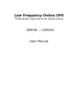
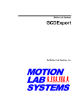
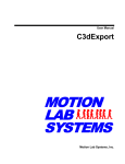
1
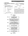
ADT-HCA1003
Simple type Arc Voltage Adjusting
Controller
Operation Instruction
ADTECH (SHENZHEN) TECHNOLOGY CO.LTD
ADT-HCA1003 Arc Voltage THC
I. Product Introduction
1. Product Model
ADT-HCA1003
2. Chinese Name
Simple type arc voltage adjusting controller.
3. Working Application:
It is applicable to automatic control in the height of cutting torch of plasma cutting machine
and is suitable for most of the plasma-types imported or made in China.
4. Working Principle
The theory of the ADT-HCA1003 plasma arc voltage adjusting controller is to utilize the
characteristics of fundamental constant current of plasma power supply and realize the control in
the height of cutting torch through detection of the change in the height of cutting torch during
plasma cutting by detecting the change of plasma arc voltage.
5. Mode of Arc Voltage Detection
Isolated voltage division detection, with the ratio of voltage division of 100:1.
6. Technical Parameter
y
Working voltage: AC220V+5%,50Hz/60Hz;DC24V, over 4A.
y
Lifting motor: 24V DC motor or stepping motor (pulse frequency of 1KHz).
y
y
y
y
y
Output current: 1A
Output power: 20W (DC motor power), the driving power of the stepping motor is
irrelevant to the controller.
Working temperature: adjuster-10∽60℃
Initial localization mode: switch mode initial localization; protective cap contact-type
initial localization.
Operation transmission mode: detection of the enable of arc voltage.
y
Ratio of voltage division:100:1
y
Precision: ±5V
y
External dimensions: L×W×H:195×117×40(mm)
Be sure to read the operation instruction carefully before operation.
1
ADT-HCA1003 Arc Voltage THC
II. Detailed function introduction and method of application
1. Introduction of product shape, composition and characteristics
The product is called as simple type arc voltage adjusting controller and consists mainly of
two parts, including adjusting control box and isolated voltage divider. As shown in the
following figure:
Fig 1 Composition of adjuster
ADT-HCA1003 torch height adjuster has following characteristics:
1.
The torch height adjuster has small size and complete function and is often used in micro
numerical control plasma cutting machine system, and it has such characteristics as easy
operation, simple wiring and stable performance and so on.
2.
It may drive DC motor directly and also drive the stepping motor or servo motor with
positioning control mode.
3. Sample circuit of plasma arc adopts isolated voltage division sampling to realize the
complete isolation of plasma power supply and torch height adjuster.
4. Full automatic control mode, numerical control requires only a starting signal to complete
automatic initial localization and arc starting operation and under any state, the cutting torch
has the function of anti-collision to reach the purpose of protecting the cutting torch.
5. The mode of initial localization may use the protective cap or proximity switch type
positioning and the two modes can be used at the same time.
2. Introduction of Basic Functions and the Working Process of Automatic
2
ADT-HCA1003 Arc Voltage THC
Adjusting of Torch Height Adjuster
The torch height adjuster can realize the control in rising and falling of cutting torch
through control in the operation of DC motor or stepping motor and it has the control interface
with numerical control system to realize automatic control and realize the automatic control in
the height of cutting torch through detecting the actual height of cutting torch by means of
detection of the change in arc voltage.
Completion of
Arc
raised
starting
by
alignment
signal
numerical
With
control to torch height
Auto
adjuster to
alignment
initial
arc
Raise arc voltage
Arc starting signal
enable
to
to plasma
numerical control
and
carryout
No arc voltage after detection
cutting
and
automatic
Waiting for success
adjustment
of arc starting
Figure 2 Schematic diagram of cutting process
The cutting process is shown in figure 2, and when the numerical control system carry out
plasma cutting, the cutting program will set out the arc starting order and after the torch height
adjuster receive the signal it begin to lower the cutting torch, and after the ting nozzle touch the
steel plate to be cut and the positioning signal is sent out, the torch height adjuster will raise the
cutting torch to the arc starting height that has been set up initially, before sending the arc
starting signal to the plasma power supply, and once the arc starting of plasma power supply is
successful, the torch height adjuster will detect the arc voltage and send out the arc voltage
enable signal immediately, and after the numerical control system receive the arc voltage enable
signal, it begins to control the operation of machine tool and open the automatic adjustment
function until completion of the cutting.
3. Function and Wiring Method of Isolated Voltage Divider
The change of plasma arc voltage must be detected when carrying out the control of arc
voltage. The arc voltage of plasma is the voltage between electrode and the ground. Anode of the
3
ADT-HCA1003 Arc Voltage THC
plasma power supply output is connected to the ground and the cathode is connected with the
electrode of the cutting gun; therefore, the voltage on electrode is negative value and the absolute
value of arc voltage when cutting is larger than 100V generally, and because of high voltage, it
must carry out the voltage division to implement control in control circuit.
Isolated voltage divider makes the plasma arc subject non- isolated voltage division and
after processing of isolated circuit, it is connected with the torch height adjuster, so the
disturbance of arc voltage after isolation processing to the torch height adjuster is small. The
Company has provide the user with a voltage divider in the parts with the ADT-HCA1003
machine and the voltage divider may be connected in either non-isolated voltage division or
isolated voltage division, and the wiring methods are shown in Fig.3 below.
AC220V input
-Actual arc voltage input+
100:1 non-isolated voltage
division
output
wiring
position
- Isolated voltage division output+
4
ADT-HCA1003 Arc Voltage THC
Fig 3 Wiring schematic diagram of isolated voltage divider
4. Initial Localization Mode of Torch Height Adjuster
There are two localization modes for the design of the torch height adjuster and the cutting
torch has the function of anti-collision, and under any state if the cutting torch collide with work
piece or material rest, the cutting torch will be raised to reach the purpose of protecting the
cutting torch.
4.1 Localization Detection and Connection Mode of Protective Cap of Cutting Torch
Adoption of the localization requires the metal structure of protective cape and mutual
connection when colliding the steel plate. ADT-HCA1003 has localization circuit that is installed
in the controller directly, and the connection method of the localization interface is shown as
Fig.4 below.
定位导线
Localization lead
SHIELD
喉箍
接工件料架
Hose clamps
Material rest of work piece
定位金属弹片
Localization metal clips
接地
保护帽
Earthing
GND
WORK
Protective cap
割枪
Cutting gun
5
ADT-HCA1003 Arc Voltage THC
Fig 4 Localization wiring of protective cap
Description:
A. SHIELD terminal in localization circuit is connected to the protective cap of cutting
torch.
B. WORK terminal in localization circuit is connected to work piece or material rest.
C. Earthing rod GND must connect to the ground well and the area of cross section shall be
larger than 4mm².
D. When the plasma is these without high frequency arc firing, WORK and GND can be
short-circuited on isolated localization plate. If the plasma is high frequency arc firing,
it is suggested to adopt the a localization mode of proximity switch.
Working process of localization of protective cap: after the torch height adjuster receives
the arc starting signal sent out by numerical control system, the cutting torch will descend
immediately, and when the protective cap touches the steel plate, the torch height adjuster will
accept the signal and control the cutting torch immediately to raise to the localization height that
has been set up, and after completion of the localization, the torch height adjuster will control the
plasma arc starting automatically. The mode may be adopted for the plasma of either touch arc
starting or high frequency arc firing.
4.2 Localization mode of proximity switch
When the localization mode of proximity switch is adopted, the users shall design the
fixture according to the concrete schematic diagram of the cutting torch fixture provided by the
Company. Initial localization of all of the plasma, no matter on water cutting or underwater
cutting, may adopt the kind of localization mode.
The proximity switch shall be under proximity state prior to localization and once it is
detached the cutting torch will be raised immediately.
Working process of adoption of the proximity switch localization: after the torch height
adjuster receives the arc starting signal sent out by the numerical control system, the cutting
torch will descend quickly and when it touches the steel plate the proximity switch will break
away the proximity point, and after the torch height adjuster receives the signal, it will control
the cutting torch to raise to the localization height that has been set up (during the process of the
raising, the proximity switch will reset automatically), after completion of the localization, the
6
ADT-HCA1003 Arc Voltage THC
torch height adjuster will control the plasma arc starting automatically. The mode is applicable to
the initial localization of all the plasma.
The torch height adjuster adopts NPN proximity switch and see the following section for
the wiring method.
5、 Function of Various Interface of Adjustment Box and Wiring Method
As shown in Fig.5, description of various connecting terminals or the torch height adjuster
is as follows:
Protective
localization interface
AC220V
DC
proximity
switch interface
NPN
24V
Numerical
cap
control
DC motor interface
CNC interface
Arc starting and
Arc voltage setting
voltage
given
input
interface
Stepping
motor
driving interface
Regulation resistance for initial localization height setting
Fig. 5 Schematic diagram of interface of torch height adjuster
5.1 Power Supply Interface:
Input power adopts AC 220V and DC 24V power supply and the power of DC power
supply depends on the power of DC power supply, and notice the positive and negative polarities
of DC power supply and do not connect reversed.
5.2 Numerical Control
7
ADT-HCA1003 Arc Voltage THC
Photoelectric isolation mode is adopted for the interface of torch height adjuster and
numerical control and the wiring control method is shown in Fig 6 below
Auto: auto actuation
Ascending: effective actuation
Descending: effective actuation
Localization arc starting: effective actuation
Feedback output: switch signal
Common terminal of control
Fig 6. Schematic diagram of CNC interface
Definition and description of various signals
A. Auto/manual signal (AUTO): automatic input low level; manual high level
B. Ascending(UP):effective low level;
C. Descending (DOWN):effective e low level;
D. Arc starting signal(ARCON)with initial localization: effective e low level, during
operation carry out initial localization at first and the arc starting is implemented
automatically after localization.
E. Arc starting or perforation completion signal(ARCTRANS1 and ARCTRANS2):output
signal of switching value
F. Control common terminal(COM):: control common terminal of signal
5.3 Specified Arc Voltage Setting
The torch height adjuster adopts a adjustable multi-turn potentiometer as the specified arc
voltage input and the specified voltage is about 90V when rotating the potentiometer
counterclockwise to the minimum value, and the specified arc voltage will be increased
when rotating the potentiometer counterclockwise, with increase of 10V for each full round
and the range of specified arc voltage of 90~~200V.
The arc voltage when cutting shall be set up according to the parameter table of the plasma
equipment provide and on the basis of the thickness of the materials to be cut and the cutting
speed. The specified voltage decides the height during cutting and if the specified arc voltage
increase the cutting height will increase, and under the auto state during cutting, the cutting
8
ADT-HCA1003 Arc Voltage THC
height may be adjusted through adjusting the specified arc voltage.
5.4 Height Setting Potentiometer of Initial Localization(Set
IHS):
Setting the height of the initial localization of cutting torch during arc starting, namely after
sending out the arc starting signal, the cutting torch will descend until detecting the localization
signal (such as the protective cap contacts the work piece during localization) and then ascend.
The height, when rotating the potentiometer clockwise, will decrease and will increase when
rotating the potentiometer counter-clockwise, and the latter is controlled through the mode of
time delay.
Arc starting of different plasma power supply requires different height and the users shall
adjust it according to the actual conditions.
5.5 Protective Cap Localization Interface:
See description in section 2 for the detailed wiring method of protective cap.
5.6 Proximity Switch Localization Interface:
NPN proximity switch is adopted, with COM terminal as the negative terminal and VCC
terminal as the positive terminal, and SINGLE(signal)is connected with the signal input
terminal of proximity switch. Please implement short-circuit connection if the proximity switch
is not used for localization.
5.7 DC Motor Interface:
When the DC motor is connected, the DC motor under 20W may be driven directly.
5.8 Arc Starting and Arc Voltage Input Interface:
ARC+ and ARC- are arc voltage input interface and is connected with the plasma arc
voltage signal output by isolated voltage division of voltage divider and ARC+ is connected to
the positive terminal of arc voltage and ARC- is connected to negative terminal of arc voltage;
and the arc starting signal is a group of switch output of relay and is closed during arc starting.
5.9 Stepping Motor Driving Output Interface:
As shown in Fig 7 below
9
ADT-HCA1003 Arc Voltage THC
Stepping driver
Two
wiring
methods:
determined
according to the wiring methods of
stepping motor drivers.
Stepping driver
Fig 7 Stepping motor driving interface
When using the stepping motor, DIR is the direction signal and PULSE stands for drive
pulse signal and the concrete wiring method is subject to the stepping motor driver. Output pulse
frequency during operation is 1 KHz and if the users want to alter the frequency please contact
the manufacture in advance.
Note: the product is of the simple type, so limit interface of lifting motor is not provided
and if the users want it please think over it.
III. Suggestions
1. When the protective cap is used for localization, we suggest that the users shall install the
anti-collision fixture at the same time and connect the localization mode of protective cap, so
that during the actual usage, if the protective cap fails to contact the cutting plate well, the
proximity switch localization is effective at the same time, so it is propitious to protecting the
cutting torch. In case of installation at the same time by two localization modes, the
anti-collision functions of two localization shall be effective.
2. Shielded cable shall be adopted for connection from isolated voltage division plate to torch
height adjuster and shall be separated from the cable for arc starting.
Special suggestion:
10