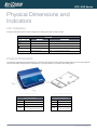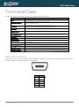
1
Intelligent M2M Serial Modem NTC-4000 SERIES USER GUIDE NTC-4000 Series Wireless M2M Copyright Copyright©2011 NetComm Limited. All rights reserved. The information contained herein is proprietary to NetComm Limited. No part of this document may be translated, transcribed, reproduced, in any form, or by any means without prior written consent of NetComm Limited. Please note: This document is subject to change without notice. Save Our Environment When this equipment has reached the end of its useful life, it must be taken to a recycling centre and processed separately from domestic waste. The cardboard box, the plastic contained in the packaging, and the parts that make up this device can be recycled in accordance with regionally established regulations. Never dispose of this electronic equipment along with your household waste. You may be subject to penalties or sanctions under the law. Instead, ask for disposal instructions from your municipal government. Please be responsible and protect our environment. This manual covers the following products: NetComm NTC-4908 NetComm NTC-4520 DOCUMENT VERSION DATE 1.0 - Initial document release 01/06/2011 2.0 - New layout implementation 22/08/2011 3.0 – Updated to include NTC-4520 28/12/2011 4.0 – Corrected Modem Initialisation and SerialNET instruction set 09/10/2012 5.0 – RJ-45 to DB-9 pin out diagram updated 16/01/2013 Table 1 - Document Revision History NTC 4000 Series – Intelligent M2M Serial Modem 2 YML-OUM-N4K www.netcommwireless.com Wireless M2M NTC-4000 Series Table of Contents Overview ........................................................................................................................................................................................ 4 Introduction ................................................................................................................................................................................................... 4 Target Users.................................................................................................................................................................................................. 4 Prerequisites.................................................................................................................................................................................................. 4 Notation ........................................................................................................................................................................................................ 4 Product Introduction ..................................................................................................................................................................... 5 Product Overview .......................................................................................................................................................................................... 5 Physical Dimensions and Indicators ............................................................................................................................................ 6 LED Indicators ............................................................................................................................................................................................... 6 Physical Dimensions ...................................................................................................................................................................................... 6 Integrated Interfaces ..................................................................................................................................................................... 7 Safety and Product Care ............................................................................................................................................................... 8 Transport and Handling ................................................................................................................................................................................. 8 Hardware Installation..................................................................................................................................................................... 9 Inserting the SIM card .................................................................................................................................................................................... 9 Mounting Options ........................................................................................................................................................................................ 10 Connecting the Data/Power cable ................................................................................................................................................................ 12 Connecting via mini USB.............................................................................................................................................................................. 12 Communicating with a NTC-4000 Series Modem ..................................................................................................................... 16 Dumb Terminal ............................................................................................................................................................................................ 16 Enhanced AT Commands ............................................................................................................................................................................ 17 Modem Initialisation Steps ........................................................................................................................................................................... 18 SerialNET .................................................................................................................................................................................................... 21 Dial-up Networking ...................................................................................................................................................................................... 24 Implementation and Deployment Scenarios .............................................................................................................................. 31 Electricity Metering / SCADA Device ............................................................................................................................................................. 31 Remote Security System .............................................................................................................................................................................. 33 Remote Parking Meter ................................................................................................................................................................................. 35 Remote Weather Monitoring ........................................................................................................................................................................ 36 Back-end Server Deployment: ..................................................................................................................................................................... 36 Dialling into a Back-end Server Hosted Modem ............................................................................................................................................ 36 Utilised AT Command Reference ................................................................................................................................................ 37 AT+i Result Code Summary ......................................................................................................................................................................... 76 Technical Data ............................................................................................................................................................................. 79 Mini USB Connector .................................................................................................................................................................................... 79 RJ-45 Connector ......................................................................................................................................................................................... 80 RJ-45 to DB-9 Serial/Power Adapter Cable .................................................................................................................................................. 80 Electrical Specifications................................................................................................................................................................................ 81 Environmental Specifications / Tolerances .................................................................................................................................................... 81 Product Service and Support ...................................................................................................................................................... 82 Troubleshooting........................................................................................................................................................................................... 82 Web Based Product References .................................................................................................................................................................. 84 FAQs........................................................................................................................................................................................................... 85 Abbreviations and Terminology .................................................................................................................................................. 86 Appendix A: Tables...................................................................................................................................................................... 87 Legal and Regulatory .................................................................................................................................................................. 89 Intellectual Property Rights ........................................................................................................................................................................... 89 Customer Information .................................................................................................................................................................................. 89 Consumer Protection Laws .......................................................................................................................................................................... 89 Product Warranty ........................................................................................................................................................................................ 90 Limitation of Liability ..................................................................................................................................................................................... 90 Contact......................................................................................................................................................................................... 91 YML-OUM-N4K www.netcommwireless.com NTC 4000 Series – Intelligent M2M Serial Modem 3 Wireless M2M NTC-4000 Series Overview Introduction This document details the process of configuring the NTC-4000 Series device via a terminal emulation programme (such as HyperTerminal) as well as mounting and deployment advice. This advice will include a few demonstration deployments and an explanation of related technologies that this M2M device is suitable for. Target Users This document is expected to be utilised by system integrators or experienced hardware installers who are comfortable with all aspects of IP based networking and an understanding of serial based technologies such as dialup modems, AT commands and legacy data collection devices. Prerequisites A computer with a terminal emulation programme (such as HyperTerminal), a serial port, appropriate power supply and a device to connect to the NTC-4000 Series modem after configuration has been completed. Notation The following symbols are utilised in this user manual: The following note requires attention The following note provides a warning The following note provides relevant information. NTC 4000 Series – Intelligent M2M Serial Modem 4 YML-OUM-N4K www.netcommwireless.com NTC-4000 Series Wireless M2M Product Introduction Product Overview Industrial grade RS-232 modem for wireless data communication supporting networks and various service types: UMTS/HSDPA/HSUPA and GSM/GPRS/EDGE Embedded 3G/2G multi-mode modem module ConnectOne iChip ARM7-based microcontroller Embedded Internet and security protocol stacks Supports standard and extended AT command set RS232 data connection and DC power input via RJ-45 port Extended operating temperature range -20 to 55°C Wide input voltage range 8-56V DC suitable for diverse environments and applications Lockable SIM card tray Small rugged form factor with two LED indicators DIN rail and wall mount option with removable mounting bracket Package Contents The NTC-4000 series package consists of: NTC-4000 Series Modem RS-232 Data/Power Cable 1m 3G Antenna with SMA connector Mounting bracket Quick Start Guide If any of these items are missing or damaged, please contact NetComm Support immediately by visiting the NetComm Support website at: http://support.netcommwireless.com/ . Product Features The NTC-4000 Series enables serial based legacy devices to take part in a modern IP networking environment. Traditionally, this equipment relied on PSTN infrastructure and utilised the Hayes AT Command Set to configure an attached modem which could then dial out to a modem attached to a backend server. Once the two modems are connected, data can be exchanged. The NTC-4000 series offers additional IP connectivity by utilising an enhanced AT command set which enables non-network aware (dumb) devices to communicate through the NTC-4000 and out to the Internet or circuit switched based services. The NTC-4000 Series also features a built-in WWW and Telnet server enabling 2 way communications with attached devices. (if supported by the device) YML-OUM-N4K www.netcommwireless.com NTC 4000 Series – Intelligent M2M Serial Modem 5 NTC-4000 Series Wireless M2M Physical Dimensions and Indicators LED Indicators The NTC-4000 Series uses two LEDs to display the current system and connection status. NTC-4000 LED INDICATOR Power 3G COLOUR DEFINITION Off The Power is Off Red The Power is on and the NTC-4000 is operating normally Off The NTC-4000 is not connected to a 3G network. Slow flashing green The NTC-4000 is attempting to connect to a 3G network. Quick flashing green Data is moving across the 3G connection. Table 2 - LED Indicators Physical Dimensions The following page lists the physical dimensions of the NTC-4000 Series as well as the physical dimensions of the mounting bracket which can be used to attach the NTC-4000 Series to a Type-O DIN Rail or to provide a wall / ceiling mount. Figure 1 - NTC-4000 Series Dimensions NTC-4000 SERIES MOUNTING BRACKET Length 74 mm Length 80 mm Width 57 mm Width 45 mm Height 24 mm Height 5 mm Weight 85g (w/o mounting bracket and antenna) Table 3 - Device Dimensions NTC 4000 Series – Intelligent M2M Serial Modem 6 Figure 2 - NTC-4000 Series Mounting Bracket Weight 10g (w/o NTC-4000 attached) Table 4 - Mounting Bracket Dimensions YML-OUM-N4K www.netcommwireless.com NTC-4000 Series Wireless M2M Integrated Interfaces The following integrated interfaces are available on the NTC-4000 Series: INTERFACE RJ-45 (RS-232 DB-9 adapter / Power) Mini USB FUNCTION Connectivity to attached device and power Connectivity via a virtual COM port (after driver installation) Table 5 - Integrated Devices Please note: The driver required for the mini USB virtual COM port is available from the NTC-4000 Series Product Support page at: http://support.netcommwireless.com/product/m2m/ntc-4000 YML-OUM-N4K www.netcommwireless.com NTC 4000 Series – Intelligent M2M Serial Modem 7 NTC-4000 Series Wireless M2M Safety and Product Care The NTC-4000 series offers a hardened industrial enclosure making it suitable for a variety of remote deployment locations. With reference to unpacking, installation, use and maintenance of your electronic device, the following basic guidelines are recommended: Do not use or install this product near water to avoid fire or shock hazard. For example, near a bathtub, kitchen sink, laundry tub, or near a swimming pool. Also, do not expose the equipment to rain or damp areas (e.g. a wet basement). Do not connect the power supply cord on elevated surfaces. Allow it to lie freely. There should be no obstructions in its path and no heavy items should be placed on the cord. In addition, do not walk on, step on or mistreat the cord. To safeguard the equipment against overheating, make sure that all openings in the unit that offer exposure to air are unobstructed. Transport and Handling When transporting the NTC-4000 Series, it is recommended to return the product to the original packaging. This ensures the product will not be damaged. In the event the product needs to be returned, ensure it is securely packaged with appropriate padding to prevent damage during courier transport. NTC 4000 Series – Intelligent M2M Serial Modem 8 YML-OUM-N4K www.netcommwireless.com NTC-4000 Series Wireless M2M Hardware Installation Inserting the SIM card Please ensure that the NTC-4000 is not connected to the power cable before proceeding. 1. Push the small yellow button besides the SIM card holder. Figure 3 – Accessing the NTC-4908 SIM Card Slot 2. Insert the SIM card into the holder with the golden pins facing up. Figure 4 - Inserting a SIM Card into the NTC-4908 SIM Card Holder YML-OUM-N4K www.netcommwireless.com NTC 4000 Series – Intelligent M2M Serial Modem 9 NTC-4000 Series Wireless M2M 3. Insert the SIM card holder with the SIM conductor pins facing down into the NTC-4000. Figure 5 –Face Down Insertion of the SIM Card and SIM Card Holder Mounting Options The NTC-4000 series modem can be mounted on the wall or a DIN rail by using the mounting bracket. The mounting bracket is made from polyamide, which is a flexible material. Mounting the NTC-4000 series modem is as simple as bending the mounting bracket to snap into place on the Type-O (Top Hat) DIN rail. This holds the NTC-4000 series modem in place securely. Alternatively, the mounting bracket can be screwed onto a wall to provide a permanent fixture. DIN rail mounting The NTC-4000 Series mounting bracket has been designed to fit a TS 35 Type-O DIN rail with a 25mm core. 1. Bend / Flex the mounting bracket at the bend line so that the ridges are able to ‘hold’ onto the DIN rail edges as per the diagram above. You also have the option of securing the mounting bracket further by screwing it into place on the rail. Figure 6 - NTC-4908 - Mounting Bracket - DIN Rail NTC 4000 Series – Intelligent M2M Serial Modem 10 YML-OUM-N4K www.netcommwireless.com NTC-4000 Series Wireless M2M 2. Once the bracket is attached to the DIN rail, slide the NTC-4000 Series modem into the mounting bracket to securely fix it in place. Figure 7 - Securing the NTC-4908 Mounting Bracket to the DIN Rail Wall Mounting 1. Select the location you would like to attach the NTC-4000 Series modem to. Attach the mounting bracket to the chosen wall or ceiling by using the 4 screw holes (screws not included). 2. Once the bracket is attached to the DIN rail, slide the NTC-4000 Series modem into the mounting bracket to securely fix it in place. YML-OUM-N4K www.netcommwireless.com NTC 4000 Series – Intelligent M2M Serial Modem 11 NTC-4000 Series Wireless M2M Connecting the Data/Power cable Figure 8 - Connecting the RJ-45 Ethernet / Power Cable to the NTc-4908 1. Connect the included antenna to the SMA connector of the NTC-4000. 2. Plug the included RS-232 data/power cable into the RJ-45 socket of the NTC-4000 and then plug the serial port (DB9) end of the same cable into the COM port of the device you would like to connect to. 3. Connect a compatible power adapter to the DC power jack (2.1mm barrel) of the RS-232 data/power cable and then plug the power adapter into a power outlet. Please note: It is not possible to utilise the mini-USB and Serial connection concurrently. Make sure any open connection on the Serial port is disabled before connecting via the mini-USB cable. Connecting via mini USB The mini USB connection enables communication from a Windows computer via a virtual COM port. The NTC-4000 Series can then be configured via a terminal emulator (such as HyperTerminal). The steps below are for installing the driver under Windows XP: 1. NTC-4000 Series Drivers are available from the NetComm Support website at http://support.netcommwireless.com/product/m2m/ntc-4000 . Download and extract them to a folder on the computer that will be attached to the NTC-4000 Series router. 4. Connect the mini USB cable to the USB port on the back of the NTC-4000 Series. 5. Connect the other end of the mini USB cable to a spare USB port on the computer. 6. When prompted, install the mini USB driver using the following steps: a) Select “No, not at this time” and then click “Next”. . Figure 9 - NTC-4908 USB Driver Installation – Windows Found New Hardware Wizard NTC 4000 Series – Intelligent M2M Serial Modem 12 YML-OUM-N4K www.netcommwireless.com NTC-4000 Series Wireless M2M b) Select “Install from a list or specific location (Advanced)” and click “Next”. Figure 10 - NTC-4908 USB Driver Installation – Select Driver Location c) Select “Don’t search, I will choose the driver to install” and click “Next”. Figure 11 - NTC-4908 USB Driver Installation – Select Driver to Install d) Select “Ports (COM & LPT)” and click “Next”. Figure 12 - NTC-4908 USB Driver Installation – Select COM Ports Hardware Type e) Select “Have Disk” and then click “Browse” and navigate to the location the drivers were extracted to. Figure 13 - NTC-4908 USB Driver Installation – Select Extracted Driver Fil YML-OUM-N4K www.netcommwireless.com NTC 4000 Series – Intelligent M2M Serial Modem 13 NTC-4000 Series Wireless M2M f) Select the “iChip.inf” file and click “Open”. Figure 14 - NTC-4908 USB Driver Installation – Select the 'iChip.inf' Driver File g) Select the “Connect-One iChip Sabalo” and click “Next”. Figure 15 - NTC-4908 USB Driver Installation – Connect-One-iChip-Sabalo Option h) When prompted, click the “Continue Anyway” button to continue the NTC-4000 Series driver installation. Figure 16 - NTC-4908 USB Driver Installation – Driver Compatibility Warning 7. Once the installation has finished you should see the following: Figure 17 - NTC-4908 USB Driver Installation – Final Driver Installation Step NTC 4000 Series – Intelligent M2M Serial Modem 14 YML-OUM-N4K www.netcommwireless.com NTC-4000 Series Wireless M2M To verify the driver was successfully installed check in the Device Manager for an extra COM port. To check the Device Manager, perform the following steps: 1. Click on the Start button and navigate to the “Control Panel” option. 8. Double click on the “System” Control Panel item. 9. Click on the “Hardware” tab and then click the “Device Manager” button. 10. In the device list, the following should be shown: Figure 18 - NTC-4908 USB Driver Installation - Device Manager Details If the Connect-One iChip Sabalo is not listed, please reboot your computer and attempt the driver installation again. If this still fails, please contact NetComm Wireless Technical Support at: http://support.netcommwireless.com/ YML-OUM-N4K www.netcommwireless.com NTC 4000 Series – Intelligent M2M Serial Modem 15 NTC-4000 Series Wireless M2M Communicating with a NTC4000 Series Modem Dumb Terminal Either via the device’s serial port, or via the USB port once the virtual COM port driver has been installed, any terminal emulator can be utilised to facilitate communication to the NTC-4000 Series. In the example below, HyperTerminal from Windows XP is shown. 11. Click on the Start button and then navigate to the “Accessories” item and then “Communications”. 12. Click on the “HyperTerminal” item. 13. Enter a name for the connection profile (for example: NTC-4000) and click “OK”. 14. On the “Connect to” window, select the virtual COM port (which was created by installing the NTC-4000 driver) in the “Connect using” dropdown menu. Figure 19 - NTC-4908 Operation Settings - Select COM Port 15. On the COM port settings window that appears, select “115200” in the “Bits per second” dropdown menu. Figure 20 - NTC-4908 Operation Settings - Baud Rate Selection The terminal window should then display indicating a connection is open to the NTC-4000 Series. This can be tested by entering the command “at+i” and receiving the response “I/OK” as shown below: NTC 4000 Series – Intelligent M2M Serial Modem 16 YML-OUM-N4K www.netcommwireless.com Wireless M2M NTC-4000 Series Using the hyper-terminal and the enhanced AT command set the NTC-4000 Series router can be configured to perform customised operations. Please refer to the AT Command Set guide for more information on the functions available. If you are unable to type “at+i” (without quotations), check that you have selected the correct COM port to attempt to connect on. Alternatively, try to open a connection utilising a physical COM port with the DB-9 cable attached. Enhanced AT Commands The NTC-4000 is capable of far more than a standard serial modem. The NTC-4000 series offers additional IP connectivity by utilising an enhanced AT command set which enables non-network aware (dumb) devices to communicate through the NTC-4000 and out to the Internet or circuit switched based services. These enhanced AT Commands can be used to instruct the ConnectOne iChip built into the NTC-4000 to connect to the internet, and perform a variety of IP based functions. Basic AT Commands and raw data are transparently transferred to the underlying modem, whilst enhanced AT+I commands are parsed and acted upon by the NTC-4000’s embedded iChip, providing a wide variety of additional functionality. For a full list of the enhanced AT Commands supported, please refer to the AT Command Set guide available from the NetComm website at: http://www.netcommwireless.com/product/m2m/ntc-4000 YML-OUM-N4K www.netcommwireless.com NTC 4000 Series – Intelligent M2M Serial Modem 17 NTC-4000 Series Wireless M2M Modem Initialisation Steps Enter the following commands in sequence to prepare the NTC-4000 Series to connect to the internet. Each time the NTC-4000 Series device is reset to default settings, the following commands will need to be entered in order to initialise the device. After device initialisation, these commands are persistent, unless the device is once again, reset to default settings. 1. Enter the following commands to reset the unit to defaults, and instruct the iChip as to the correct communications interfaces, and modem settings. at+ifd at+ihif=2 at+ibdrf=9 at+imif=5 at+iCPF? If value returned is 1, enter: at+iCPF =0 2. For the NTC-4908, the modem type should also be set as follows: at+imtyp=2 3. For the NTC-4520, the modem type should also be set as follows: at+imtyp=14 4. For the NTC-4520 model only, the chipset function should be set to 1 for full functionality using the “at+cfun=1” command. The default chipset function setting is 4 which sets the NTC-4520 into flight mode, disabling the mobile broadband signal. at+cfun=1 This means that each time the NTC-4520 is powered on the chipset function is set to 4(flight mode) disabling the mobile broadband signal. To ensure the NTC-4520 has full functionality every time it is powered up and initiates an internet connection, make sure to add the command at+cfun=1 command to the modem initialisation string (at+iMIS). This is suitable when the NTC-4520 initiates a dial-up internet session, such as when SerialNet or a triggered at+itup command Is used. An example is shown below: at+iMIS="AT+CGDCONT=1,\"IP\",\"< ENTER YOUR 3G PROIVDER APN >\";at+cfun=1" (where < ENTER YOUR 3G PROIVDER APN> should be the APN suitable for your mobile broadband connection.) 5. Power cycle the NTC-4000 Series device and allow 30 seconds for the modem to enumerate on the USB port, The NTC-4000 Series device is now ready to be used, either via a dial up internet session, or via the embedded IP stack. Warning: Do not reset the NTC-4000 to factory defaults (at+ifd) without running these initialisation commands PRIOR to power cycling the device. Otherwise the NTC-4000 may incorrectly assign the serial host interface to the embedded cellular modem instead of the serial port. The automatic host detection searches for ‘a’ characters in order to operate. Therefore, if this occurs, the NTC-4000 can be recovered by repeatedly sending ‘a’ key via a dumb terminal immediately after power up. Once access to the NTC-4000 has been restored, please follow the remaining initialisation steps listed above. The definitions of the commands used in the above examples are listed in the table below: AT COMMAND at+ifd at+ihif=2 DEFINITION Restore all parameters to Factory Defaults Specify the host interface for communication (0 = Automatic host interface detection) at+ibdrf=9 Define a fixed baud rate on host communication (9 = Set baud rate to 115200) at+imif=5 Set the modem interface (5 = USB Host) NTC 4000 Series – Intelligent M2M Serial Modem 18 YML-OUM-N4K www.netcommwireless.com NTC-4000 Series Wireless M2M at+imtyp=14 at+imtyp=2 at+iCPF=0 at+cfun=1 at+iMIS Set the type of modem connected to the iChip appropriate for the NTC-4520 Set the type of modem connected to the iChip appropriate for the NTC-4908 Set the active communications platform to modem. Set the iChip function to full functionality appropriate for the NTC-4520. (The default cfun setting for the NTC-4520 is 4 which sets the modem function to flight mode.) Set the modem initialization string including PDP type (packet data protocol) and APN Table 6 - NTC-4908 Initialisation Step Details YML-OUM-N4K www.netcommwireless.com NTC 4000 Series – Intelligent M2M Serial Modem 19 NTC-4000 Series Wireless M2M Example enhanced AT Commands The enhanced AT Commands necessary to establish an internet connection vary depending on the exact usage scenario of the device. It is advised that a user becomes familiar with all commands supported by the device, as a proper understanding of the commands and their function will be required in order to use this product. Below is a set of example commands to connect to the internet using an NTC-4000 Series product. This is intended to be an example only, and users should refer to the full list of commands as alternate commands may be required depending on the application and environment. First ensure that the device has been initialised following the instructions in the section above. Next, to configure the embedded IP Stack to connect to the internet, run the following commands: at+iMIS="AT+CGDCONT=1,\"IP\",\"<ENTER YOUR 3G PROIVDER APN>\" at+iisp1=*99# ate1 at+cfun=1 The NTC-4000 Series device is now ready to connect to the APN specified in the at+iMIS command. The definitions of the commands used in the above examples are listed in the table below: AT COMMAND DEFINITION at+iMIS=”AT+CGDCONT=1,\”IP\”,\”<3G Provider APN>\” at+iisp1=*99# ate1 at+cfun=1 Set the APN to use when connecting to the 3G service Set the ‘Dial Number’ for a 3G data connection Set local echo mode on the NTC-4520 (F5521GW module) Set phone functionality for the 3G module to full. Please note that the embedded cellular module on the NTC-4520 model has the default value of AT+CFUN=4 (This is flight mode). For full functionality, set AT+CFUN=1. Table 7 - NTC-4908 Example AT Command Set – 3G Service Setup The following commands are examples which can be used to connect and test connectivity to the selected 3G service: Please Note: If the SIM Security is enabled, enter the PIN code using the command: at+cpin=xxxx (where xxxx is the PIN code). To check whether SIM Security is enabled: use the command: at+cpin? AT COMMAND DEFINITION at+irp2 This command verifies whether NTC-4000 Series device is in command mode. The NTC-4000 Series should return the following output in the terminal, indicating it is ready to connect to the Internet: Command Mode at+iup This command tells the NTC-4000 Series device to connect to the 3G service specified by the at+iMIS command. The NTC-4000 Series should return the following output in the terminal indicating it has successfully connected to the Internet: I/OK I/ONLINE at+iipa? This command tells the NTC-4000 Series device to display the IP address obtained from the specified 3G service. The NTC-4000 series should return: <The current IP address> I/OK at+iping=<IP address to ping> at+irlnk=http://www.go ogle.com/ at+itup:2 This command tells the NTC-4000 Series device to attempt to ping the specified IP address. The NTC-4000 Series should return the ping time in milliseconds that a ping test took to transmit to and from a the specified IP address: I/(0259) This command tells the NTC-4000 Series device to retrieve the URL specified in the at+irlnk command. The NTC-4000 Series should return: I/OK I/222 <HTML><HEAD><meta http-equiv="content-type" content="text/html;charset=utf-8"> <TITLE>302 Moved</TITLE></HEAD><BODY> <H1>302 Moved</H1> The document has moved <A HREF="http://www.google.com.au/">here</A>. </BODY></HTML> I/DONE This indicates the URL was successfully retrieved. This command tells the NTC-4000 Series device to automatically reconnect to the internet. This is useful to reconnect automatically after a power loss. Table 8 - NTC-4908 Example AT Command Set - AT Command Functions and Expected Output NTC 4000 Series – Intelligent M2M Serial Modem 20 YML-OUM-N4K www.netcommwireless.com NTC-4000 Series Wireless M2M SerialNET SerialNET mode allows the conversion of serial data to TCP/IP without changes being made to the host device application. It provides an asynchronous serial link over TCP or UDP across a socket or internet connection so that devices that normally connect over a serial line can interface with an IP network. Devices that communicate with a terminal over a serial link fall into three main categories: output only (e.g. Printers), input only (e.g. Controllers) and interactive (bi-directional communication). Interactive devices can be clients or servers. Generally clients initiate communications by sending service demands to a server while servers respond to client demands. SerialNET mode responds differently to client or server devices. When a local client initiates communication SerialNET mode must establish a network connection to a remote server before data can be transmitted between the two systems. When a remote client needs to invoke a device it first needs to contact the NTC-4908 so that SerialNET can be invoked to provide the communication flow to the local server device. SerialNET mode will route full-duplex data between a network terminal and either a client or server device. Example SerialNET mode setup Table 9 - NTC-4908SerialNET Telnet Example Network Topology SerialNet can be set up in a number of different modes. For a full explanation, please see the AT command manual found on the NetComm website at http://www.netcomm.com.au/products The instructions below are an example only. Depending on the requirements of an application, different SerialNET modes might be more applicable. The following commands give an example SerialNET mode setup so that communications from a remote client can be made across the internet using Telnet. All serialNET mode options must be pre-configured as once SerialNET mode is invoked no more AT commands can be configured. The example below provides instructions to configure SerialNET as a listening server, open to incoming TCP connections. In order for a remote host to ascertain the WWAN IP address that the SerialNet server is dynamically assigned from the network, this example includes the configuration of IP Registration via Email. IP Registration is used so that a remote client can automatically learn the WWAN IP address a SerialNET server is configured with via an email automatically sent when SerialNet mode is started. In the example instructions below the remote client device having been sent the WWAN IP address that the NTC-4000 has been assigned can then connect to the NTC-4000 via telnet. YML-OUM-N4K www.netcommwireless.com NTC 4000 Series – Intelligent M2M Serial Modem 21 NTC-4000 Series Wireless M2M SerialNET and Telnet Example Instruction Set 1. Plug a cable from your computer to your NTC-4000 and using the terminal settings, modem initialisation steps and example enhanced AT Commands as a reference ensure your NTC-4000 is connected via mobile broadband and is online. 2. Make sure your NTC-4000 is configured using a suitable SIM card and APN that provides a public IP address. 3. Get details of an email SMTP server, which allows the sending of emails (SMTP server, authentication username/password). 4. Test your SMTP server account details to make sure they work first (i.e. in outlook). 5. Open a serial connection from your NTC-4000 to your computer. 6. Initialise the NTC-4000 to bring it online using the steps previously set out from page 16-19. 7. Enter the following additional AT commands to configure the Email Registration and SerialNET settings. AT COMMAND DEFINITION IP Registration - Email Settings [email protected] Enter the email address to send the email to for general emails. AT+iRRMA= [email protected] Enter the email address to send email to for IP registration. [email protected] Enter the email address you are sending from. AT+iSMTP=anotherisp.com.au Enter outgoing server address to be used to send the email. AT+iSMA=1 Enter whether authentication is required. 0 = no, 1 = yes. AT+iSMU=John.Doe Enter the SMTP username. AT+iSMP=John.Doe.Password Enter the SMTP password. SerialNET Settings AT+iLRPT=23 Enter the listening port for SerialNET, e.g 23 for Telnet. AT+iSNSI=”9,8,N,1,0” Set this to match your serial device. E.G “9,8,N,1,0” 9 for 115200 baud rate, 8 bits start, 1 bit stop, no parity, no flow control at+imcbf=1 Set the memory buffers used by SerialNET to send out data as soon as it is received. AT+iSNMD=2 Invoke SerialNET mode. Table 10 - SerialNET Configuration - Email Registration and SerialNET Initialisation 8. On invoking SerialNET mode an email should be sent to the email address you specified with the format of http://<IP ADDRESS> : <port> 9. On the remote client open a command prompt and type “telnet <IP ADDRESS>.Enter some text and check that is received by the serial terminal connected to the NTC-4000. Check that what is typed in the serial interface is transferred to the telnet interface similar to the example in the table below. Serial Interface Telnet Interface Table 11- SerialNET with Telnet Example - Successful Serial to Telnet (IP Networking) Output 10. To exit out of SerialNET mode enter 3 or more + signs e.g. “+++” and press enter in the Serial interface. You should then be given a message stating I/OK. Alternatively to end the SerialNET mode session the local device can send a disconnection string as specified in the “AT+iDSTR” command. See the AT commands later in the manual. NTC 4000 Series – Intelligent M2M Serial Modem 22 YML-OUM-N4K www.netcommwireless.com NTC-4000 Series Wireless M2M Other Useful SerialNET Commands Transmitting Packets Data originating in the local device is buffered, packetized and transmitted to the remote system over the network. Packets are formed as a result of meeting at least one of the following criteria: 1. A predetermined amount of bytes have been received from the local link. AT+iMCBF=x where x can be 0-1460. The default automatic value is 0. 2. The TCP/IP connection MTU was met. 3. A predetermined hexadecimal flush character has been received (AT+iFCHR=x). 4. A predetermined inactivity timeout event was triggered (MTTF - 0 - 65535). The default 0 value disables this value. Until one of these events occurs, data is buffered in iChip. When an event occurs, a packet is transmitted. Setting AT+i parameters prior to initiating SerialNET mode configures the event parameters. When a UDP connection is used, data packets are atomic, maintaining their original size. When a TCP connection is used packets may be combined before being actually transmitted. This follows from the stream nature of the TCP protocol. Buffering Data MBTB – Maximum Bytes to Buffer. Permanently sets max bytes to buffer while the iChip is establishing an Internet connection. SerialNET Failed Connection If iChip fails to establish a SerialNET connection, SerialNET mode will be deactivated for a delay period defined in the SNRD (SerialNET Device Re-Initialization Delay) parameter. Thiis field is measured in seconds from 0 – 3600. There are many more configurations and AT Commands that can be used with SerialNET. The full AT command manual is available from the NetComm website at http://www.netcommwireless.com/product/m2m/ntc-4000 YML-OUM-N4K www.netcommwireless.com NTC 4000 Series – Intelligent M2M Serial Modem 23 NTC-4000 Series Wireless M2M Dial-up Networking The NTC-4000 can be used to dial up to the internet and provide networking using a standard serial modem driver. Example screenshots are shown below to demonstrate this process using Windows 7, however similar steps can be utilised in other operating systems. 1. Open the Control Panel window using the Start Menu. Figure 21 – Dial-Up Networking - Open Control Panel 2. Type modem into the search field, and then select Phone and Modem. Figure 22 - – Dial-Up Networking - Phone and Modem Options NTC 4000 Series – Intelligent M2M Serial Modem 24 YML-OUM-N4K www.netcommwireless.com NTC-4000 Series Wireless M2M 3. Select the Modems tab, and then click Add. Figure 23 – Dial-Up Networking - Add Modem 4. Select Don’t detect my modem; I will select from a list and then click Next Figure 24 - – Dial-Up Networking - Select Modem YML-OUM-N4K www.netcommwireless.com NTC 4000 Series – Intelligent M2M Serial Modem 25 NTC-4000 Series Wireless M2M 5. Wait a few moments until the list is loaded, then select Standard 33600 bps modem from the list, and click Next. Figure 25 – Dial-Up Networking - Select standard 33600 bps Modem 6. Select the port that the NTC-4000 is connected to and select Next. In the example screenshot below, the NTC-4000 is connected via the serial cable to port COM1. Figure 26 – Dial-Up Networking - Select Port NTC 4000 Series – Intelligent M2M Serial Modem 26 YML-OUM-N4K www.netcommwireless.com NTC-4000 Series Wireless M2M 7. Wait a few moments whilst Windows installs the driver and click Finish on the final screen of the wizard. Figure 27 – Dial-Up Networking - Add Dial-Up Modem Completion 8. The modem must now be modified to add a special initialisation string to pass the APN information required by your service to connect to the cellular network. To do this, ensure that the new modem is selected on the Phone and Modem menu, and click properties. Figure 28 – Dial-Up Networking - Select Modem Properties YML-OUM-N4K www.netcommwireless.com NTC 4000 Series – Intelligent M2M Serial Modem 27 NTC-4000 Series Wireless M2M 9. Click Change settings and wait a moment for the window to reload. Figure 29 - – Dial-Up Networking - Change Modem Settings 10. Click on the Advanced tab, and type the following initialization commands in the Extra initialization commands field: at+cgdcont=1,"IP","apn" The ‘apn’ is your Access Point Name (e.g. for Telstra you would type in at+cgdcont=1,"IP","telstra.internet" ) Figure 30 - – Dial-Up Networking - Add Initialisation String NTC 4000 Series – Intelligent M2M Serial Modem 28 YML-OUM-N4K www.netcommwireless.com NTC-4000 Series Wireless M2M 11. After entering the Extra initialisation command, click OK, exit from the Phone and Modem menu by clicking OK and return to the Control Panel. Ensure that modem is still being used as the search term, and click Set up a dial-up connection. Figure 31 – Dial-Up Networking - Select Setup a Dialup Connection 12. On the next screen, several pieces on information need to be entered, as below. Once the information has been entered, click Connect. o Enter *99# into the field labelled Dial-up phone number. o If the service from your wireless service provider requires authentication, please enter a username/password into the equivalently labelled fields. Your service provider can provide this information if they are required. o Tick Remember Password if you wish for the password to be saved, and choose a Connection Name as you see fit. Figure 32 – Dial-Up Networking - Enter 3G Provider Parameters YML-OUM-N4K www.netcommwireless.com NTC 4000 Series – Intelligent M2M Serial Modem 29 NTC-4000 Series Wireless M2M 13. After clicking Connect, your computer will attempt to dial-up to the Internet. This may take a minute or two to complete. If the connection was successful, you will be notified as shown below. Click Close and you are now ready to utilise your internet connection. Figure 33 – Dial-Up Networking - Dialup Connection Creation Completed NTC 4000 Series – Intelligent M2M Serial Modem 30 YML-OUM-N4K www.netcommwireless.com NTC-4000 Series Wireless M2M Implementation and Deployment Scenarios The NTC-4000 Series embedded IP functionality enables simple serial based devices to communicate with Internet based back-end resources. This means remote or otherwise non-network capable devices are able to collect data and then deliver it to back-end infrastructure for collation or provide a method of connecting to the remote device to directly read the information. Please note: The ‘!’ character in an AT Command is used to prevent the NTC-4000 Series from disconnecting from the Internet after performing the selected AT command. The following examples detail scenarios in which the NTC-4000 Series could be utilised: Electricity Metering / SCADA Device Figure 34 - An electricity meter deployment Figure 35 - A SCADA based deployment In the above deployment example, the NTC-4000 series is connected to a serial based electricity meter or a SCADA device. The NTC-4000 Series then utilises a 3G connection to provide IP connectivity. Depending on the legacy device, a minor modification to the AT commands in use is all that is required to go from dialling out on a fixed line service to using the NTC-4000 Series functions instead. Meter reading can then be achieved without needing to be on-site by sending the current meter reading to a back-end server. YML-OUM-N4K www.netcommwireless.com NTC 4000 Series – Intelligent M2M Serial Modem 31 NTC-4000 Series Wireless M2M Back-end Server Deployment: There are a number of ways to access a “back-end” server. Two of these are: Direct Socket Connection HTTP POST Please refer to the AT Command reference document for a full list of functions and connection methods available via the NTC-4000 Series. Direct Socket Connection A direct socket connection enables data to be dumped directly to the back-end system. This can be achieved with the following AT commands: 1. 2. AT+iSTCP:<host>,<port>[,<lport>] (Opens a TCP client socket and attempts to connect on the specified port to the specified host – If successful, a socket handle is returned) AT+iSSND[%]:<hn>,<sz>:<stream>[<checksum>] (Sends a byte stream of size sz to the socket specified by the socket handle hn) -or2. 3. AT+iSFSH[%]:<hn> (Immediately sends the accumulated data in a TCP sockets outbound buffer) AT+i[!]SCLS:<hn> (Closes the socket with socket handle hn) HTTP POST A HTTP POST can be used to send data to a remote web server which then collects it and makes it available to a back-end server. Alternatively, the data can be posted directly to the back-end server if it supports a direct HTTP connection. This can be achieved with the following AT commands: 1. 2. AT+iURL=”<URL Address to use>” (Specify the URL to post data to) AT+i[!]SLNK:<text> (Specify the data to be posted to the URL configured above) NTC 4000 Series – Intelligent M2M Serial Modem 32 YML-OUM-N4K www.netcommwireless.com NTC-4000 Series Wireless M2M Remote Security System Figure 36 - Security System Deployment In the above deployment example, the NTC-4000 series is connected to a serial based security camera. The NTC-4000 Series then utilises a 3G connection to provide IP connectivity. By storing the output of the camera on a WWW server, the NTC-4000 Series enables this content to be viewed via the Internet. Security personnel need only to load the webpage to view the camera feed. Alternatively, the NTC-4000 can also be used to upload the camera output to an FTP server. This can be used to provide real time monitoring depending on the security camera output options. Back-end Server Deployment: There are a number of ways to access a “back-end” server. One of these is: - FTP Site Upload Front-end Connection: There are a number of ways to utilise a “front-end” connection. One of these is: - Email Alert Please refer to the AT Command reference document for a full list of functions and connection methods available via the NTC-4000 Series. Please note: The ‘@’ character in an AT Command is used to force the NTC-4000 Series to use PASV mode for connection to an FTP server. FTP Site Upload An FTP upload enables data to be dumped directly to the back-end system. This can be achieved with the following AT commands: 1. 2. 3. 4. 5. AT+i[@]FOPN:<server>[,<port>]:<user>,<pass>[,<accnt>] (Attempts to opens an FTP connection to the specified FTP server on the specified port – If successful, an FTP server handle is returned) AT+iFSTO:<F_hn>,<path>[,<sz>] (Opens a remote file for storage of uploaded data on the FTP server specified by the FTP server handle f_hn) AT+iFSND:<F_hn>,<sz>:<stream…> (Uploads the byte stream (remote file data) to the remote FTP server specified by the FTP server handle F_hn) AT+iFCLF:<F_hn> (Closes the remote file on the FTP server specified by the FTP server handle F_hn after uploading to it) AT+i[!]FCLS:<F_hn> (Closes the FTP server session as specified by the FTP server handle F_hn) YML-OUM-N4K www.netcommwireless.com NTC 4000 Series – Intelligent M2M Serial Modem 33 NTC-4000 Series Wireless M2M Email Alert An email can be sent to indicate activity has been detected. This can be achieved with the following AT commands: 1. 2. 3. 4. 5. AT+iSMTP[p]=server (Set the SMTP server name with which to send email through) AT+iSMA=v (Set the authentication mode for the SMTP connection to the server specified by server) AT+iSMU=user (Set the user account to use when authenticating with the SMTP server specified by server) AT+iSMP=pass (Set the user account password to use when authenticating with the SMTP server specified by server) AT+i[!]EMA:<text lines> (Specifies the text to use as the body for the email to be sent) -or5. 6. AT+iEMB[#]:<sz>,<data> (Specifies to send a MIME-encoded binary email) AT+iE* (Terminate and send the current binary email attachment) NTC 4000 Series – Intelligent M2M Serial Modem 34 YML-OUM-N4K www.netcommwireless.com NTC-4000 Series Wireless M2M Remote Parking Meter Figure 37 - Parking Meter Deployment In the above deployment example, the NTC-4000 series is connected to a serial based parking meter. The NTC-4000 Series then utilises a 3G connection to provide IP connectivity. Meter reading can then be achieved without needing to be on-site; either by sending the current meter reading to a back-end server or by directly querying the meter via a specially coded webpage stored on the built-in WWW server. This means that should a different WWW server page be coded to poll multiple meters, a parking officer is able to quickly and effectively check an entire street of meters to determine a meter that may have exceeded the allotted parking time in real time. Back-end Server Deployment: There are a number of ways to access a “back-end” server. One of these is: - Telnet Connection Please refer to the AT Command reference document for a full list of functions and connection methods available via the NTC-4000 Series. Telnet Connection A telnet connection can be used to dump data in real-time to a back-end server. This can be achieved with the following AT commands: 1. 2. AT+iTOPN:<server> (Open a telnet session to the Telnet server specified by server) AT+iTSND:<data line> (Sends the specified data line to the Telnet server) -or3. 4. 5. AT+iTBSN[%]:<sz>:<stream> (Sends a byte stream of size <sz> to the Telnet server) AT+iTFSH[%] (Immediately sends all the data accumulated in a Telnet sockets outbound buffer) AT+i[!]TCLS (Closes the Telnet link) YML-OUM-N4K www.netcommwireless.com NTC 4000 Series – Intelligent M2M Serial Modem 35 NTC-4000 Series Wireless M2M Remote Weather Monitoring Figure 38 - Remote Weather Monitoring Deployment In the above deployment example, the NTC-4000 series is connected to a serial based remote weather monitoring station. The NTC-4000 Series then utilises a 3G connection to dial a traditional PSTN modem. Depending on the legacy device, a minor modification to the AT commands in use is all that is required to go from dialling out on a fixed line service to using the NTC-4000 Series 3G capabilities instead. Monitoring can then be achieved by having the NTC-4000 Series dial out to a modem based service to send any collected data. Real time monitoring is then possible while the call is connected. Back-end Server Deployment: There are a number of ways to access a “back-end” server. One of these is: - Dialling into a back-end server hosted modem Please refer to the AT Command reference document for a full list of functions and connection methods available via the NTC-4000 Series. Dialling into a Back-end Server Hosted Modem Dialling into a back-end server enables data to be sent in the traditional way though via 3G. This can be achieved with the following AT commands: 1. ATD<number to dial> (Dials the telephone number specified by <number to dial>.) 2. It is now possible to use the normal communications method employed by the attached serial device. 3. ATH (Terminate the connection with the remote modem) NTC 4000 Series – Intelligent M2M Serial Modem 36 YML-OUM-N4K www.netcommwireless.com NTC-4000 Series Wireless M2M Utilised AT Command Reference The following chapter describes in detail the AT Commands used in the deployment examples. Please note: For a full list of the AT commands supported by the NTC-4000, please refer to the “NTC-4000 Series AT Command Reference” document available from the NTC-4000 Series support page on the NetComm Wireless Website (http://www.netcommwireless.com/products/m2m-wireless) +iSTCP — Open and Connect a TCP Socket Syntax: AT+iSTCP:<host>,<port>[,<lport>] Opens a Transmission Control Protocol (TCP) client socket and attempts to connect it to the specified <port> on a server defined by <host>. Parameters: PARAMETER DEFINITION host Logical name of the target server or a host IP address port 0..65535, target port lport Optional local port on iChip Command Options: Table 12 - AT Command Reference - AT+iSTCP <host> - The server name may be any legal Internet server name that can be resolved by iChip‘s DNS (Domain Name Server) settings. The server name can also be specified as an absolute IP address given in DOT form. <port> - It is assumed that the server system is listening on the specified port. <lport> - Can be optionally specified to force iChip to use lport as the local port when opening the TCP socket. If unspecified, iChip allocates a port from its internal pool1. Result Code: I/<sock handle> - Upon successfully opening and connecting the TCP socket to the <host>:<port>, a socket handle is returned. The socket handle <sock handle> is in the range 0..9 and used to reference the socket in all following socket commands. I/ERROR – Is returned otherwise. Please note: The Socket Command Abort may be used to abort prematurely. The iChip uses the port range [1025 .. 2048] when assigning default local ports. The host should refrain from specifying local ports in this range to ensure that an Error 218 is not generated as a result of requesting local ports that overlap internal assignments. YML-OUM-N4K www.netcommwireless.com NTC 4000 Series – Intelligent M2M Serial Modem 37 NTC-4000 Series Wireless M2M +CFUN – Chip Module Function Syntax: AT+iCFUN=n Set the function of the on-board chip module. Parameters: PARAMETER n DEFINITION Function value 0-5 Table 13 - AT Command Reference - AT+iCFUN Command Options: VALUE DESCRIPTION 0 Minimum functionality, i.e. the phone is switched off. 1 Full functionality. The chip module is in the “switched-on” condition. 2 Not Supported 3 Not Supported 4 Disable transmit and receive Radio Frequency Circuits. The SIM card is still enabled. This is known as flight mode. and is the default value for the NTC-4520 on start-up. Therefore the CFUN value should be set to 1 on every start-up for full functionality. 5 GSM Only (WCDMA is switched off). Table 14 - AT Command Reference - AT+iCFUN Parameters NTC 4000 Series – Intelligent M2M Serial Modem 38 YML-OUM-N4K www.netcommwireless.com NTC-4000 Series Wireless M2M +iSSND[%] — Send a Byte Stream to a Socket Syntax: AT+iSSND[%]:<hn>,<sz>:<stream>[<checksum>] Sends a byte stream of size sz to the socket specified by the socket handle hn. Parameters: PARAMETER DEFINITION hn A TCP/UDP socket handle of an open socket sz The exact size of the byte stream that follows stream A byte stream of size sz to be sent to the specified socket. When iChip is in checksum mode (CKSM set to 1), the socket is UDP or when sending data over an SSL socket, <sz> is limited to 2048 bytes. checksum A two-byte checksum. Checksum is calculated by summing all the characters in stream modulo 65536 and taking two‘s complement of the result. Checksum is sent as big-endian. This parameter must be appended by the host application when iChip is in checksum mode. Command Options: Table 15 - AT Command Reference - AT+iSSND <hn> - Must have been obtained by a previous execution of an AT+iSTCP or AT+iSUDP command during the current Internet mode session. Or a socket accepted by a listening socket. <sz> - Regular TCP socket: 0..4GB SSL Socket, Checksum mode or UDP: 0..2048 <stream> - An 8-bit byte stream of exactly size sz. If sz is larger than 256 bytes, iChip assumes host flow control. Depending on the setting of the FLW parameter, the flow control mode is either software or hardware. Under software flow control mode, the host processor must respond to iChip‘s flow control characters. Under hardware flow control, the ~CTS/~RTS RS232 control signals must be connected and the host must respond to iChip‘s ~CTS signal. The host may send data only when the ~CTS signal is asserted (active low). % - When the auto flush (%) flag is specified for a TCP socket, the socket is automatically flushed immediately after receiving the stream. Otherwise, data is transmitted to the Internet only in integral quantities of the specified Maximum Transfer Unit (MTU) or when the AT+iSFSH command is issued. When using a UDP socket, every +iSSND command generates and flushes a packet. Result Code: I/OK<CR><LF><CR><LF> - After sz bytes have been transferred successfully to the socket‘s output buffer. I/ERROR – Is returned otherwise. Please note: When iChip is in checksum mode, it calculates the checksum of the data received from host and compares it with checksum sent by host. If the two match, the result code is I/OK. Otherwise, I/ERROR (228) is returned and the data discarded. If host attempts to send more than 2048 bytes, I/ERROR (227) is returned. The Socket Command Abort may be used to abort prematurely. YML-OUM-N4K www.netcommwireless.com NTC 4000 Series – Intelligent M2M Serial Modem 39 NTC-4000 Series Wireless M2M +iSFSH[%] — Flush Socket’s Outbound Data Syntax: AT+iSFSH[%]:<hn> Flushes (immediately sends) accumulated data in a TCP socket‘s outbound buffer. Parameters: PARAMETER hn DEFINITION A TCP socket handle of an open socket Command Options: Table 16 - AT Command Reference - AT+iSFSH <hn> - Must have been obtained by a previous execution of an AT+iSTCP command during the current Internet mode session. Or a socket accepted by a listening socket. % - When the flush-and-acknowledge (%) flag is specified and <hn> is a TCP socket handle, iChip flushes and waits for the peer receipt acknowledgment of all outstanding outbound data. Common errors associated with this flag are 215 (carrier lost) and 203 (socket closed by peer in an orderly manner or did not receive ACK after repeated attempts to retransmit unacknowledged data). Result Code: I/OK - If <hn> is a handle to an open socket and, when <hn> is a TCP socket handle, all outbound data has been received (and when (%) flag specified also acknowledged) by peer. I/ERROR – Is returned otherwise. Please note: The Socket Command Abort may be used to abort prematurely. NTC 4000 Series – Intelligent M2M Serial Modem 40 YML-OUM-N4K www.netcommwireless.com NTC-4000 Series Wireless M2M +iSCLS — Close Socket Syntax: AT+i[!]SCLS:<hn> Closes a TCP/UDP socket. If the socket is the only open socket and the stay online flag (!) is not specified, iChip terminates the Internet session and goes offline. Parameters: PARAMETER hn DEFINITION A TCP socket handle of an open socket Command Options: Table 17 - AT Command Reference - AT+iSCLS <hn> - Must have been obtained by a previous execution of an AT+iLTCP, AT+iSTCP or AT+iSUDP command during the current Internet mode session. Or a socket accepted by a listening socket. A socket is always flushed before being closed. TCP sockets are disconnected from the remote host server in an orderly manner. ! - Stay online after completing the command. Result Code: I/OK - If <hn> is a handle to an open socket I/ERROR – Is returned otherwise. Followed by: I/DONE - After successfully closing the last open socket. Allow a 2.5 seconds delay for iChip re-initialization following an Internet mode session. -orI/ONLINE - After successfully closing the socket, while additional sockets are still open or if the stay online flag (!) is specified. -orI/ERROR – Is returned otherwise. YML-OUM-N4K www.netcommwireless.com NTC 4000 Series – Intelligent M2M Serial Modem 41 Wireless M2M NTC-4000 Series Socket Command Abort While the iChip is in Internet mode, during a TCP or UDP socket operation, it is possible to override iChip‘s normal timeout procedure and abort the current socket operation in an orderly manner. This is achieved by sending the iChip a sequence of three ASCII (-) characters (---) following a half second silence period. The socket commands to which this applies are: • STCP • SUDP • SSND • SFSH When iChip detects the socket abort command, it aborts the last socket command and returns an I/ERROR following the STCP and SUDP commands, or I/OK during an SSND or SFSH command. NTC 4000 Series – Intelligent M2M Serial Modem 42 YML-OUM-N4K www.netcommwireless.com NTC-4000 Series Wireless M2M +iLPRT — SerialNET Device Listening Port Syntax: AT+iLPRT=n Permanently sets the port number on which iChip will listen for client connections in SerialNET mode. Parameters: PARAMETER n Default: DEFINITION 0-65535 Table 18 - AT Command Reference - AT+iLPRT 0 (no port) Result code: I/OK If n is within limits. I/ERROR Otherwise AT COMMAND AT+iLPRT? AT+iLPRT=? DEFINITION Reports the current value of the SerialNET device listen port. The reply is followed by I/OK. Returns the message "0-65535". The reply is followed by I/ Table 19 - AT Command Reference - AT+iLPRT Alternate Usage YML-OUM-N4K www.netcommwireless.com NTC 4000 Series – Intelligent M2M Serial Modem 43 NTC-4000 Series Wireless M2M +iSNSI — SerialNET Device Serial Interface Syntax: AT+iSNSI=settings_str Sets serial interface settings for SerialNET mode. Parameters: PARAMETER DEFINITION Serial link settings in SerialNET mode. ‖<baud>,<data_bits>,<parity>,<stop_bits>,<flow>‖ settings_str = Table 20 - AT Command Reference - AT+iSNSI Command Options: <baud> = 0..9 or h <data_bits> = 7 | 8 <parity> = N | E | O <stop_bits> = 1 | 1.5 | 2 <flow> = 0 | 1 The following table summarizes supported baud rates: BAUD CODE Note: BAUD RATE BAUD CODE BAUD RATE 0 See note below 6 19,200 1 600 7 38400 2 1200 8 57600 3 2400 9 115200 4 4800 h 230,400 5 9600 a Auto Baud Table 21 - AT Command Reference - AT+iSNSI - Baud Rate Codes Baud Code ‗0 means that hostiChip baud rate in SerialNET mode is determined according to the value of the BDRD parameter. Default: 5,8,N,1,0‖ – baud rate 9600bps, 8 bits, No parity, 1 stop bit, no flow control. Result code: I/OK If settings_str is a valid serial link setting string. I/ERROR Otherwise AT COMMAND DEFINITION AT+iSNSI? Reports the current serial settings string followed by I/OK. AT+iSNSI=? Returns the message ―String‖ followed by I/OK. Table 22 -AT Command Reference - AT+iSNSI Alternate Usage NTC 4000 Series – Intelligent M2M Serial Modem 44 YML-OUM-N4K www.netcommwireless.com NTC-4000 Series Wireless M2M +iBDRF — Define A Fixed Baud Rate on the Host Connection Syntax: AT+iBDRF=<n> Sets the baud rate on host serial connection. This parameter is saved to nonvolatile memory and activated only after power-up. Parameters: PARAMETER DEFINITION n= 0..9|‗a‘|‗h‘ Table 23 - AT Command Reference - AT+iBDRF Command Options: BAUD CODE BAUD RATE BAUD CODE BAUD RATE 0 See note below 6 19,200 1 600 7 38400 2 1200 8 57600 3 2400 9 115200 4 4800 h 230,400 5 9600 a Auto Baud Table 24 - AT Command Reference - AT+iBDRF - Baud Rate Codes When BDRF is set to a, the iChip boots in auto baud rate mode. In this mode, iChip synchronizes on the first a or A character sent (normally as part of an AT or AT+I command) and detect its baud rate. The detected baud rate remains in effect until the iChip is power-cycled or issued the AT+iBDRA command. If BDRF is set to a fixed value and the MSEL signal is pulled low for more than 5 seconds during runtime, iChip enters Rescue mode and forces auto baud rate detection. BDRF value will be used again upon the next power-up. Default: ‗a‘ (Auto Baud) Result Code: I/OK If n is within limits. iChip will continue operating in the current baud rate setting. Further power-ups will initialize the baud rate to the new selected value, until a different AT+iBDRF command is issued. I/ERROR Otherwise AT COMMAND DEFINITION AT+iBDRF? Returns the code for the specified fixed baud rate followed by I/OK. AT+iBDRF=? Returns the message ―3 -9, ‗a‘or ‗h‘‖ followed I/OK. by Table 25 - AT Command Reference - AT+iBDRF Alternate Usage Note: Setting of additional baud rates is provided via the BDRD parameter. YML-OUM-N4K www.netcommwireless.com NTC 4000 Series – Intelligent M2M Serial Modem 45 NTC-4000 Series Wireless M2M +iTOA — Define Primary Addressee Syntax: AT+iTOA[n]=Email@ Permanently sets Email addressee. Parameters: PARAMETER DEFINITION Email@ = Email addressee. This is the default Email addressee, which will be used to direct Email messages sent by iChip. n optional index of addressee. When n is not specified, TOA00 (primary addressee) is used. Table 26 - AT Command Reference - AT+iTOA Command Options: Email@='' Empty address: No addressee defined. Email@=<addr> addr will be used as a destination address for future Email SEND commands (+iEMA, +iEMB). n = 01..50 Default: Empty. No addressee defined. Result code: I/OK AT COMMAND DEFINITION AT+iTOA[n]~<add> Temporarily set the Email addressee to add. The permanent value will be restored after completing the next session, whether the session was successful or not. AT+iTOA[n]? Report the current value of the Email addressee. If the addressee does not exist, an empty line containing only <CRLF> will be returned. The reply is followed by I/OK. AT+iTOA[n]=? Returns the message ‗String‘.The reply is followed by I/OK. Table 27 - AT Command Reference - AT+iTOA Alternate Usage NTC 4000 Series – Intelligent M2M Serial Modem 46 YML-OUM-N4K www.netcommwireless.com NTC-4000 Series Wireless M2M +iRRMA — IP Registration Mail Address Syntax: AT+iRRMA= Email@ Permanently sets the IP registration addressee. Parameters: PARAMETER Email@ = Command Options: DEFINITION Email addressee. This addressee will receive a registration Email message after iChip establishes an Internet session connection as a result of an explicit AT+i command or as a result of automated Internet session establishment procedures. The Email will contain the iChip‘s ID and dynamically assigned IP address, in ASCII form. Table 28 - AT Command Reference - AT+iRRMA Email@='' Empty address: No Email will be sent after iChip goes online. Email@=<addr> addr will be used as the IP registration Email addressee. Default: Empty. Result code: I/OK AT COMMAND DEFINITION Report the current value of the IP registration addressee. If the IP registration addressee does not AT+iRRMA? exist, an empty line containing only <CR/LF> will be returned. The reply is followed by I/OK. AT+iRRMA=? Returns the message ‗String‘.The reply is followed by I/OK. Table 29 - AT Command Reference - AT+iRRMA Alternate Usage YML-OUM-N4K www.netcommwireless.com NTC 4000 Series – Intelligent M2M Serial Modem 47 NTC-4000 Series Wireless M2M +iREA — Return Email Address Syntax: AT+iREA=Email@ Permanently sets the Return Email Address. This is the Email address that will be used when replying to this Email. Parameters: PARAMETER Email@ DEFINITION Email addressee. Table 30 - AT Command Reference - AT+iREA Command Options: Email@='' Empty address: No return address defined. Email@=<addr> addr will be used as the return Email address. Default: Empty. No return Email address defined. The return Email address will be defined Ad-Hoc. Result code: I/OK AT COMMAND AT+iREA~<addr> DEFINITION Temporarily set the return Email address to addr. The permanent value will be restored after completing the next session, . whether the session was successful or not AT+iREA? Report the current value of the return Email address. If the return Email address does not exist an empty line containing only <CRLF> will be returned. The reply is followed by I/OK. AT+iREA=? Returns the message ‗String‘. The reply is followed by I/OK. Table 31 - AT Command Reference - AT+iREA Alternate Usage NTC 4000 Series – Intelligent M2M Serial Modem 48 YML-OUM-N4K www.netcommwireless.com NTC-4000 Series Wireless M2M +iDSTR — Define Disconnection String for SerialNET Mode Syntax: AT+i[!]DSTR:<disconnect_string> Permanently sets SerialNET device disconnection string. In a modem environment, iChip also goes offline following this event. Parameters: PARAMETER disconnect_string DEFINITION The string expected on a serial link to signal socket disconnection. Table 32 - AT Command Reference -AT+iDSTR Command Options: disconnect_string= '' Empty string – the connection will never be terminated due to a string arriving on serial link. disconnect_string=<string> string received on serial link signals socket disconnection. string consists any combination of printable ASCII characters and characters represented by two hexadecimal digits, such as: \xhh, where h is a hexadecimal digit 0..9 or A..F. Hexadecimal representation allows specifying nonprintable characters. ! iChip will not send a DSTR to the socket upon detection. When this flag is not specified, iChip will send a DSTR each time it detects it. Default: Empty Result code: I/OK - If disconnect_string is an empty or legal string. I/ERROR – Is returned otherwise. AT COMMAND AT+iDSTR? DEFINITION Reports the current contents of the disconnect_stringparameter. If the disconnect_string parameter is empty, only <CRLF> are returned. If the ‗!‖ flag is specified, the *‖ string is appended to the report. AT+iDSTR=!|| For example, the reply to a AT+iDSTR? command will be &&& *‖ in case AT+i!DSTR=&&& was previously AT+iDSTR=? Returns the message ‘String‘. The reply is followed by I/OK. specified. The reply is followed by I/OK. Table 33 - AT Command Reference - AT+iDSTR Alternate Usage YML-OUM-N4K www.netcommwireless.com NTC 4000 Series – Intelligent M2M Serial Modem 49 NTC-4000 Series Wireless M2M +iMBTB — Max Bytes To Buffer Syntax: AT+iMBTB=n Permanently sets max bytes to buffer while the iChip is establishing an Internet connection. Parameters: PARAMETER n= Command Options: DEFINITION number of bytes to buffer while establishing the connection in SerialNET mode. Table 34 - AT Command Manual - AT+iMBTB n = 0 .. 2048 Default: 0 – No Buffering. Result code: I/OK If n is within limits. I/ERROR Otherwise AT COMMAND DEFINITION AT+iMBTB? Reports the current setting of max bytes to buffer. The reply is followed by I/OK. AT+iMBTB=? Returns the message "0-2048". The reply is followed by I/OK. Table 35 - AT Command Reference - AT+iMBTB Alternate Usage NTC 4000 Series – Intelligent M2M Serial Modem 50 YML-OUM-N4K www.netcommwireless.com NTC-4000 Series Wireless M2M +iMCBF — Maximum Characters before Socket Flush Syntax: AT+iMCBF=n Permanently sets max number of characters before flushing the SerialNET socket. Parameters: PARAMETER n Command Options: DEFINITION This parameter specifies the maximum number of characters received on the serial link before flushing the SerialNET socket. Table 36 - AT Command Reference - AT+iMCBF n = 0 .. 1460 Default: 0 – No specific limit. Flushing governed by Network. Result code: I/OK If n is within limits. I/ERROR Otherwise. AT COMMAND AT+iMCBF? AT+iMCBF=? DEFINITION Reports the current maximum number of characters before flushing the SerialNET socket. The reply is followed by I/OK. Returns the message "0-1460". The reply is followed by I/OK. Table 37 - AT Command Reference - AT+iMCBF Alternate Usage YML-OUM-N4K www.netcommwireless.com NTC 4000 Series – Intelligent M2M Serial Modem 51 NTC-4000 Series Wireless M2M +iFCHR — Flush Character Syntax: AT+iFCHR=flush_chr Permanently sets flush character in SerialNET mode. Parameters: PARAMETER flush_chr DEFINITION A character received on serial link to signal socket flush in SerialNET mode. Table 38 - AT Command Reference - AT+iFCHR Command Options: flush_chr = ‗‘ Empty: No Flush character defined. The SerialNET socket will not be flushed as a result of receiving a special flush character. flush_chr = ‗a‘– ‗z‘|‗A‘– ‗Z‘|‗0‘– ‗9‘|<hex_char> where, <hex_char> = \x<hh> <hh> = 00-FF Default: Empty. No flush character defined. Result code: I/OK If flush_chr is empty or a legal character representation. I/ERROR Otherwise. AT COMMAND DEFINITION AT+iFCHR? Reports the current flush character. The reply is followed by I/OK. AT+iFCHR=? Returns the message ‗String‘.The reply is followed by I/OK.. Table 39 - AT Command Reference - AT+iFCHR Alternate Usage NTC 4000 Series – Intelligent M2M Serial Modem 52 YML-OUM-N4K www.netcommwireless.com NTC-4000 Series Wireless M2M +iMTTF — Max Timeout to Socket Flush Syntax: AT+iMTTF=n Sets max inactivity timeout before flushing the SerialNET socket. Parameters: PARAMETER n Command Options: DEFINITION number of milliseconds of inactivity on serial link to signal socket flush in SerialNET mode. Table 40 - AT Command Reference - AT+iMTTF n = 0 .. 65535 Default: 0 – No timeout. Result code: I/OK If n is within limits. I/ERROR Otherwise. AT COMMAND AT+iMTTF? AT+iMTTF=? DEFINITION Reports the current timeout before SerialNET socket flush in milliseconds. The reply is followed by I/OK Returns the message "0-65535". The reply is followed by I/OK. Table 41 - AT Command Reference - AT+iMTTF Alternate Usage YML-OUM-N4K www.netcommwireless.com NTC 4000 Series – Intelligent M2M Serial Modem 53 NTC-4000 Series Wireless M2M +iSNMD — Activate SerialNET Mode Syntax: AT+i[! | @]SNMD Activates SerialNET mode. Instead of using the optional (!) and (@) flags, you can use the following syntax: AT+iSNMD=1 is equivalent to AT+iSNMD AT+iSNMD=2 is equivalent to AT+i!SNMD AT+iSNMD=3 is equivalent to AT+i@SNMD AT+iSNMD=4 causes iChip to enter SerialNET-overTELNET mode Command Options: AT COMMAND AT+iSNMD -orAT+iSNMD=1 AT+i!SNMD -orAT+iSNMD=2 AT+i@SNMD -orAT+iSNMD=3 AT+iSNMD=4 Note: DEFINITION Activates SerialNET mode. iChip does not immediately open a socket to the server defined in the HSRV parameter and waits for data to arrive on the local host interface. In modem environments iChip remains offline. In LAN environments it opens the listening port, the remote AT+i port and launches its web server, if defined by the LPRT, LATI and AWS parameters respectively. Optional Auto-Link mode. When this flag is specified, iChip immediately goes online when activating SerialNET mode (even when serial data has not yet arrived). If the LPRT (Listening Port) parameter is defined, iChip opens the listening port and awaits a connection. If LPRT is not defined, but HSRV (Host Server) is defined, iChip immediately opens a SerialNET socket link to the server. Optional Deferred Connection mode. When this flag is specified, iChip automatically goes online (as in the case of AT+i!SNMD). However, if the HSRV parameter is defined, a socket is not opened until data arrives on the local serial port. If the SerialNET mode listening port is defined (LPRT), iChip opens a listening socket and waits for a remote connection during the idle period before data arrives on the local serial port. When the SerialNET socket type (STYP) is TCP and serial data arrives, iChip buffers the data in the MBTB Buffer and tries to connect to HSR0. If HSR0 does not respond, iChip tries HSR1, then HSR2. If all three connection attempts fail, iChip retries them all. After three full retry cycles, iChip dumps the MBTB buffer and remains idle until new serial data arrives. Optional SerialNET over TELNET mode. In this mode, iChip opens a data socket as a TELNET socket, which allows negotiations of TELNET options over the same socket while the host is sending and receiving raw data only. This mode partially supports the RFC2217 standard. For more information about this mode, refer to the SerialNET over TELNET description. Table 42 - AT Command Reference - AT+iSNMD Command Parameters Before entering SerialNET mode, you must set iChip‘s Host Interface to USART0 (HIF=1) or USART1 (HIF=2). Result Code: I/OK If all minimum required parameters for SerialNET mode operation are defined (HSRV or LPRT and HIF. In a modem environment, also ISP1, USRN, PWD) I/ERROR Otherwise Followed by: I/DONE After successfully activating SerialNET mode in a modem environment. Allow a 2.5 seconds delay for iChip reinitialization. -orI/ONLINE After successfully activating SerialNET mode. Allow a 2.5 seconds delay for iChip re-initialization. -orI/OFFLINE After successfully activating SerialNET Auto-Link mode (!) or Deferred Connection mode (@) with LAN communications, and a LAN link is not detected at the time that iChip enters the new mode. Note: To terminate SerialNET mode, issue the ESC sequence (+++) or issue a Serial BREAK signal, as defined in the SDM parameter. Alternatively, pull the MSEL signal low for more than 5 seconds. After exiting SerialNET mode, iChip returns to normal AT+i command mode. NTC 4000 Series – Intelligent M2M Serial Modem 54 YML-OUM-N4K www.netcommwireless.com NTC-4000 Series Wireless M2M +iSNRD — SerialNET Device Re-Initialization Delay Syntax: AT+iSNRD=n Sets SerialNET mode re-initialization delay in seconds. Parameters: PARAMETER n DEFINITION The number of seconds iChip will pause before reinitializing SerialNET mode after a failed attempt to establish a socket connection to the peer or a connection related fatal error. A new SerialNET connection will only be attempted after SerialNET re-initializes. The SNRD delay will not be in effect as a result of an Escape Sequence (‗+++‘). Table 43 - AT Command Reference - AT+iSNRD Command Options: n = 0 .. 3600 Default: 0 – No delay. Result code: I/OK If n is within limits. I/ERROR Otherwise. AT COMMAND DEFINITION AT+iSNRD? Reports the current SerialNET re-initialization delay in seconds. The reply is followed by I/OK. AT+iSNRD=? Returns the message "0-3600". The reply is followed by I/OK. Table 44 - AT Command Reference - AT+iSNRD Alternate Usage YML-OUM-N4K www.netcommwireless.com NTC 4000 Series – Intelligent M2M Serial Modem 55 NTC-4000 Series Wireless M2M +iURL — Default URL Address Syntax: AT+iURL=URLadd Sets the URL address string used for downloading web pages and files and uploading files to web servers. Parameters: PARAMETER URLadd DEFINITION URL address string. Table 45 - AT Command Reference - AT+iURL Command Options: URLadd – ‘’ Empty: No URL address string defined. URLadd – <str> - str will be used as the URL address string when downloading a Web page or file. The URL address format is: <Protocol>://<host>[[:<port>]/[<absolute_link>]/] Where, PARAMETER DEFINITION protocol HTTP or HTTPS host Web Server Name: IP address or server name resolved by DNS. port Port number on server. (Default: 80 for HTTP, 443 for HTTPS) absolute link Absolute path name of Web page or file on server. Table 46 - AT Command Reference - AT+iURL Command Parameters Default: None Result code: I/OK - If URLadd is an empty or a legal URL address string. I/ERROR – Is returned otherwise. Alternate Usage: AT COMMAND DEFINITION AT+iURL~URLadd Temporarily set the URL address string to URLadd. The permanent value will be restored after completing the next session, whether the session was successful or not. AT+iURL? Report the current URL address string. If the URL address is empty, only <CRLF> will be returned. The reply is followed by I/OK. AT+iURL=? Returns the message ‘String‘. The reply is followed by I/OK. Table 47 - AT Command Reference - AT+iURL Alternate Usage NTC 4000 Series – Intelligent M2M Serial Modem 56 YML-OUM-N4K www.netcommwireless.com NTC-4000 Series Wireless M2M +iSLNK — Submit A POST Request to a Web Server Syntax: AT+i[!]SLNK:<text> Submits a plain text POST request to a web server defined in the URL parameter. The “Content-type:” field of the POST request is defined by the CTT parameter. Parameters: PARAMETER text DEFINITION Plain text POST request body containing <CR[LF]> terminated ASCII character strings. <text> must be terminated by a dot character (.) in the first column of an otherwise empty line. Command Options: Table 48 - AT Command Reference - AT+iSLNK <text> - <ASCII text line><CRLF> …<CRLF>.<CRLF> Maximum size of <text> depends on the amount of memory available in the specific iChip. SLNK uses the URL address stored in the URL parameter to send the POST request. ! - Stay online after completing the command. Result Code: I/OK - After all text lines are received from the host. I/ERROR - If a memory overflow occurred before all text lines are received. YML-OUM-N4K www.netcommwireless.com NTC 4000 Series – Intelligent M2M Serial Modem 57 NTC-4000 Series Wireless M2M +i[@]FOPN — FTP Open Session Syntax: AT+i[@]FOPN:<server>[,<port>]:<user>,<pass>[,<accnt>] Opens an FTP link to an FTP server. Parameters: PARAMETER DEFINITION server Logical name of the FTP or the server‘s IP address. port Optional FTP port in the range 0..65535. user FTP user‘s name pass FTP user‘s password accnt Optional FTP account Command Options: Table 49 - AT Command Reference - At+iFOPN <server> - The server name may be any legal Internet-server name, which can be resolved by the iChip‘s DNS (Domain Name Server) settings. The server name may also be specified as an absolute IP address given in DOT form. <port> - Specifies the FTP server‘s listening port. If not specified, port 21 (decimal) is assumed. <user> - User‘s name string. This must be a registered user on the FTP server. Some servers allow anonymous login, in which case user=anonymous. <pass> - Password to authenticate user. If special characters are used, the password must be specified within quotes. It is customary that servers that allow anonymous login request an e-mail address as a password. <accnt> - Some FTP servers require an account in order to allow a certain subset of the commands. In this case, the account name must be specified when opening the FTP link. @ - The optional @ is used to flag the Force PASV mode. When @ is specified, iChip only uses the PASV method when opening a data socket to server for FTP data transfer. Result Code: I/<FTP handle> - Upon successfully connecting to the FTP Server and authenticating the user, a socket handle is returned. The handle <FTP handle> is used to reference the FTP session in all following FTP commands. I/ERROR – Is returned otherwise. NTC 4000 Series – Intelligent M2M Serial Modem 58 YML-OUM-N4K www.netcommwireless.com NTC-4000 Series Wireless M2M +iFSTO — FTP Open File for Storage Syntax: AT+iFSTO:<F_hn>,<path>[,<sz>] Opens a remote FTP server file for upload. Parameters: PARAMETER DEFINITION F_hn An open FTP session handle path Destination file pathname Sz Optional size in bytes to reserve for the file on the remote FTP server Command Options: Table 50 - AT Command Reference - AT+iFSTO <F_hn> - Must have been obtained by a previous execution of an AT+iFOPN command during the current Internet mode session. <path> - Absolute or relative path name of the remote destination file. Following this command data is transferred to the remote file using one or more +iFSND commands. The file transfer is complete by issuing a +iFCLF (FTP File Close) command. Result Code: I/OK - If file <path> was successfully opened for writing on the FTP server. I/ERROR – Is returned otherwise. YML-OUM-N4K www.netcommwireless.com NTC 4000 Series – Intelligent M2M Serial Modem 59 NTC-4000 Series Wireless M2M +iFSND — FTP Send File Data Syntax: AT+iFSND:<F_hn>,<sz>:<stream…> Uploads data to a remote FTP server file. Valid only after a successful AT+iFSTO or AT+iFAPN command. Parameters: PARAMETER DEFINITION F_hn An open FTP session handle sz The exact size of the data stream that follows stream A byte stream of size <sz> composing the remote file contents Command Options: Table 51 - AT Command Reference - AT+iFSND <F_hn> - Must have been obtained by a previous execution of an AT+iFOPN command during the current Internet mode session. <stream> - An 8-bit byte stream of exactly size <sz>. If <sz> is larger than 256 bytes, iChip assumes host flow control. Depending on the setting of the FLW parameter, the flow control mode is either software or hardware. Under software flow control mode, the host processor must respond to iChip‘s flow control characters. When software flow control is active, it is recommended to set iChip to Echo-Off mode. Under hardware flow control, the ~CTS/~RTS RS232 control signals must be connected and the host must respond to iChip‘s ~CTS signal. The host may send data only when the ~CTS signal is asserted (active low). Several consecutive +iFSND commands may be issued in sequence to create a larger aggregate of data to be sent. The file transfer is complete by issuing a +iFCLF (FTP Close File) command. Result Code: I/OK - After <sz> bytes have been transferred successfully to the FTP data socket. I/ERROR – Is returned otherwise. NTC 4000 Series – Intelligent M2M Serial Modem 60 YML-OUM-N4K www.netcommwireless.com NTC-4000 Series Wireless M2M +iFCLF — FTP Close File Syntax: AT+iFCLF:<F_hn> Closes a file downloaded to a remote FTP server. Only valid after a successful AT+iFSTO or AT+iFAPN command and optional AT+iFSND commands. Parameters: PARAMETER F_hn DEFINITION An open FTP session handle Command Options: Table 52 - AT Command Reference - AT+iFCLF <F_hn> - Must have been obtained by a previous execution of an AT+iFOPN command during the current Internet mode session. Result Code: I/OK - After successfully closing the file. I/ERROR – Is returned otherwise. YML-OUM-N4K www.netcommwireless.com NTC 4000 Series – Intelligent M2M Serial Modem 61 NTC-4000 Series Wireless M2M +iSMTP — Define SMTP Server Name Syntax: AT+iSMTP[p]=server Permanently sets the SMTP Server Name or IP. Parameters: PARAMETER DEFINITION server An SMTP server name or IP address. Server names must be resolvable by the primary or alternate DNS. p optional communication platform modifier - ‘S‘ to force the (serial) dial-up platform and ‘L‘ to force the LAN platform. If p is omitted, the active platform (serial) will be used. Table 53 - AT Command Reference - AT+iSMTP Command Options: server = '' - Empty: No server name defined. server = <SMTP_SRVR> - SMTP_SRVR will be used to locate and establish an SMTP connection when sending Email messages. If SMTP_SRVR is a symbolic name, a DNS server will be used to resolve the IP address. Define +iSMA, +iSMU and +iSMP if the SMTP server requires authentication. Default: Empty. No SMTP server defined. To send Email messages, the SMTP server name must be defined as needed. Result code: I/OK - If server is an empty or legal IP address or SMTP server name. I/ERROR – Is returned otherwise Alternate Syntax: AT COMMAND DEFINITION AT+iSMTP[p]~ server Temporarily set the SMTP server name to server. The permanent server name will be restored after completing the next session, whether the session was successful or not. AT+iSMTP[p]? Report the current SMTP server name. If a server name does not exist, only <CRLF> will be returned. The reply is followed by I/OK. AT+iSMTP[p]=? Returns the message ‘String/IP‘. The reply is followed by I/OK. Table 54 - AT Command Reference - AT+iSMTP Alternate Usage NTC 4000 Series – Intelligent M2M Serial Modem 62 YML-OUM-N4K www.netcommwireless.com NTC-4000 Series Wireless M2M +iSMA — SMTP Authentication Method Syntax: AT+iSMA=v Permanently sets SMTP authentication method. Parameters: PARAMETER v DEFINITION Can be 0 or 1 Table 55 - AT Command Reference - AT+iSMA Command Options: v=0 - SMTP authentication will be disabled. v=1 - iChip will support the ―AUTH LOGIN‖ SMTP authentication method, if forced by SMTP server. Default: 0 (SMTP authentication disabled) Result code: I/OK - if v = 0 or 1. I/ERROR – Is returned otherwise. Alternate Usage: AT COMMAND DEFINITION AT+iSMA? Report the current value of the SMTP authentication method. The reply is followed by I/OK. AT+iSMA=? Returns the message "0-1". Table 56 - AT Command Reference - AT+iSMA Alternate Usage YML-OUM-N4K www.netcommwireless.com NTC 4000 Series – Intelligent M2M Serial Modem 63 NTC-4000 Series Wireless M2M +iSMU — Define SMTP Login User Name Syntax: AT+iSMU=user Permanently sets Authenticated SMTP login User Name. Parameters: PARAMETER user DEFINITION User Name to be used when logging on to an SMTP server that requires authentication (if iSMA is set to a non zero value). Table 57 - AT Command Reference - AT+iSMU Command Options: user='' - Empty: No SMTP authentication User Name defined. user=<user-name> - user-name will be used to login to an authenticated SMTP server. Default: Empty. No User Name defined. Result code: I/OK - If user is an empty or a legal SMTP login name. I/ERROR - Is returned otherwise Alternate Usage: AT COMMAND DEFINITION AT+iSMU~user Temporarily set the SMTP login User Name to user. The permanent value will be restored after completing the next session, whether the session was successful or not. AT+iSMU? Report the current SMTP login User Name. If the User Name does not exist, only <CRLF> will be returned. The reply is followed by I/OK. AT+iSMU=? Returns the message ‘String‘. The reply is followed by I/OK. Table 58 - AT Command Reference - AT+iSMU Alternate Usage NTC 4000 Series – Intelligent M2M Serial Modem 64 YML-OUM-N4K www.netcommwireless.com NTC-4000 Series Wireless M2M +iSMP — Define SMTP Login Password Syntax: AT+iSMP=pass Permanently sets authenticated SMTP login password. Parameters: PARAMETER pass DEFINITION Password to be used when logging on to an SMTP server that requires authentication. Table 59 - AT Command Reference - AT+iSMP Command Options: pass='' - Empty: No SMTP authentication password defined. pass=<password> - password will be used to login to an authenticated SMTP server. Default: Empty. No password defined. Result code: I/OK - If password is an empty or a legal SMTP login password. I/ERROR – Is returned otherwise. Alternate Usage: AT COMMAND DEFINITION AT+iSMP~pass Temporarily set the SMTP login password to pass. The permanent value will be restored after completing the next session, whether the session was successful or not. AT+iSMP? Report the current SMTP login password. The reported value will consist of '*' characters. The number of '*' characters shall reflect the number of characters in the actual password. If a password does not exist, only <CRLF> will be returned. The reply is followed by I/OK. AT+iSMP=? Returns the message ‘String‘. The reply is followed by I/OK. Table 60 - AT Command Reference - AT+iSMP Alternate Usage YML-OUM-N4K www.netcommwireless.com NTC 4000 Series – Intelligent M2M Serial Modem 65 NTC-4000 Series Wireless M2M +iEMA — Accept ASCII-Coded Lines for E-Mail Send Syntax: AT+i[!]EMA:<text lines> Defines a plain text e-mail body. Parameters: PARAMETER text lines DEFINITION Plain text e-mail body. The e-mail body contains <CR/LF> terminated ASCII character strings. <text lines> must be terminated by a dot character (.) in the 1st column of an otherwise empty line. Command Options: Table 61 - AT Command Reference - AT+iEMA <text lines>::={<ASCII text line><CRLF> …}<CRLF>.<CRLF> Maximum size of <text lines> is limited to 18K, provided that no additional system resources are in use. +iEMA uses the specified SMTP server to send the e-mail message. When iChip acquires TOD from a network timeserver, outgoing e-mail messages are time and date stamped. ! - Stay online after completing the command Result Code: I/OK - After all text lines are received and terminated by the (.) line. I/ERROR - If memory overflow occurred before all text lines are received. Followed by: I/DONE - After successfully sending the e-mail. Allow a 2.5 seconds delay for iChip re-initialization following an Internet mode session. -orI/ONLINE - After successfully sending the e-mail, if the stay online flag (!) is specified. -orI/ERROR - If some error occurred during the send session. NTC 4000 Series – Intelligent M2M Serial Modem 66 YML-OUM-N4K www.netcommwireless.com NTC-4000 Series Wireless M2M +iEMB — Accept Binary Data for Immediate E-Mail Send Syntax: AT+i[!]EMB[#]:<sz>,<data> Defines and sends a MIME-encoded binary e-mail. Parameters: PARAMETER DEFINITION sz size of <data> in bytes data <sz> bytes of binary data Command Options: Table 62 - AT Command Reference - AT+iEMB <sz> - 0..4GB <data> - 8 bit binary data. Must be exactly <sz> bytes long. The binary data is encapsulated in a MIME-encoded e-mail message. The receiving end views the binary data as a standard e-mail attachment. Several consecutive +iEMB commands can be issued in sequence to create a larger aggregate of data to be sent. The e-mail contents are completed by issuing an AT+iE* (terminate binary e-mail) command. Following the first +iEMB command, iChip establishes an Internet connection while the data stream is being transmitted from the host. Once an SMTP session is established, iChip maintains a data transmit pipeline between the host and the SMTP server. iChip converts the binary data using BASE64 encoding on-the-fly. Following this command, the Internet session remains active to service additional +iEMB commands, until the +iE* terminating command. +iEMB uses the specified SMTP server to send the e-mail message. When iChip acquires Time of Day (TOD) from a network timeserver, outgoing e-mail messages are time and date stamped. ! - Stay online after completing the command. This flag is redundant, as the iChip defaults to staying online until the AT+iE* command is issued. # - Modem baud rate limit flag. When this character is included in the command, the iChip baud rate to the modem is limited by the baud rate from the host. This flag is relevant for serial modems only and is especially useful in GSM modem configurations. When this character is not present, the iChip attempts to lift the baud rate to the modem to its maximal value. Result Code: I/OK - If <sz> is within limits and after <sz> bytes have been received successfully. I/ERROR - If <sz> is out of bounds, or if a communication error occurred during the Internet session. YML-OUM-N4K www.netcommwireless.com NTC 4000 Series – Intelligent M2M Serial Modem 67 Wireless M2M NTC-4000 Series +iE* — Terminate Binary E-Mail Syntax: AT+i[!]E* Terminates the current binary e-mail attachment. Command Options: ! - Stay online after completing the command Result Code: I/OK - If a binary e-mail attachment is in the process of being defined. The e-mail message is terminated and the SMTP session is then completed and closed. I/ERROR – Is returned otherwise Followed by: I/DONE - After successfully sending the e-mail. Allow a 2.5 seconds delay for iChip re-initialization following an Internet mode session. -orI/ONLINE -After successfully sending the e-mail, if the stay online flag (!) is specified. -orI/ERROR - If some error occurred during the send session. NTC 4000 Series – Intelligent M2M Serial Modem 68 YML-OUM-N4K www.netcommwireless.com NTC-4000 Series Wireless M2M +iTOPN — Telnet Open Session Syntax: AT+iTOPN:<server> Opens a Telnet link (socket) to a Telnet server on port 23. Parameters: PARAMETER server DEFINITION Logical name of the Telnet server or the server‘s IP address. Command Options: Table 63 - AT Command Reference - AT+iTOPN <server> - The server name can be any legal Internet Server name that can be resolved by iChip‘s DNS (Domain Name Server) settings. The server name may also be specified as an absolute IP address given in DOT form. Result Code: I/OK - Upon successfully connecting to the remote Telnet server. I/ERROR – Is returned otherwise YML-OUM-N4K www.netcommwireless.com NTC 4000 Series – Intelligent M2M Serial Modem 69 NTC-4000 Series Wireless M2M +iTSND — Telnet Send Data Line Syntax: AT+iTSND:<data line> Sends data to the remote Telnet server. Parameters: PARAMETER data line DEFINITION A line of data bytes to be sent to the Telnet server. iChip terminates the <data line> with a <CR><LF> and sends it to the Telnet server. Command Options: Table 64 - AT Command Reference - AT+iSND <data line> - If the line to be sent incorporates iChip delimiter characters (, ; : ; = ; ~), <data line> must be enclosed in single (‘) or double (“) quotes. AT+i command‘s terminating <CR> is considered a terminating quote, as well. Result Code: I/OK - After the <data line> has been successfully sent to the Telnet server. I/ERROR – Is returned otherwise NTC 4000 Series – Intelligent M2M Serial Modem 70 YML-OUM-N4K www.netcommwireless.com NTC-4000 Series Wireless M2M +iTBSN[%] — Telnet send a Byte Stream Syntax: AT+iTBSN[%]:<sz>:<stream> Sends a byte stream of size <sz> to the Telnet server. Parameters: PARAMETER DEFINITION sz The exact size of the byte stream that follows stream A byte stream of size <sz> to be sent to the Telnet server Command Options: Table 65 - AT Command Reference - AT+iTBSN <sz> - 0..4GB <stream> - An 8-bit byte stream of exactly size <sz>. If <sz> is larger than 256 bytes, iChip assumes host flow control. Depending on the setting of the FLW parameter, the flow control mode is either software or hardware. Under software flow control mode, the host processor must respond to iChip‘s flow control characters. Under hardware flow control, the ~CTS/~RTS RS232 control signals must be connected and the host must respond to iChip‘s ~CTS signal. The host may send data only when the ~CTS signal is asserted (active low). % - When the auto-flush (‘%‘) flag is specified, the Telnet socket is automatically flushed immediately after receiving the <stream> from the host. Otherwise, data will be transmitted to the Internet only in integral quantities of the specified Maximum Transfer Unit (MTU) or when the AT+iTFSH command is issued. Result Code: I/OK - After <sz> bytes have been transferred successfully to the Telnet socket‘s output buffer. I/ERROR – Is returned otherwise YML-OUM-N4K www.netcommwireless.com NTC 4000 Series – Intelligent M2M Serial Modem 71 Wireless M2M NTC-4000 Series +iTFSH[%] — Flush Telnet Socket’s Outbound Data Syntax: AT+iTFSH[%] Flushes (immediately sends) all the data accumulated in a Telnet socket‘s outbound buffer. Command Options: % - When the flush-and-acknowledge (‘%‘) flag is specified, iChip flushes and waits for the Telnet server receipt acknowledgment of all outstanding outbound data. Result Code: I/OK - If all outbound data has been received and acknowledged by the Telnet server. I/ERROR - Is returned otherwise NTC 4000 Series – Intelligent M2M Serial Modem 72 YML-OUM-N4K www.netcommwireless.com Wireless M2M NTC-4000 Series +iTCLS — Telnet Close Session Syntax: AT+i[!]TCLS Closes the Telnet link. Command Options: ! - Stay online after completing the command Result Code: I/OK - If an active Telnet socket exists. Followed by: I/DONE - When the Telnet link was the last open socket and after successfully closing the Telnet link. Allow a 2.5 seconds delay for iChip re-initialization following an Internet mode session. -orI/ONLINE - After successfully closing the Telnet link, when additional sockets are still active or the stay online flag (!) is specified. -orI/ERROR – Is returned otherwise YML-OUM-N4K www.netcommwireless.com NTC 4000 Series – Intelligent M2M Serial Modem 73 NTC-4000 Series Wireless M2M ATD — Dial a telephone number Syntax: ATD<number> Dials the telephone number specified. Parameters: PARAMETER number DEFINITION The telephone number of the modem to be dialed into Result Code: Table 66 - AT Command Reference - ATD CONNECT - After successfully dialling and connecting with the remote modem NO CARRIER - If the connection failed NTC 4000 Series – Intelligent M2M Serial Modem 74 YML-OUM-N4K www.netcommwireless.com Wireless M2M NTC-4000 Series ATH – Terminate the current connection Syntax: ATH Terminates the current dialup connection. Result Code: OK – After disconnecting the current dialup session YML-OUM-N4K www.netcommwireless.com NTC 4000 Series – Intelligent M2M Serial Modem 75 NTC-4000 Series Wireless M2M AT+i Result Code Summary RESPONSE STRING DENOTATION I/OK Command was successfully executed. I/BUSY iChip busy. Command discarded. I/DONE iChip completed Internet activity; returned to command mode, or entered SerialNET mode I/ONLINE iChip completed Internet activity and returned to command mode, or entered SerialNET mode. iChip issues this response when it has remained online as a result of the stay online flag (!) or as a result of the web server being online. I/RCV Marks beginning of e-mail retrieve mode, with XFH=1. iChip does not respond to any commands, except for (+++) (Break). I/PART Marks beginning of MIME attachment part. I/EOP Marks end of MIME attachment part. I/EOM Marks end of e-mail message during retrieve. I/MBE This flag is returned when attempting to retrieve mail from an empty mailbox. I/UPDATE iChip is downloading a new firmware version. Allow up to 5 minutes to complete. I/ERROR (nnn) nnn Command error encountered. Command discarded. 41 Illegal delimiter 42 Illegal value 43 CR expected 44 Number expected 45 CR or ‘,’ expected 46 DNS expected 47 ‘:’ or ‘~’ expected 48 String expected 49 ‘:’ or ‘=’ expected 50 Text expected 51 Syntax error 52 ‘,’ expected 53 Illegal command code 54 Error when setting parameter 55 Error when getting parameter value 56 User abort 57 Error when trying to establish PPP 58 Error when trying to establish SMTP 59 Error when trying to establish POP3 60 Single session body for MIME exceeds the maximum allowed 61 Internal memory failure 62 User aborted the system 63 ~CTSH needs to be LOW to change to hardware flow control. 64 User aborted last command using ‘---’ 65 iChip unique ID already exists 66 Error when setting the MIF parameter 67 Command ignored as irrelevant 68 iChip serial number already exists 69 Timeout on host communication 70 Modem failed to respond 71 No dial tone response 72 No carrier modem response 73 Dial failed 74 Modem connection with ISP lost 75 Access denied to ISP server 76 Unable to locate POP3 server 77 POP3 server timed out 78 Access denied to POP3 server 79 POP3 failed 80 No suitable message in mailbox 81 Unable to locate SMTP server 82 SMTP server timed out 83 SMTP failed 84 RESERVED 85 RESERVED 86 Writing to internal non-volatile parameters database failed 87 Writing to internal non-volatile parameters database failed 88 Socket IP registration failed NTC 4000 Series – Intelligent M2M Serial Modem 76 YML-OUM-N4K www.netcommwireless.com NTC-4000 Series Wireless M2M 89 E-mail IP registration failed 90 IP registration failed for all methods specified 91 RESERVED 92 RESERVED 93 RESERVED 94 In Always Online mode, connection was lost and reestablished 96 A remote host, which had taken over iChip through the LATI port, was disconnected 98 RESERVED 95 99 RESERVED 100 Error restoring default parameters 101 No ISP access numbers defined 102 No USRN defined 103 No PWD entered 104 No DNS defined 105 POP3 server not defined 106 MBX (mailbox) not defined 107 MPWD (mailbox password) not defined 108 TOA (addressee) not defined 110 SMTP server not defined 109 YML-OUM-N4K www.netcommwireless.com REA (return e-mail address) not defined 111 Serial data overflow 112 Illegal command when modem online 113 Remote firmware update attempted but not completed. The original firmware remained intact. 114 E-mail parameters update rejected 115 SerialNET could not be started due to missing parameters 116 118 Protocol specified in the USRV parameter does not exist or is unknown 120 RESERVED 121 RESERVED 122 SerialNET error: Host Interface undefined (HIF=0) 123 SerialNET mode error: Host baud rate cannot be determined 124 SerialNET over TELNET error: HIF parameter must be set to 1 or 2 126 Invalid parameters’ profile number 128 Product ID already exists 129 HW pin cannot be changed after Product-ID was set 200 Socket does not exist 201 Socket empty on receive 202 Socket not in use 203 Socket down 204 No available sockets 206 PPP open failed for socket 207 Error creating socket 208 Socket send error 209 Socket receive error 210 PPP down for socket 212 Socket flush error 215 No carrier error on socket operation 216 General exception 217 Out of memory 218 An STCP (Open Socket) command specified a local port number that is already in use 219 SSL initialization/internal CA certificate loading error 220 SSL3 negotiation error 221 Illegal SSL socket handle. Must be an open and active TCP socket 222 Trusted CA certificate does not exist 223 RESERVED 224 Decoding error on incoming SSL data 225 No additional SSL sockets available 226 Maximum SSL packet size (2KB) exceeded 227 AT+iSSND command failed because size of stream sent exceeded 2048 bytes 228 AT+iSSND command failed because checksum calculated does not match checksum sent by host 229 SSL parameters are missing 230 Maximum packet size (4GB) exceeded 300 HTTP server unknown 301 HTTP server timeout 302 RESERVED 303 No URL specified 304 Illegal HTTP host name Error parsing a new trusted CA certificate NTC 4000 Series – Intelligent M2M Serial Modem 77 NTC-4000 Series Wireless M2M 305 Illegal HTTP port number 306 Illegal URL address 307 URL address too long 308 The AT+iWWW command failed because iChip does not contain a home page 309 WEB server is already active with a different backlog. 400 MAC address exists 401 No IP address 410 The network connection is offline (modem) 411 Command is illegal when Bridge mode is active 500 RESERVED 501 Communications platform already active 502 RESERVED 503 RESERVED 504 RESERVED 505 Cannot open additional FTP session – all FTP handles in use 506 Not an FTP session handle 507 FTP server not found 508 Timeout when connecting to FTP server 509 Failed to login to FTP server (bad username or password or account) 510 FTP command could not be completed 511 FTP data socket could not be opened 512 Failed to send data 513 FTP shutdown by remote server 514 RESERVED 550 Telnet server not found 551 Timeout when connecting to Telnet server 552 Telnet command could not be completed 553 Telnet session shutdown by remote server 554 A Telnet session is not currently active 555 A Telnet session is already open 556 Telnet server refused to switch to BINARY Mode 557 Telnet server refused to switch to ASCII mode 558 RESERVED 559 RESERVED 560 Client could not retrieve a ring response email 561 Remote peer closed the SerialNET socket 570 PING destination not found 571 No reply to PING request 600 Port Forwarding Rule will create ambiguous NAT entry Table 67: AT+i Result Code Summary Note: All iChip response strings are terminated with <CR><LF>. NTC 4000 Series – Intelligent M2M Serial Modem 78 YML-OUM-N4K www.netcommwireless.com NTC-4000 Series Wireless M2M Technical Data The following table lists the hardware specifications of the NTC-4000 Series devices. MODEL CPU Modem Chipset/Module UMTS bands NETCOMM NTC-4000 SERIES Connect One iChip™ CO2128SEC (ARM7, embedded IP stack) Qualcomm MSM6290 / Sierra Wireless MC8790 (NTC-4908) Ericsson F5521GW (NTC-4520) Tri-band HSDPA / HSUPA / UMTS 850/1900/2100MHz (NTC-4908) Quad-band HSDPA / HSUPA / UMTS 850/900/1900/2100MHz (NTC-4520) GSM bands Quad-band EDGE/GPRS/GSM 850/900/1800/1900MHz Maximum Data Throughput / 3G Radio interface Limited by serial interface (i.e 115, 200 bps) Maximum Data Throughput / Serial RS232 interface Auto baud rate - 115,200 / 57,600 / 38,400 / 19,200 / 9,600 /4,800 / 2,400 bps Connectivity 1x RJ-45 port (incl. DB-9 adapter) for serial RS-232 connections | 1x Mini USB console port SIM Card Reader Lockable tray, supports standard USIM/SIM Antenna connector 1x SMA LED Indicators Power, 3G Status Operating Temperature Normal: -20 ~ 55 °C Power input 8 ~ 56 V DC Dimensions & Weight 74 x 57 x 24 mm / 85g (w/o mounting bracket and antenna) Regulatory Compliancy A-tick, RoHS compliant Table 68 - Technical Specifications for the NTC-4000 Series Mini USB Connector The mini USB connector provides a USB based virtual COM port to facilitate communications to the NTC-4000 series in the event a COM port. It utilises a standard mini USB pin out configuration. Pin: 1 5 Figure 39 - The Mini USB Connector PIN SIGNAL 1 VIN 2 D- 3 D+ 4 N/C 5 GND Table 69 - Mini USB Connector Pin Outs YML-OUM-N4K www.netcommwireless.com NTC 4000 Series – Intelligent M2M Serial Modem 79 NTC-4000 Series Wireless M2M RJ-45 Connector The RJ-45 connector provides an interface for a serial data connection and for device input power using the pin layout shown below. Pin: 8 1 Figure 40 -The RJ-45 Connector PIN SIGNAL DESCRIPTION 1 VCC Input voltage 8VDC - 56VDC 2 DCD Data Carrier Detect 3 DTR Data Terminal Ready 4 GND Common Ground 5 RXD Serial Data out 6 TXD Serial Data in 7 RTS Request/Ready to Send CTS Clear to Send 8 Table 70 - RJ-45 Connector Pin Outs RJ-45 to DB-9 Serial/Power Adapter Cable The following diagram and table display the PIN out configuration for the RS-232 serial connection cable that ships with the NTC4000 series modems. Figure 41 - RJ-45 to DB-9 Serial/Power Adapter Cable NTC 4000 Series – Intelligent M2M Serial Modem 80 YML-OUM-N4K www.netcommwireless.com NTC-4000 Series Wireless M2M DB9 SIGNALS RJ45 DESCRIPTION 1 DCD 2 Data Carrier Detect 2 RXD 5 Serial Data Out 3 TXD 6 Serial Data In 4 DTR 3 Data Terminal Ready 5 GND 4 Common Ground GND (Power Ground) 6 DSR - Not Used 7 RTS 7 Request to Send (received by the NTC-4000) 8 CTS 8 Clear to Send (transmitted by the NTC-4000) 9 RI - Not Used - Power 1 Red Wire: VCC (Input voltage from 8V – 56VDC) Table 71 - RJ-45 to DB-9 Serial/Power Connector Pin Outs The NTC-4000 is a DCE (Data Circuit-Terminating Environment), so the RTS (Ready To Send) signal is received by the NTC-4000 and the CTS (Clear to Send) signal is transmitted with flow controlled from both ends. The DCD (Data Carrier Detect) line is permanently set to one state, i.e. in the high state at the connector, GND at the chip. Electrical Specifications A suitable power supply is available on request or via direct purchase from the NetComm Online shop. It is recommended that the NTC-4000 be powered using a 12VDC/1.5A power supply. Environmental Specifications / Tolerances The industrial enclosure of the NTC-4000 Series makes it able to operate over a wide variety of temperatures from -20˚C ~ 50˚C. YML-OUM-N4K www.netcommwireless.com NTC 4000 Series – Intelligent M2M Serial Modem 81 NTC-4000 Series Wireless M2M Product Service and Support The following section provides some assistance with issues that may be encountered when using the NTC-4000 series as well as providing web based links for product specific information. Troubleshooting 1) I am unable to send any AT commands to the NTC-4000 Verify the NTC-4000 is connected to both the power supply and appropriate COM port. Verify the LEDs on the front of the NTC-4000 are illuminated. Verify your terminal programme settings or device is set to use the appropriate COM port. Power cycle the NTC-4000 by removing the power supply for 15 seconds and then reconnect it. It’s possible that the NTC-4000 has been reset to factory default settings, without having the initialisation parameters set correctly. In this case, the NTC-4000 may incorrectly automatically assign the serial host interface to the embedded cellular modem instead of the serial port. The automatic host detection searches for ‘a’ characters in order to operate. Therefore, the NTC-4000 can be recovered by repeatedly sending ‘a’ key via a dumb terminal immediately after power up. Once access to the NTC-4000 has been restored, please follow the remaining initialisation steps listed in the section above. 2) I only receive garbage text when sending AT commands to the NTC-4000 Verify that the COM port parameters have not changed since the NTC-4000 series was initially connected. Garbage text will usually indicate that the port speed has been changed. 3) I am not able to access the NTC-4000 remotely Verify that the 3G connection being utilised has publically routable IP address and that remote configuration has been enabled by the appropriate AT commands. Please refer to the AT Command reference document for more information on enabling remote access to the NTC-4000 series. 4) The NTC-4000 LEDs are not lighting up Verify that the NTC-4000 series is connected to an appropriate power supply and that an active 3G SIM has been inserted. Power cycle the NTC-4000 by removing the power supply for 15 seconds and then reconnect it. 5) The 3G LED is not switching on Verify that the NTC-4000 series has sufficient 3G signal strength to connect by checking the available signal strength via either the appropriate AT command or by checking a mobile telephone for available 3G coverage. Please refer to the AT Command reference document for more information on signal strength. 6) I am receiving an ‘I/ERROR’ response from the NTC-4000 Verify the AT command you are utilising has the correct syntax specified. 7) I am receiving an ‘I/ERROR (##)’ response from the NTC-4000 with an error code that I don’t understand Please refer to the error codes listed on page 23 of the AT Command manual which can be found on the NetComm Website to learn the meaning of the Result codes. 8) I am unable to connect to the internet using the at+iup command. Please check the result code when the at+iup command is attempted, and refer to the error codes listed on page 23 or the AT Command manual which can be found on the NetComm Website to learn the meaning of the Result code Check that the data service provided by the SIM card is active NTC 4000 Series – Intelligent M2M Serial Modem 82 YML-OUM-N4K www.netcommwireless.com NTC-4000 Series Wireless M2M Check that the correct APN, username and password is being used for your service Check whether the SIM card has SIM Security enabled by using the at+icpin? Command. If you are still experiencing issues after performing the above checks, please contact NetComm Technical Support by going to: http://support.netcommwireless.com/ YML-OUM-N4K www.netcommwireless.com NTC 4000 Series – Intelligent M2M Serial Modem 83 NTC-4000 Series Wireless M2M Web Based Product References The following reference information is also available for the NTC-4000 Series from the NetComm Support website at: http://www.netcommwireless.com/products/m2m-wireless : User Manual Quick Start Guide Product Specification Sheet Complete AT Command Reference NTC 4000 Series – Intelligent M2M Serial Modem 84 YML-OUM-N4K www.netcommwireless.com NTC-4000 Series Wireless M2M FAQs Q) A) Is the NTC-4000 series a 3G serial modem? The NTC-4000 series is able to operate as a 3G serial modem, however it is also so much more. It is also able to perform the following functions: o RAS (Remote Access) server o WWW server / HTTP client o FTP site upload o Telnet client o Email sending / receiving o Direct socket connections o Secure socket connections o Dynamic DNS IP update o WWW based configuration via 3G public IP Q) A) What are the port settings required for the NTC-4000 Series? The NTC-4000 series uses auto-bauding to determine the current communication port settings. This occurs when the first A or AT is sent to the NTC-4000 series. Generally, a port speed of 115200, 8 data bits, 1 stop bit, no parity and hardware flow control should be fine. Q) A) What is the difference between circuit and packet switched data? Circuit switching refers to a dedicated circuit providing a connection between two points such as a PSTN telephone line. Packet switching refers to a modern communication network such as that utilised by 3G. There is no dedicated circuit and packets may traverse different routes to go between two points. Q) Does the NTC-4000 Series support circuit and packet switched data? A) The modem inside the NTC-4000 series supports both Circuit Switched (CS) and Packet Switched communications methods. Q) Can the mini USB port be used to connect to legacy devices? A) No. The mini USB port requires a Windows based operating system to install and use. Q) A) Why can’t I connect an Ethernet (RJ-45) cable to the NTC-4000 Series? The NTC-4000 series uses a serial connection through a modified RJ-45 port utilising some pins from this to provide power. It is not suitable for an Ethernet connection. Please refer to the RJ-45 port pin out diagram in the Technical Data chapter on page 79 for more information. YML-OUM-N4K www.netcommwireless.com NTC 4000 Series – Intelligent M2M Serial Modem 85 NTC-4000 Series Wireless M2M Abbreviations and Terminology The following abbreviations are used throughout this document: ABBREVIATION / TERMINOLOGY DEFINITION AT Command A set of commands used to control a serial based device. Escape Code Sequence Refers to putting the modem into command mode – Usually done by issuing +++ (3 ‘+’ characters). IP Address Refers to the address assigned to computers or devices taking part in an IP network. DHCP Dynamic Host Control Protocol DNS Domain Name Server FTP File Transfer Protocol IP Internet Protocol TCP Transmission Control Protocol URL Universal (Uniform) Resource Locator WWW World Wide Web Circuit Switched (PSTN) Refers to the traditional telephone line system. Packet Switched Refers to the modern telephone network system. Legacy device Refers to a serial based device lacking built-in network support. Dumb device Refers to a device lacking an operating system and built-in network support. SCADA Refers to Supervisory Control And Data Acquisition devices. Socket Refers to the end point of a bidirectional inter-process communication channel. SSL Refers to a “Secure Sockets Layer” connection. TLS Refers to a connection using “Transport Layer Security”. Port Speed Refers to the speed the COM port is using to communicate with an attached device. Baud Refers to the number of symbols or pulses per second transmission rate Flow control Refers to whether the attached device (hardware) or the COM port driver (software) controls the communication through the port. Parity Refers to adding a parity bit to communication traffic to enable error correction. DTR Refers to the Data Terminal (or attached device) being ready to communicate. SMTP Refers to Simple Mail Transfer Protocol, the standard for sending email. POP3 Refers to a POP (Post Office Protocol v3) connection for retrieving email. MIME Refers to Multi-purpose Internet Mail Extensions (binary email attachment).. Volatile Refers to memory which is cleared in the event of a power cycle or reset. Non-volatile Refers to memory which is not cleared in the event of a power cycle or reset. RAS Refers to a Microsoft Remote Access server. Buffer Refers to a method of storing data until it is ready to be sent. Table 72 - Abbreviations and Terminology NTC 4000 Series – Intelligent M2M Serial Modem 86 YML-OUM-N4K www.netcommwireless.com Wireless M2M NTC-4000 Series Appendix A: Tables Table 1 - Document Revision History ........................................................................................................................... 2 Table 2 - LED Indicators ................................................................................................................................................ 6 Table 3 - Device Dimensions Table 4 - Mounting Bracket Dimensions ..................................................... 6 Table 5 - Integrated Devices ......................................................................................................................................... 7 Table 6 - NTC-4908 Initialisation Step Details ............................................................................................................19 Table 7 - NTC-4908 Example AT Command Set – 3G Service Setup ...........................................................................20 Table 8 - NTC-4908 Example AT Command Set - AT Command Functions and Expected Output .............................20 Table 9 - NTC-4908SerialNET Telnet Example Network Topology .............................................................................21 Table 10 - SerialNET Configuration - Email Registration and SerialNET Initialisation ................................................22 Table 11- SerialNET with Telnet Example - Successful Serial to Telnet (IP Networking) Output ..............................22 Table 12 - AT Command Reference - AT+iSTCP ..........................................................................................................37 Table 13 - AT Command Reference - AT+iSSND .........................................................................................................39 Table 14 - AT Command Reference - AT+iSFSH ..........................................................................................................40 Table 15 - AT Command Reference - AT+iSCLS ..........................................................................................................41 Table 16 - AT Command Reference - AT+iLPRT ..........................................................................................................43 Table 17 - AT Command Reference - AT+iLPRT Alternate Usage ...............................................................................43 Table 18 - AT Command Reference - AT+iSNSI...........................................................................................................44 Table 19 - AT Command Reference - AT+iSNSI - Baud Rate Codes ............................................................................44 Table 20 -AT Command Reference - AT+iSNSI Alternate Usage.................................................................................44 Table 21 - AT Command Reference - AT+iBDRF .........................................................................................................45 Table 22 - AT Command Reference - AT+iBDRF - Baud Rate Codes ...........................................................................45 Table 23 - AT Command Reference - AT+iBDRF Alternate Usage ..............................................................................45 Table 24 - AT Command Reference - AT+iTOA ...........................................................................................................46 Table 25 - AT Command Reference - AT+iTOA Alternate Usage ................................................................................46 Table 26 - AT Command Reference - AT+iRRMA ........................................................................................................47 Table 27 - AT Command Reference - AT+iRRMA Alternate Usage .............................................................................47 Table 28 - AT Command Reference - AT+iREA ...........................................................................................................48 Table 29 - AT Command Reference - AT+iREA Alternate Usage.................................................................................48 Table 30 - AT Command Reference -AT+iDSTR ..........................................................................................................49 Table 31 - AT Command Reference - AT+iDSTR Alternate Usage...............................................................................49 Table 32 - AT Command Manual - AT+iMBTB ............................................................................................................50 Table 33 - AT Command Reference - AT+iMBTB Alternate Usage .............................................................................50 Table 34 - AT Command Reference - AT+iMCBF ........................................................................................................51 Table 35 - AT Command Reference - AT+iMCBF Alternate Usage .............................................................................51 Table 36 - AT Command Reference - AT+iFCHR .........................................................................................................52 Table 37 - AT Command Reference - AT+iFCHR Alternate Usage ..............................................................................52 Table 38 - AT Command Reference - AT+iMTTF .........................................................................................................53 Table 39 - AT Command Reference - AT+iMTTF Alternate Usage ..............................................................................53 Table 40 - AT Command Reference - AT+iSNMD Command Parameters ..................................................................54 Table 41 - AT Command Reference - AT+iSNRD .........................................................................................................55 Table 42 - AT Command Reference - AT+iSNRD Alternate Usage ..............................................................................55 Table 43 - AT Command Reference - AT+iURL ...........................................................................................................56 Table 44 - AT Command Reference - AT+iURL Command Parameters ......................................................................56 YML-OUM-N4K www.netcommwireless.com NTC 4000 Series – Intelligent M2M Serial Modem 87 Wireless M2M NTC-4000 Series Table 45 - AT Command Reference - AT+iURL Alternate Usage.................................................................................56 Table 46 - AT Command Reference - AT+iSLNK ..........................................................................................................57 Table 47 - AT Command Reference - At+iFOPN .........................................................................................................58 Table 48 - AT Command Reference - AT+iFSTO..........................................................................................................59 Table 49 - AT Command Reference - AT+iFSND .........................................................................................................60 Table 50 - AT Command Reference - AT+iFCLF ..........................................................................................................61 Table 51 - AT Command Reference - AT+iSMTP.........................................................................................................62 Table 52 - AT Command Reference - AT+iSMTP Alternate Usage ..............................................................................62 Table 53 - AT Command Reference - AT+iSMA ..........................................................................................................63 Table 54 - AT Command Reference - AT+iSMA Alternate Usage ...............................................................................63 Table 55 - AT Command Reference - AT+iSMU ..........................................................................................................64 Table 56 - AT Command Reference - AT+iSMU Alternate Usage ...............................................................................64 Table 57 - AT Command Reference - AT+iSMP...........................................................................................................65 Table 58 - AT Command Reference - AT+iSMP Alternate Usage................................................................................65 Table 59 - AT Command Reference - AT+iEMA ..........................................................................................................66 Table 60 - AT Command Reference - AT+iEMB ..........................................................................................................67 Table 61 - AT Command Reference - AT+iTOPN.........................................................................................................69 Table 62 - AT Command Reference - AT+iSND ...........................................................................................................70 Table 63 - AT Command Reference - AT+iTBSN .........................................................................................................71 Table 64 - AT Command Reference - ATD ..................................................................................................................74 Table 65: AT+i Result Code Summary .........................................................................................................................78 Table 66 - Technical Specifications for the NTC-4000 Series......................................................................................79 Table 67 - Mini USB Connector Pin Outs ....................................................................................................................79 Table 68 - RJ-45 Connector Pin Outs ..........................................................................................................................80 Table 69 - RJ-45 to DB-9 Serial/Power Connector Pin Outs .......................................................................................81 Table 70 - Abbreviations and Terminology.................................................................................................................86 NTC 4000 Series – Intelligent M2M Serial Modem 88 YML-OUM-N4K www.netcommwireless.com NTC-4000 Series Wireless M2M Legal and Regulatory Intellectual Property Rights All intellectual property rights (including copyright and trade mark rights) subsisting in, relating to or arising out this Manual are owned by and vested in NetComm Wireless Limited (ACN 002490486) (NetComm Wireless Limited) (or its licensors). This Manual does not transfer any right, title or interest in NetComm Wireless Limited’s (or its licensors’) intellectual property rights to you. You are permitted to use this Manual for the sole purpose of using the NetComm Wireless product to which it relates. Otherwise no part of this Manual may be reproduced, stored in a retrieval system or transmitted in any form, by any means, be it electronic, mechanical, recording or otherwise, without the prior written permission of NetComm Wireless Limited. NetComm and NetComm Wireless is a trademark of NetComm Wireless Limited. All other trademarks are acknowledged to be the property of their respective owners. Customer Information The Australian Communications & Media Authority (ACMA) requires you to be aware of the following information and warnings: 1. This unit shall be connected to the Telecommunication Network through a line cord which meets the requirements of the AS/CA S008-2011 Standard. 2. This equipment has been tested and found to comply with the Standards for C-Tick and or A-Tick as set by the ACMA. These standards are designed to provide reasonable protection against harmful interference in a residential installation. This equipment generates, uses, and can radiate radio noise and, if not installed and used in accordance with the instructions detailed within this manual, may cause interference to radio communications. However, there is no guarantee that interference will not occur with the installation of this product in your home or office. If this equipment does cause some degree of interference to radio or television reception, which can be determined by turning the equipment off and on, we encourage the user to try to correct the interference by one or more of the following measures: 3. a) Change the direction or relocate the receiving antenna. b) Increase the separation between this equipment and the receiver. c) Connect the equipment to an alternate power outlet on a different power circuit from that to which the receiver/TV is connected. d) Consult an experienced radio/TV technician for help. The power supply that is provided with this unit is only intended for use with this product. Do not use this power supply with any other product or do not use any other power supply that is not approved for use with this product by NetComm Wireless Limited. Failure to do so may cause damage to this product, fire or result in personal injury. Consumer Protection Laws Australian and New Zealand consumer law in certain circumstances implies mandatory guarantees, conditions and warranties which cannot be excluded by NetComm Wireless Limited and legislation of another country's Government may have a similar effect (together these are the Consumer Protection Laws). Any warranty or representation provided by NetComm Wireless Limited is in addition to, and not in replacement of, your rights under such Consumer Protection Laws. If you purchased our goods in Australia and you are a consumer, you are entitled to a replacement or refund for a major failure and for compensation for any other reasonably foreseeable loss or damage. You are also entitled to have the goods repaired or replaced if the goods fail to be of acceptable quality and the failure does not amount to a major failure. If you purchased our goods in New Zealand and are a consumer you will also be entitled to similar statutory guarantees. YML-OUM-N4K www.netcommwireless.com NTC 4000 Series – Intelligent M2M Serial Modem 89 NTC-4000 Series Wireless M2M Product Warranty All NetComm Wireless products have a standard two (2) year warranty from date of purchase (Product Warranty). For all Product Warranty claims you will require proof of purchase. All Product Warranties are in addition to your rights and remedies under applicable Consumer Protection Laws which cannot be excluded (see Section 3 above). Subject to your rights and remedies under applicable Consumer Protection Laws which cannot be excluded (see Section 3 above), the Product Warranty is granted on the following conditions: 1. The Product Warranty extends to the original purchaser (you / the customer) and is not transferable; 2. The Product Warranty shall not apply to software programs, batteries, power supplies, cables or other accessories supplied in or with the product; 3. The customer complies with all of the terms of any relevant agreement with NetComm Wireless Limited and any other reasonable requirements of NetComm Wireless Limited including producing such evidence of purchase as NetComm may require; 4. The cost of transporting product to and from NetComm Wireless Limited’s nominated premises is your responsibility; 5. NetComm Wireless Limited does not have any liability or responsibility under the Product Warranty where any cost, loss, injury or damage of any kind, whether direct, indirect, consequential, incidental or otherwise arises out of events beyond NetComm Wireless Limited’s reasonable control. This includes but is not limited to: acts of God, war, riot, embargoes, acts of civil or military authorities, fire, floods, electricity outages, lightning, power surges, or shortages of materials or labour; and 6. The customer is responsible for the security of their computer and network at all times. Security features may be disabled within the factory default settings. NetComm Wireless Limited recommends that you enable these features to enhance your security. Subject to your rights and remedies under applicable Consumer Protection Laws which cannot be excluded (see Section 3 above), the Product Warranty is automatically voided if: 1. You, or someone else, use the product, or attempt to use it, other than as specified by NetComm Wireless Limited; 2. The fault or defect in your product is the result of a voltage surge subjected to the product either by the way of power supply or communication line, whether caused by thunderstorm activity or any other cause(s); 3. The fault is the result of accidental damage or damage in transit, including but not limited to liquid spillage; 4. Your product has been used for any purposes other than that for which it is sold, or in any way other than in strict accordance with the user manual supplied; 5. Your product has been repaired or modified or attempted to be repaired or modified, other than by a qualified person at a service centre authorised by NetComm Wireless Limited; or 6. The serial number has been defaced or altered in any way or if the serial number plate has been removed. Limitation of Liability This clause does not apply to New Zealand consumers. Subject to your rights and remedies under applicable Consumer Protection Laws which cannot be excluded (see Section 3 above), NetComm Wireless Limited accepts no liability or responsibility, for consequences arising from the use of this product. NetComm Wireless Limited reserves the right to change the specifications and operating details of this product without notice. If any law implies a guarantee, condition or warranty in respect of goods or services supplied, and NetComm Wireless Limited’s liability for breach of that condition or warranty may not be excluded but may be limited, then subject to your rights and remedies under any applicable Consumer Protection Laws which cannot be excluded, NetComm Wireless Limited’s liability for any breach of that guarantee, condition or warranty is limited to: (i) in the case of a supply of goods, NetComm Wireless Limited doing any one or more of the following: replacing the goods or supplying equivalent goods; repairing the goods; paying the cost of replacing the goods or of acquiring equivalent goods; or paying the cost of having the goods repaired; or (ii) in the case of a supply of services, NetComm Wireless Limited doing either or both of the following: supplying the services again; or paying the cost of having the services supplied again. To the extent NetComm is unable to limit its liability as set out above, NetComm Wireless Limited limits its liability to the extent such liability is lawfully able to be limited. NTC 4000 Series – Intelligent M2M Serial Modem 90 YML-OUM-N4K www.netcommwireless.com Wireless M2M NTC-4000 Series Contact Address: NETCOMM WIRELESS LIMITED, Level 2, 18-20 Orion Road, Lane Cove NSW 2066 Sydney, Australia ABN: 85 002 490 486 Website: http://www.netcommwireless.com/ Phone: +61(0)2 9424 2070 Fax: +61(0)2 9424 2010 Email: [email protected], [email protected] YML-OUM-N4K www.netcommwireless.com NTC 4000 Series – Intelligent M2M Serial Modem 91