1
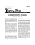
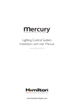
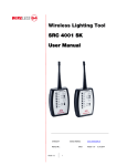
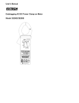
317/319 Clamp Meter Users Manual PN 4092877 September 2011 © 2011 Fluke Corporation. All rights reserved. Specifications subject to change without notice. All product names are trademarks of their respective companies. LIMITED WARRANTY AND LIMITATION OF LIABILITY This Fluke product will be free from defects in material and workmanship for one year from the date of purchase. This warranty does not cover fuses, disposable batteries, or damage from accident, neglect, misuse, alteration, contamination, or abnormal conditions of operation or handling. Resellers are not authorized to extend any other warranty on Fluke’s behalf. To obtain service during the warranty period, contact your nearest Fluke authorized service center to obtain return authorization information, then send the product to that Service Center with a description of the problem. THIS WARRANTY IS YOUR ONLY REMEDY. NO OTHER WARRANTIES, SUCH AS FITNESS FOR A PARTICULAR PURPOSE, ARE EXPRESSED OR IMPLIED. FLUKE IS NOT LIABLE FOR ANY SPECIAL, INDIRECT, INCIDENTAL OR CONSEQUENTIAL DAMAGES OR LOSSES, ARISING FROM ANY CAUSE OR THEORY. Since some states or countries do not allow the exclusion or limitation of an implied warranty or of incidental or consequential damages, this limitation of liability may not apply to you. Fluke Corporation P.O. Box 9090 Everett, WA 98206-9090 U.S.A. 11/99 Fluke Europe B.V. P.O. Box 1186 5602 BD Eindhoven The Netherlands Table of Contents Title Page Introduction............................................................ 1 How to Contact Fluke............................................. 1 Safety Information.................................................. 2 Symbols................................................................. 5 Specifications......................................................... 6 General Specifications....................................... 6 Electrical Specifications..................................... 7 Software Specifications................................... 10 Environmental Specifications.......................... 10 The Product......................................................... 11 i 317/319 Users Manual ii Clamp Meter Introduction The Fluke 317 and 319 are hand-held, battery-operated clamp meters (the Product) that measure: • ac and dc current • ac and dc voltage • resistance • continuity • frequency The Product ships with: • test leads • soft case • three AAA batteries (installed) • 317/319 User Manual How to Contact Fluke To • • • • • • • contact Fluke, call one of these telephone numbers: Technical Support USA: 1-800-44-FLUKE (1-800-443-5853) Calibration/Repair USA: 1-888-99-FLUKE (1-888-993-5853) Canada: 1-800-36-FLUKE (1-800-363-5853) Europe: +31 402-675-200 Japan: +81-3-6714-3114 Singapore: +65-738-5655 Anywhere in the world: +1-425-446-5500 1 317/319 Users Manual Or, visit Fluke’s website at www.fluke.com. To register your product, visit http://register.fluke.com. To view, print, or download the latest manual supplement, visit http://us.fluke.com/usen/support/manuals. Safety Information XWarning To prevent possible electrical shock, fire, or personal injury: • Use the Product only as specified, or the protection supplied by the Product can be compromised. • Limit operation to the specified measurement category, voltage, or amperage ratings. • Do not touch voltages >30 V ac rms, 42 V ac peak, or 60 V dc. • Carefully read all instructions. • Do not exceed the Measurement Category (CAT) rating of the lowest rated individual component of a Product, probe, or accessory. • Do not use the Product around explosive gas, vapor, or in damp or wet environments. • Use only correct measurement category (CAT), voltage, and amperage rated probes, test leads, and adapters for the measurement. • Do not work alone. 2 Clamp Meter Safety Information • Do not apply more than the rated voltage, between the terminals or between each terminal and earth ground. • Comply with local and national safety codes. Use personal protective equipment (approved rubber gloves, face protection, and flame-resistant clothes) to prevent shock and arc blast injury where hazardous live conductors are exposed. • Replace the batteries when the low battery indicator shows to prevent incorrect measurements. • Keep fingers behind the finger guards on the probes. • Measure a known voltage first to make sure that the Product operates correctly. • Do not use and disable the Product if it is damaged. • Connect the common test lead before the live test lead and remove the live test lead before the common test lead. • Read all safety Information before you use the Product. • Remove all probes, test leads, and accessories that are not necessary for the measurement. • Before each use, examine the Product. Look for cracks or missing pieces of the clamp housing or output cable insulation. Also look for loose or weakened components. Carefully examine the insulation around the jaws. 3 317/319 Users Manual • Do not use test leads if they are damaged. Examine the test leads for damaged insulation, exposed metal, or if the wear indicator shows. Check test lead continuity. • Disconnect power and discharge all high-voltage capacitors before you measure resistance, continuity, capacitance, or a diode junction. • Do not hold the Product anywhere above the tactile barrier. See Figure 1. • Do not use the current sensor if the wear indicator in the jaw opening is not visible. See Figure 2. For safe operation and maintenance of the product: • Remove batteries to prevent battery leakage and damage to the Product if it is not used for an extended period. • Be sure that the battery polarity is correct to prevent battery leakage. • Repair the Product before use if the battery leaks. • Have an approved technician repair the Product. • Remove the input signals before you clean the Product. • Do not operate the Product with covers removed or the case open. Hazardous voltage exposure is possible. 4 Clamp Meter Symbols Symbols Table 1 shows the symbols used in this manual or on the Product. Table 1. Symbols Symbol Explanation Risk of danger. Important information. Refer to manual. Hazardous voltage. Risk of electric shock. Application and removal from hazardous live conductors permitted. Double insulated Low battery Earth ground Alternating current Direct current Do not dispose of this product as unsorted municipal waste. Go to Fluke’s website for recycling information. Conforms to relevant European Union directives. CAT III Equipment is designed to protect against transients in equipment in fixed equipment installations, such as distribution panels, feeders and short branch circuits, and lighing systems in large buildings. 5 317/319 Users Manual Specifications General Specifications Digital Display������������������������ 6000 count resolution Low Battery Indication������������ Shows when the batteries are below their required voltage Power Source������������������������� Three AAA IEC LR03 batteries Clamp Opening Size�������������� 37 mm (1.45 in) Jaw Diameter������������������������� 37 mm (1.45 in) Dimensions (L x W x H)���������� 162.4 x 58.25 x 30.5 mm (6.39 x 2.29 x 1.20 in) Weight������������������������������������ Approximately 384 g (13.5 oz) (batteries included) Display Resolution����������������� 6000 Counts Auto Range���������������������������� Available in Ohms Safety������������������������������������� CE, EN/IEC 61010-1 and IEC 61010-2-032 Measurement Category���������� 600 V CAT III 6 Clamp Meter Specifications Electrical Specifications The accuracy specification is defined as ±(% reading + digits) at 23 °C ± 5 °C. Function Parameter 317 319 Range 40.00 A 600.0 A 40.00 A 600.0 A 1000 A Resolution 0.01 A 0.1 A 0.01 A 0.1 A 1 A Accuracy 1.6 % ±6 digit (50-60 Hz) [40 A] 2.5 ±8 digit (60-500 Hz) [40 A] 1.6 % ±6 digit (50-60 Hz) [40 A] 2.5 ±8 digit (60-500 Hz) [40 A] 1.5 % ±5 digit (50-60 Hz) [600 A] 2.5 ±5 digit (60-500 Hz) [600 A] 1.5 % ± 5 digit (50-60 Hz) [600/1000 A] 2.5 ±5 digit (60-500 Hz) [600/1000 A] Crest factor add 2 % into spec for CF >2 3.0 Max @ 500 A 2.5 Max @ 600 A 3.0 Max @ 500 A 2.5 Max @ 600 A 1.4 Max @ 1000 A AC response rms rms (A ac) 7 317/319 Users Manual Function Parameter 319 40.00 A 600.0 A 40.00 A 600.0 A 1000 A Resolution 0.01 A 0.1 A 0.01 A 0.1 A 1 A Accuracy 1.6 % ±6 digit [40 A] 1.5 % ±5 digit [600 A] 1.6 % ±6 digit [40 A] 1.5 % ±5 digit [600/1000 A] Range 600.0 V Resolution 0.1 V (V ac) Accuracy 1.5 % ±5 digit (20-500 Hz) AC response rms Range 600.0 V Resolution 0.1 V Accuracy 1 % ±4 digit Range 400.0 Ω 4000 Ω Resolution 0.1 Ω 1 Ω Accuracy 1 % 5.0 (A dc) (V dc) Ω ≤30 Ω Inrush 8 317 Range Integration Time N/A 100 ms Clamp Meter Specifications Function Hz Parameter 317 319 Range N/A 5.0 - 500.0 Hz Accuracy N/A 0.5 % ±5 digit Trigger Level N/A 10 – 100 Hz ≥5 A, 5 – 10 Hz, 100 – 500 Hz ≥10 A The accuracy specifications apply at 23 °C ± 5 °C (73 °F ±41 °F) Below 18 °C and above 28 °C (64 °F and above 82 °F) accuracy degrades at (0.1) times specification per °C. True rms for ac V and ac A accuracy is specified from 5 % to 100 % of range. 9 317/319 Users Manual Software Specifications Calibration������������������������������ Full manual calibration and test One-year calibration cycle Data Integrity and Security����� Calibration parameters stored in flash ROM. Environmental Specifications Operating Temperature����������� -10 °C to 50 °C (14 °F to 122 °F) Storage Temperature�������������� -40 °C to 60 °C (-40 °F to 140 °F) Operating Humidity����������������� Non condensing <10 °C (<50 °F) 90 % RH (50 °F to 86 °F) (10 °C to 30 °C) 75 % RH (86 °F to 104 °F) (30 °C to 40 °C) 45 % RH (104 °F to 122 °F) (40 °C to 50 °C) (Without Condensation) Operating Altitude������������������� 2000 meters (1 mile) above mean sea level Storage Altitude���������������������� 12,000 meter (7 miles) above mean sea level IP Rating�������������������������������� IP40 Vibration Requirements���������� Random MIL-PRF-28800F Class 2, 5-500 Hz, 30 minutes per axis Drop Test Requirements��������� 3 ft (1 m) drop test, six sides, oak floor EMI, RFI, EMC����������������������� Instrument unspecified for use in EMC field ≥0.1 V/m 10 Clamp Meter The Product The Product 1 ClampMeter 600 V 1000 A 600 A 1000 A Tactile Barrier 40 A V OFF HOLD VA Hz MAXMINAVG ZERO ACDC MIN MAX INRUSH 319 TRUE RMS CLAMP METER CAT 600 V COM V etr111.eps 11 317/319 Users Manual 2 Jaw Wear Jaw Wear Indicator 3 A 60 600 V 1000 A 00 10 0V 60 00 A 10 A 0A 1000 A 40 A 600 A 1000 A Hz F OF 600 A Hz V 40 A RO A ZE RU IN S P M ET M T V CA 0 60 9 31 IN M AX M CLA M CO RM SH UE TR V LD HO 40 A ER V OFF HOLD A ZERO MIN MAX INRUSH 319 TRUE RMS CLAMP METER ZERO CAT 600 V COM V etr113.eps 12 Clamp Meter The Product 4 V 600 A 1000 A Hz V 40 A V OFF HOLD V ZERO MIN MAX INRUSH 319 TRUE RMS CLAMP METER CAT 600 V ZERO COM V etr114.eps 13 317/319 Users Manual 5 40 A V OFF HOLD ZERO MIN MAX INRUSH 319 TRUE RMS CLAMP METER CAT 600 V COM V <30 6 600 A 1000 A Hz 40 A V OFF etr116.eps 14 Clamp Meter The Product 7 Display Hold 600 A 1000 A Hz HOLD 40 A V V OFF HOLD V 8 MIN MAX AVG 600 A 1000 A Hz MIN MAX 40 A = 1x MIN MAX V OFF HOLD = 2x MIN MAX V = 3x MIN MAX ZERO INRUSH MIN MAX 2 sec = Exit 319 SC etr122.eps 15 317/319 Users Manual 9 A Off 3 A On 600 V 1000 A 600 A 1000 A Hz 1 40 A V OFF HOLD ZERO 319 TRUE RMS CLAMP METER CAT 600 V COM 600 A MIN MAX INRUSH V 100 ms 600 V 1000 A A INRUSH 1000 A Hz 40 A 2 V OFF HOLD 4 A ZERO MIN MAX INRUSH 319 TRUE RMS CLAMP METER A AC CAT 600 V COM V etr119.eps 16 Clamp Meter The Product 10 etr123.eps 17 317/319 Users Manual 18