1
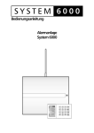
2.9 Subsystem arming 3.2 User codes setting In a large building a sub control panel can be enrolled to the JA-63. The subsystem reports all alarms and failures to the main system. The installer can program if the systems will be armed and disarmed separately (by their own codes and remote controls) or if the main control panel will rule the sub control panel. Ask your installer for explanation on how to operate your system if a sub control is panel installed. There can be up to 14 different user codes for individual users. The system stores to its memory which code was used for what event and when. This data can go to a Central monitoring station as well and can also be viewed by a PC with Comlink software. All user codes are empty as a factory default and the supervisor should program them entering: F 6 2.10 Appliance control xxxx yy zzzz The system can be used to control an electrical appliance (light, heating, ventilation etc.). In such a case users can operate the device: Locally with keypad* – entering F81 (ON) or F80 (OFF). Remotely by phone keypad or by SMS messages – the control panel must be equipped with GSM communicator for this feature where xxxx is the master code, yy is the user code index (from 01 to 14) and zzzz is the new user code. * To delete a particular user code, enter 0000 as the new code (combination 0000 can not be used as a valid code). Installer can program that this feature will work only when the entry is followed by a user code. 3 User’s settings Following section is designated for the system supervisor, who knows the master code. All programming sequences can be terminated before completed (by N key). 3.1 New master code The master code is used by the supervisor. The factory default master code is 1234 and you should program your own four digits code. Code programming is only possible when the system is disarmed. To change an existing master code enter: F 5 xxxx yyyy yyyy where xxxx is the existing and yyyy is the new master code (new code must be entered twice to avoid an error). Example: Existing code 1234 will change to 6723 entering: F 5 1234 6723 6723 Example: If the master code is 1234 and the user 3 new code should be 5277 enter: F 6 1234 03 5277 Example: If the master code is 1234 the user 3 code can be deleted by: F 6 1234 03 0000 Notes: • You can program new codes only when the system is disarmed. • The supervisor should record the codes to the table on last page of this manual (it should be kept hidden in a safe place). • • If the system is split, the supervisor can change the user codes, but can not change to which section the particular code belongs (only the installer can change this). 3.3 Internal clock setting The control panel has a built in real time clock. All events are stored to the event memory including the time & date. The clock should be set after installation, but the supervisor can set the clock while in the user mode. To switch the control panel to the user mode enter F 0 master code. User mode will be indicated by a U on the keypad. To set the clock enter: 4 hh mm DD MM YY where: hh = hours; mm = minutes; DD = day; MM = month and YY = year Example: at 21:30 on March 19. 2005 enter: 4 21 30 19 03 04 To exit user mode press N. Alarm system JA-63 „Profi“ -8- MGK51503 Alarm system JA-63 „Profi“ -9- MGK51503 3.4 Automatic arming / disarming 2.5 Home arming The system can automatically arm and disarm for a requested period of a day. While in the user more, up to ten instructions (time & action) can be programmed in the period of one day. To switch the control panel to the user mode enter F 0 master code. User mode will be indicated by a U on the keypad. To program automatic arming enter: The installer can program particular detectors so that they will be automatically bypassed in the so called “Home” partial arming. This allows for people to stay in the particular part of the house after arming. To arm partially: 64 n a hh mm where: n = instruction number from 0 to 9 a = action (see the actions' table) hh = hours (from 00 to 23) mm = minutes (from 00 to 59) Example: to program an automatic complete arming of the system at 21:15 everyday enter: 64 0 1 21 15 Actions' table a no splitting 0 no action 1 arm all 2 disarm 3 partial arming 4 partial arming 5 disarm 6 disarm split no action arm all disarm all arm A arm B disarm A disarm B To disarm a partially armed system - enter your user code or press the button on the remote control. or 2.6 Door opening An electrical door lock (if installed) can be controlled via the alarm system. • Press the door opening button on the keypad to release the lock. 2.7 Alarm memory reading To exit user mode, press the N key. 3.5 Bypass The supervisor can bypass (switch off) particular zones (potential sources of alarms) while in the user mode. If a zone is bypassed, it can’t trigger an alarm. To switch the control panel to the user mode enter F 0 master code. User mode will be indicated by a U on the keypad. To set up bypass: 1. Press key 1 to open the bypass menu. 2. With key 1 and 7 you can scroll all potential alarm sources (wireless detectors are distinguished with the symbol ). 3. Select the source (detector, wired input…) which you want to bypass and: a. either press key 2 for 2 seconds to bypass the source for the next arming period (confirmed by flashing Battery LED); b. or press key 3 for 2 seconds to bypass the source permanently (confirmed by the Battery LED being permanently lit); - 10 - On the keypad press home arming button H will indicate the Home partial arming on the keypad. Notes: • If any automatic action is selected, it will be preformed everyday at the programmed time, following the internal control panel clock. • The automatic arming and disarming can be overridden manually anytime (by a user code or a remote control) • If the control panel is in the requested arming mode before the action time, the programmed action will not change the arming • Factory default setting - all instructions are set for no action Alarm system JA-63 „Profi“ • MGK51503 All events (arming, disarming, alarms, failures…) are recorded into the control panel’s memory along with the time and date. The complete system history can be viewed using a PC with Comlink software. Alarms and failures can also be viewed on the keypad by entering: F 4 - will show the last recorded alarm or failure. Press key 4 multiple times to go deeper in to the memory. 2.8 Split system arming The system can be split by the installer into two independent sections (A,B) and a shared section (corridors, stairs, a main door…). This allows for a particular user to arm and disarm only a particular section of the house with his/her code or remote control (exactly as in a non split system). Arming of sections A and B is indicated by I I symbols on the keypad. The shared section will be armed automatically when A and B sections are both armed. With the master code the supervisor can arm and disarm both sections. If the master code is entered, the system will arm (if completely disarmed) or disarm (if any section is armed). Entering F1 master code will control only section A and F2 master code only section B (this is true only when fast arming is disabled by the installer). Note: partial Home arming is not possible if the system is split. Alarm system JA-63 „Profi“ -7- MGK51503 c. 2.2 Disarming On the keypad - enter your user code On the remote control (RC-4x) – press the • button • system will beep twice • if there are 3 beeps, important information is indicated and will be displayed on the keypad. Examples: o FAILURE LED is flashing – press the N key to view the cause o ALARM LED and zone number is flashing = alarm in the memory. Be careful and check the house. • if you enter the premises when the system is armed, the entrance delay countdown will start after you trigger a delayed detector (ARM LED will flash and beeps will sound if programmed so*). • • • multiple pressing and holding of the keys (2 or 3) will switch the bypass on – off – on – off … 4. By repeating step 3. you can bypass all required alarm sources. To close the Bypass menu press the N key. If anything is bypassed when arming, four beeps will sound and b will be displayed on the keypad during the exit delay (and partial arming will be recorded to the memory). All bypasses selected with key 2 (next arming period bypasses) will switch off automatically with the first following disarming. The existing bypass setting can be checked or modified in the bypass menu. All bypasses can be deleted by key 4 in the bypass menu. They can also be deleted by the programming mode opening or if the control panel is disconnected from the power completely (AC & back up battery). To exit user mode press N. 4 Digital communicator 2.3 Panic Alarm 4.1 JA-60GSM Dialer module If you are in danger you can trigger the silent panic alarm to inconspicuously call for help. While in Panic alarm mode the control panel can send a voice message, an SMS message and data to a central monitoring station via a telephone line (depends on installation settings). If the control panel is equipped with a JA-60GSM communicator, please look at the JA-60GSM user manual for details about user’s setting. Panic alarm can be triggered: If the control panel is equipped with a JA-65X telephone communicator and if the installer enabled the supervisor to modify the communications settings, only then will the following programming be possible. • On the keypad - press the panic key and then enter your access code. and buttons On the remote control (RC-4x) - press the simultaneously. The remote control can be switched (by installer) to a Panic mode, in which pressing of any button will trigger the Panic alarm. • By pressing this large sized panic button, the RC-22 (can be installed on the wall, under a desk etc.). 2.4 To stop ALARM • Sending of voice and SMS messages will cease after the alarm is stopped. All corresponding report codes (alarm triggering & stopping) will be sent to the central monitoring station. If user does not stop the alarm, it will stop automatically after the programmed period and the alarm memory indicator will activate. The control panel will return to the same mode as before the alarm. Alarm system JA-63 „Profi“ 4.2.1 Telephone numbers for voice message sending Up to 4 telephone numbers can be programmed in the user mode. To switch the control panel to the user mode enter F 0 master code. User mode will be indicated by a U on the keypad. Store telephone numbers for voice message by entering: 7 xx... xx F y If an alarm is triggered when you are present, you can stop it by entering your access on the remote control. code or by pressing button • 4.2 JA-65X Telephone communicator -6- MGK51503 where xx...xx = telephone number y = memory number from 1 to 4 A telephone number can have a maximum of 16 digits. A dialing pause can be entered with F0 Note: enter a pause (F0) after the last digit of a number, which is calling a mobile phone. This way the number will be called only once and the dialer will not check the line signals (some mobile phone systems do not generate standard telephone line signals). Alarm system JA-63 „Profi“ - 11 - MGK51503 Example: to store tel. number 0 123456 to memory no. 2 enter: 7 0 F0 12345 F2 To delete a telephone number enter: 7 F0 Fy where y is a memory number from 1 to 4 Factory default master code is 1234. The supervisor should change it after installation. To exit user mode, press the N key. 4.2.2 Master code Is an extra (15th) access code for the supervisor. It can operate the system and it also allows for the programming of the other user codes and to enter the user mode (see section 3). Telephone communicator testing Testing is possible in the user mode. To switch the control panel to the user mode enter F 0 master code. User mode will be indicated by a U on the keypad. Entering 89 will cause the communicator to send voice message number 2 to all programmed telephone numbers. It will also send an SMS message if programmed (see section 0). The telephone line signals will be audible from the control panel’s built in speaker during the test (if the dialer is triggered by an alarm in normal operation, it will call silently). Testing can be terminated with the N key. Service code Is an extra code, used by the installer to enter the programming mode. End users are not usually told this code. If an invalid access code is entered more than four times in a given period of time, it will trigger a Tamper alarm on the control panel. 2.1 Arming On the keypad - enter your user code or press the fast arming button*. On the remote control (RC-4x) – press the Notify the people who will be called before testing! • • • To exit user mode, press the N key. 5 System testing The supervisor should test the system monthly. For testing the control panel should be in the user mode. Enter F0 master code to switch to the user mode (U will be indicated on the keypad). No alarm can be triggered while in the user mode and any triggering of a detector, a remote control or a panic button will be indicated on the keypad. Note: some detectors (for example the wireless motion detector) in normal mode can not send the next triggering information until 5 minutes after the previous triggering was sent. It is possible to switch such a detector to the testing mode by opening and closing its cover. See the particular product manual for more details. If anything does not work during testing, call the installer. button system will beep once and the exit delay countdown will start ARMED indicator will flash during exit delay** you should leave the protected area within the duration of the exit delay If there are 4 beeps while arming, the system is indicating an unusual situation and the keypad will display the specific information: ALARM and a zone number – the zone is not ready (opened door etc.), check the indicated item. b – some detectors are bypassed (done by supervisor, see part 3.5) Note: supervisor can program an automatic arming for a desired time (for example, the house will be armed automatically at 21:00 if left disarmed). Automatic disarming is also programmable. See part 3.4 for details. To exit user mode press N. 6 Battery replacement All the battery-powered items perform regular battery testing. If the lifetime of the battery is near the end, the system will indicate the need for battery replacement (Battery indicator and the item address will be shown on the keypad). When any detector or keypad asks for new batteries, they should be replaced in a week. To replace batteries either call the installer or do the following: • switch the control panel to the user mode (entering F0 master code) Alarm system JA-63 „Profi“ - 12 - MGK51503 * Fast arming (without access code) can be disabled by the installer The JA-60F battery powered wireless keypad will stop indications 10sec after the most recent key entry. ** Alarm system JA-63 „Profi“ -5- MGK51503 communication failure indicated event (Tamper or Failure) was caused by the telephone line indicated event (Tamper or Failure) was caused by a device (keypad or PC) connected to the digital bus wireless keypad lost connection with the control panel error self testing error – call installer Telephone line digital bus tab. 1 88 display specifies mode of the control panel: user mode authorized supervisor can test, bypass zones, change batteries, record voice messages, program tel. numbers and adjust internal clock in this mode home arming system is partially armed – particular detectors are bypassed (someone remains in the house) A section armed A section is armed (split system) B section armed B section is armed (split system) complete arming system is completely armed bypass warning that some detectors are bypassed – indicated while arming key pressed waiting for more data to complete the entry programming mode for installer programming and testing • • • • open the cover of the detector (keypad) replace its batteries with new ones (use only corresponding size and good quality alkaline batteries). Wait for approximately 20 seconds before inserting batteries close the device’s cover and test its function. to exit User mode, press the N key on the keypad Note: normal battery life in wireless items is about 1 year. Exposure to a very cold temperature, frequent triggering or low initial battery capacity can shorten the battery life. Recommendations: the system should be annually inspected by a professional installer. The control panel and the outdoor siren back up batteries should be replaced with new ones after 5 years. 7 Enrollment of the control panel to UC-2xx modules The wireless control panel can send data to UC–216, UC–222 and UC-260 output modules. To enroll the JA-63 control panel to the UC-2xx: • • • • switch the control panel to the user mode (entering F0 master code) switch the UC-2xx to learning mode (see its manual) enter 299 on the alarm system keypad – the control panel will enroll press the N key on the keypad to exit User mode, tab. 2 2 Controlling the system The system can by controlled by keypads, remote controls or by a PC with the Comlink Software. User codes Can be used to arm and disarm the system or to reset an alarm. There can be up to 14 different user codes for individual users. The system stores to its memory which code was used for which operation as well as the time &date of usage. This data can go to a Central monitoring station and can also be viewed using a PC with Comlink software. All user codes are empty as a factory default and should be programmed by the supervisor (see section 3.2). Alarm system JA-63 „Profi“ -4- MGK51503 Alarm system JA-63 „Profi“ - 13 - MGK51503 User codes and controllers code index section user name A Note: features of this system can be substantially modified by programming during installation. The installer should instruct the users how to operate and test the system. notes B Master code - supervisor 0. 1. 2. 3. 4. 5. 6. 7. 8. 9. 10. 11. 12. 13. 14. c1 c2 c3 c4 c5 c6 c7 c8 1 Indicators The alarm system’s status is indicated on the keypad. There can be multiple keypads in the system and in such a case all keypads will have identical functions. A keypad’s LED indicators and display inform the user about the conditions of the system. LED indicators: Alarm: alarm triggered by an intruder, smoke, gas etc Tamper: opened cover, damaged detector, excessive number of attempts to enter code, etc. Fault: power loss, lost communication with a detector etc., (view details by pressing N) Battery: battery of the device specified on the display is low. See battery replacement section. information received from a wireless item or wireless communication of the keypad in progress Armed: continues = armed, slow blinking = exit delay, fast blinking = entrance delay Power: continues = AC power & back up battery O.K., blinking = failure (AC or back up battery), off = control panel is not powered 88 display specifies event source: Telephone communicator setting memory calling to tel. number 1. 2. 3. 4. 5. wireless detector 12 notes wired zone 2 wireless controller 3 Pager Timers exit delay entrance delay alarm duraton sec sec min Notes: Alarm system JA-63 „Profi“ - 14 - MGK51503 Alarm system JA-63 „Profi“ indicated event (Alarm, Tamper, Failure or Battery) was caused by detector number 12 indicated event (Alarm, Tamper, Failure or Battery) was caused by wired zone number 2 indicated event was caused by wireless controller (remote control, keypad, Panic button) number 3 Control panel indicated event (Tamper or Failure) was caused by the control panel Wireless siren indicated event (Tamper, Failure or Battery) was caused by the outdoor wireless siren Sub control panel indicated event (Alarm, Tamper, Failure or Battery) was caused by the sub control panel -3- MGK51503 Detectors Contents: Indicators .................................................................................................................... 3 Controlling the system............................................................................................... 4 2.1 Arming .................................................................................................................. 5 2.2 Disarming ............................................................................................................. 6 2.3 Panic Alarm .......................................................................................................... 6 2.4 To stop ALARM .................................................................................................... 6 2.5 Home arming........................................................................................................ 7 2.6 Door opening........................................................................................................ 7 2.7 Alarm memory reading ......................................................................................... 7 2.8 Split system arming .............................................................................................. 7 2.9 Subsystem arming................................................................................................ 8 2.10 Appliance control.................................................................................................. 8 3 User’s settings............................................................................................................ 8 3.1 New master code ................................................................................................. 8 3.2 User codes setting................................................................................................ 9 3.3 Internal clock setting............................................................................................. 9 3.4 Automatic arming / disarming ............................................................................. 10 3.5 Bypass ............................................................................................................... 10 4 Digital communicator............................................................................................... 11 4.1 JA-60GSM Dialer module................................................................................... 11 4.2 JA-65X Telephone communicator ...................................................................... 11 4.2.1 4.2.2 5 6 7 Telephone numbers for voice message sending .............................11 Telephone communicator testing .....................................................12 System testing .......................................................................................................... 12 Battery replacement ................................................................................................. 12 Enrollment of the control panel to UC-2xx modules ............................................. 13 position detectors type location in the house reaction* section A B S 1. 2. 3. 4. 5. WIRELESS DETECTORS 1 2 6. 7. 8. 9. 10. 11. 12. 13. 14. 15. WIRED INPUTS 16. 1. 2. 3. 4. * Alarm system JA-63 „Profi“ -2- MGK51503 I – instant D – delayed F – fire P – panic Alarm system JA-63 „Profi“ - 15 - T – tamper N – next delayed MGK51503 Notes: Alarm system JA-63 „Profi“ JA-63 „Profi“ User manual - 16 - MGK51503