1
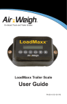
On-Board Truck and Trailer Scales
LoadMaxx Tractor System
User Guide
PN:901-0114-001 R3
Contents
LoadMaxx Tractor Overview..........................................................1
Navigating the Scale Menu..................................................................1
Calibrating and Setting Up Scale..................................................2
Checking Your Model Number.............................................................2
Determining Calibration Based On Trailer Setup..............................3
Calibration and Fifth Wheel Positioning...............................3
Tractor with a Lift Axle............................................................4
Tractor using Drop-and-Hook Trailer Applications.............4
Tractor with a Trailer Direct Connection...............................4
Calibrating Your Scale...........................................................................5
Calibrating a Lift Axle............................................................................8
Lift Axle Heavy Weight Worksheet.......................................9
Calibrating by Using Ratio and Offset...............................................10
Adjusting a Calibration........................................................................12
Adjust Calibration Worksheet..............................................14
Configuring a Full Trailer.....................................................................15
Truck and Full Trailer Configuration....................................15
A-Train Configuration............................................................16
Tractor, Trailer Direct, Full Trailer Configuration................18
Using LoadMaxx Tractor System.................................................19
2
Weighing Your Load............................................................................19
Navigating the Weight Display...........................................................20
Clearing the Net Weight.......................................................21
Returning to the Weight Display..........................................21
Setting a PIN........................................................................................22
Installing and Activating Overweight Alarms...................................23
Installing Alarms....................................................................24
Activating Warnings and Alarms.........................................25
Programming Alarm Delays................................................26
Programming Alarm Logic ..................................................27
Setting Other Alarm Options...............................................28
Changing the Model Number.............................................................29
Activating an Inclinometer..................................................................30
Changing Display Features................................................................31
Changing the Display Text Size..........................................31
Changing the Display Language.........................................32
Setting the Display Backlight...............................................33
Setting the Date and Time...................................................34
Setting the Weight Units......................................................35
Show or Hide Information from Weight Display................36
Printing Weight Data...........................................................................37
Streaming Weight Data......................................................................38
Troubleshooting Your Scale.........................................................39
Navigating the Diagnostics Menu.....................................................39
Diagnostics Menu Options..................................................40
Weight Readings Are Inaccurate......................................................41
Weight Readings Fluctuate................................................................42
Weight Readings Do Not Change.....................................................43
Weight Readings Are Always Zero...................................................45
Scale Won’t Turn On...........................................................................46
What to Do if you Forget Your PIN....................................................47
Identifying the Causes of Error Messages......................................48
Limited Warranty...........................................................................49
Procedure For Warranty Claims..................................................50
LoadMaxx Tractor Overview | Navigating Scale Menu
Section 1
LoadMaxx Tractor Overview
The LoadMaxx tractor scale calculates the weight of each axle
group (accurate to within 300 pounds or 140 kilograms) and displays
weights in the truck cab in 20-pound or 20-kilogram increments.
A LoadMaxx tractor scale can also read weight measured by a
LoadMaxx trailer scale installed on your trailer. The trailer scale
transmits weight data through the vehicle’s existing J-560 cord to
the tractor, so you can read trailer weights inside the cab. LoadMaxx
works using sensors that measure air pressure changes in the
trailer’s suspension; it then converts those numbers into weight.
The LoadMaxx cab display can show up to nine axle groups on one
tractor/trailer combination.
Navigating the Scale Menu
To illuminate the display: press any key one time.
To go back: push the ESC key to revert to the previous screen. Any
unsaved changes will be erased if you press ESC.
To select a menu item: use the up or down arrow keys ▲ or ▼
to highlight your chosen menu item. The item will flash when it is
highlighted. Choose OK to select the flashing item.
To save a change: Press the OK key.
To enter a numeric value: use the up or down arrow keys ▲ or ▼
to select the correct number. Press ENTER to save your value.
Main menu: Throughout this manual, the term “main menu” refers
to the top menu. This menu shows PRINT, ERASE / SETUP /
DIAGNOSTICS.
Weight display: This term refers to the scale’s default screen,
which shows axle weights and vehicle’s GVW and net weights.
1
Calibrating, Setting Up Scale | Determining Model #
Section 2
Calibrating and Setting Up Scale
You must calibrate your scale before you can use it to obtain
accurate weights. Once you have calibrated your scale and it reads
weight accurately, you will not have to recalibrate unless your
suspension changes or you move the position of your fifth wheel.
Checking Your Model Number
It is important that your LoadMaxx scale is programmed with the
correct model number before you begin calibration. Although scales
come pre-programmed with the model number requested during
purchasing, we recommend that you check the model number
again prior to calibration. To check your model number, follow the
instructions below.
1. Make sure your scale is installed properly. See the LoadMaxx
Tractor Installation Guide for more information.
2. Turn on your vehicle’s ignition. Your LoadMaxx display should
light up and read AIR-WEIGH. After a moment the screen
will show LOADMAXX and, below that, the four-digit model
number.
3. Consult insert 901-0039-000, available with your truck kit
or online at www.air-weigh.com, to determine if the model
number that displays is correct for your tractor and trailer
setup.
2
Calibrating, Setting Up Scale | Trailer Setup
Determining Calibration Based On Trailer Setup
Calibration procedure will vary depending on your tractor and trailer
setup. Common scenarios are addressed below; if your tractor and
trailer setup does not conform to any of these, contact Air-Weigh
Support for further information.
Calibration and Fifth Wheel Positioning
If your tractor scale has sensors installed on both the front and
rear axles, the position of the fifth wheel does not affect calibration
and it can be moved after calibration without affecting weight
readings. However, many models of LoadMaxx tractor scales use
a calculation to determine the weight of the front (steer) axle and
only require a sensor to be installed on the back (drive) axle. If this
is the case for your vehicle, you can NOT move the fifth wheel after
calibration without affecting weight readings. Consult insert 9010039-000 and, if necessary, inspect your steer axle to see if there is
a sensor installed.
If your LoadMaxx scale uses calculated steer, determine the best
position for the fifth wheel and move the fifth wheel to that position
before calibration. This should be the position that allows maximum
legal GVW or the position you use most often. If you need to move
the fifth wheel after calibration, you MUST recalibrate the LoadMaxx
scale.
3
Calibrating, Setting Up Scale | Trailer Setup
Tractor with a Lift Axle
If your LoadMaxx scale is programmed with one of the following
model numbers, see the section entitled Calibrating a Lift Axle.
583358345835
5836 5864 5838 5839
Otherwise, calibrate your scale with the lift axle up.
Tractor using Drop-and-Hook Trailer Applications
The LoadMaxx tractor scale will read the weights of any connected
trailer that has a LoadMaxx trailer scale installed through the J560
cable. The calibration procedure is as follows: choose any trailer
and connect it to the tractor. Calibrate the empty weight when the
trailer is empty and the heavy weight when the trailer is loaded to
full capacity. Once the trailer scale has been calibrated, any tractor
equipped with LoadMaxx can connect to this trailer without needing
to recalibrate.
Tractor with a Trailer Direct Connection
The trailer direct setup allows you to measure the weight of a
semitrailer or full trailer that is used in a dedicated tractor/trailer
setup with just the LoadMaxx tractor scale. In order to do so, you
must order Model #5851, which includes additional cables and air
sensors for the trailer. The calibration procedure for a trailer direct
setup is the same as with a drop-and-hook application; however, if
you disconnect the tractor and trailer for any reason and re-connect
them you must then re-calibrate the trailer.
4
Calibrating, Setting Up Scale | Calibrating Your Scale
Calibrating Your Scale
When you are calibrating your LoadMaxx scale, you can collect
and enter either the heavy weight or empty weight first. This guide
provides instructions for entering the heavy weight before the empty
weight, but either order is permissible. However, your trailer MUST
be empty when you enter the empty axle weights into the scale, and
fully loaded when you enter the heavy axle weights.
Follow the instructions below to collect and enter weight data.
1. Connect a trailer to the truck you are calibrating.
2. Fill the trailer to maximum legal GVW, or as close as
possible. Filling the trailer only half-full will lead to a less
accurate calibration.
3. Fill your tank with fuel.
4. Proceed to a certified in-ground scale. Record axle weights
for your tractor. If the scale does not have separate weighing
mechanisms for each axle, drive the truck so that only the
front (steer) axle is on the scale and record the weight, then
repeat for the rear (drive) axle. It is important that the platform
scale is as level as possible if you are using this method;
otherwise, weights will not be accurate. If you have a lift axle,
make sure that it is raised while you are measuring axle
weights.
5. Park on level ground. Leave your engine
running.
6. Release all brakes, including trailer
brakes. Leave the vehicle in neutral.
Fig. 1. Main Menu
5
Calibrating, Setting Up Scale | Calibrating Your Scale
7. If possible, deflate the suspension for 5
to 10 seconds, then re-inflate to factory
ride height.
8. Enter the heavy weight into the scale.
• Turn the vehicle on. Press ESC to
access to the main menu (Fig. 1).
Fig. 2. Print, Setup
• Press ▼ until PRINT, SETUP is
flashing (Fig. 2). Press ENTER.
• Press ▼ until SYSTEM SETUP is
flashing (Fig. 3). Press ENTER.
• CALIBRATION should be flashing
(Fig. 4). Press ENTER.
• Press ▼ until MANUAL CALIB is
flashing (Fig. 5). Press ENTER.
Fig. 3. Setup Menu
• Press ▼ until HEAVY WEIGHT is
flashing (Fig. 6). Press ENTER.
• The screen will read ENTER
HEAVY – VEHICLE MUST BE
HEAVY. After a few seconds the pick
axle menu will appear (Fig. 7).
Fig. 4. Sys Setup Menu
• STR should be flashing. Press
ENTER.
• Use ▲ or ▼ to enter the steer axle
heavy weight (Fig. 8) and press OK.
• The screen will read STEER HEAVY
WEIGHT (number you entered)
ACCEPTED. Press ESC to return to
the pick axle menu.
Fig. 5. Calibration Menu
• Press ▼ until DRV is flashing. Press ENTER.
6
Calibrating, Setting Up Scale | Calibrating Your Scale
• Use ▲ or ▼ to enter the heavy
weight of the drive axle and press
OK.
• The screen will read STEER
HEAVY WEIGHT (number you
entered) ACCEPTED. Press ESC
repeatedly until you return to the
main menu.
9. To collect and enter empty axle
weights, follow the instructions exactly
as above, but make sure your trailer
is completely empty. Select EMPTY
WEIGHT rather than HEAVY WEIGHT
from the manual calibration menu (Fig.
5) when entering the weights.
Fig. 6. Manual Cal Menu
Fig. 7. Pick Axle Menu
Fig. 8. Enter Weight
7
Calibrating, Setting Up Scale | Calibrating a Lift Axle
Calibrating a Lift Axle
If you have a LoadMaxx tractor scale with model number 5833,
5834, 5835, 5836, 5838, 5839, or 5864, see Guide 901-0117000, available on our website or by calling Air-Weigh Support. The
following calibration instructions assume that you have already
installed the sensor.
1. Make sure that empty and heavy calibration for the steer
and drive axles has been completed BEFORE you begin
calibrating the lift axle.
2. Raise the lift axle. Enter the empty weight of the lift axle as 0
pounds.
• Turn on the vehicle. From the weight display, press ESC
to reach the main menu. (See Figs. 1-7 for images of all
menus.)
• Press ▼ until PRINT, SETUP is flashing. Press ENTER.
• Press ▼ until SYSTEM SETUP is flashing. Press ENTER.
• CALIBRATION should be flashing. Press ENTER.
• Press ▼ until MANUAL CALIB is flashing. Press ENTER.
• Press ▼ until EMPTY WEIGHT is flashing. Press ENTER.
• The screen will read ENTER EMPTY – VEHICLE MUST
BE EMPTY. After a few seconds the screen will show the
pick axle menu.
• Press ▼ until LFT is flashing. Press ENTER.
• Use ▲ or ▼ until the weight reads 0. Press ENTER.
• The screen will read LIFT EMPTY WEIGHT 0 ACCEPTED.
Press ESC repeatedly until you return to the weight display.
8
Calibrating, Setting Up Scale | Calibrating a Lift Axle
• With the lift axle still raised, record the GVW from the
weight display. This is the no lift axle GVW.
3. Lower the lift axle. You should see the Steer and Drive
weights change on the weight display. Record the changed
weights in the worksheet below.
4. Add the changed Steer and Drive weights together in the
worksheet below. This is the steer drive sum.
5. Subtract the steer drive sum from the no lift axle GVW in the
worksheet below. The difference between them is the lift axle
heavy weight.
6. Follow the instructions in Step 2 to enter the heavy weight
into the scale. Make sure you select HEAVY WEIGHT from
the weight screen.
Lift Axle Heavy Weight Worksheet
No Lift Axle GVW (GVW with the lift axle
raised)______________
Steer weight with lift axle lowered: _______________________
Drive weight with lift axle lowered: _______________________
Add to obtain steer drive sum:
_____________________
Subtract steer drive sum from no lift axle GVW _________
This difference is the lift axle Heavy Weight.
9
Calibrating, Setting Up Scale | Ratio and Offset
Calibrating by Using Ratio and Offset
Calibration by ratio and offset allows you to save time when
calibrating a tractor that is identical to one you have already
calibrated. This can be useful with a large fleet adding multiple
trucks at once, but make sure that the truck you are calibrating has
exactly the same features as the truck you have already calibrated.
To calibrate using ratio and offset, follow the steps below.
1. Call Air-Weigh Support and ask for the manufacturer’s PIN,
required to enter ratio and offset values. Make sure you have
the serial number of the scale you plan to calibrate ready
to give to the Support staff; they will need it to find your
manufacturer PIN.
2. Turn on the vehicle that has already been calibrated. From
the weight display, press ESC to reach the main menu.
3. Press ▼ until PRINT, SETUP is flashing. Press ENTER.
4. Press ▼ until DIAGNOSTICS is flashing. Press ENTER.
5. Press ▼ until COMLINKS is flashing. Press ENTER.
6. Press ▼ until CALIB DATA is flashing. Press ENTER.
7. Press ▼ twice. The screen will show RATIO and OFFSET
for the steer axle. Record these values.
8. Press ▼ three more times. The screen will show RATIO and
OFFSET for the drive axle. Record these values.
9. Turn on the new vehicle to be calibrated. From the weight
display, press ESC to reach the main menu.
10.Press ▼ until PRINT, SETUP is flashing. Press ENTER.
11. Press ▼ until SYSTEM SETUP is flashing. Press ENTER.
10
Calibrating, Setting Up Scale | Ratio and Offset
12.Press ▼ until CALIBRATION is flashing. Press ENTER.
13.The screen will read MANUFACTURER PIN# NEEDED.
Enter the number you obtained in Step 1 from Air-Weigh
Support. Press ENTER.
14.Once the manufacturer’s PIN has been successfully entered,
the screen will show you two options: CALIB RATIO and
CALIB OFFSET.
15.Press ENTER to select ratio. The screen will read USE
CAUTION! PUSH ENTER TO CONTINUE. Press ENTER.
16. The screen will read PICK AXL: STR DRV. STR will be
flashing. Press ENTER.
17. Use the up and down arrows to enter the steer ratio and
press ENTER. The screen will read ACCEPTED! PLEASE
WAIT.
18.Press ESC to return to the previous menu. Use ▼ to select
DRV and press ENTER.
19.Use the up and down arrows to enter the steer ratio and
press ENTER. The screen will read ACCEPTED! PLEASE
WAIT.
20.Press ESC twice. Press ▼ to select CALIB OFFSET. Follow
the instructions listed from Steps 15 through 19, above, to
enter offset values for your LoadMaxx scale.
11
Calibrating, Setting Up Scale | Adjusting a Calibration
Adjusting a Calibration
Note: We do not recommend that you adjust a calibration
without first consulting Air-Weigh Support. Incorrect
adjustments can easily cause your scale to read inaccurately,
so be cautious when choosing to adjust a calibration. It is
almost always preferable to recalibrate your scale rather than
adjusting the calibration.
If your GVW is off by up to 1500 pounds consistently, and Support
advises use of the adjust function, follow the steps below.
1. Record the amount your GVW is consistently off in the
worksheet on p. 14.
2. Find the calibration weights that were entered when the scale
was first calibrated. Follow the steps below.
• From the weight display, press ESC to reach the main
menu.
• Press ▼ until PRINT, SETUP is flashing. Press ENTER.
• Press ▼ until DIAGNOSTICS is flashing. Press ENTER.
• Press ▼ until COMLINKS is flashing.. Press ENTER.
• Press ▼ until CALIB DATA is flashing. Press ENTER.
• Press ▼ once. You will see empty and heavy weight for
the steer axle. Record the heavy weight in the worksheet
below.
• Press ▼ three times. You will see empty and heavy
weight for the drive axle. Record the heavy weight in the
worksheet below.
12
Calibrating, Setting Up Scale | Adjusting a Calibration
3. Divide the steer axle heavy weight by the drive axle heavy
weight to find the steer/drive ratio. Record in the worksheet
below.
4. Multiply the steer/drive ratio by the amount the GVW is
consistently off to find the steer adjust value. Record in the
worksheet below.
5. Subtract the steer/drive ratio from 1. Multiply this value by the
amount the GVW is consistently off. This is the drive adjust
value. Record in the worksheet below.
6. Enter the adjustment into your LoadMaxx scale.
• From the weight display, press ESC to reach the main
menu.
• Press ▼ until PRINT, SETUP is flashing. Press ENTER.
• Press ▼ until SYSTEM SETUP is flashing. Press ENTER.
• CALIBRATION is flashing. Press ENTER.
• ADJUST CALIBRATION is flashing. Press ENTER.
• The screen will read ADJUST IF WT ALWAYS OFF BY
SAME AMT for a few seconds before flashing to the pick
axle screen. STR is flashing. Press ENTER.
• Use ▲ or ▼ to enter the steer adjust value from
the worksheet. Press ENTER. The screen will read
ACCEPTED – PLEASE WAIT!
• Press ESC once. Press ▼ once until DRV is flashing.
Press ENTER.
• Use ▲ or ▼ to enter the drive adjust value from
the worksheet. Press ENTER. The screen will read
ACCEPTED – PLEASE WAIT!
13
Calibrating, Setting Up Scale | Adjusting a Calibration
Adjust Calibration Worksheet
Amount GVW is consistently off (x): ______________________
Steer axle heavy weight at time of calibration (y): _____________
Drive axle heavy weight at time of calibration (z): _____________
Steer/drive ratio: ___________________
Steer adjust value (a): _____________
Drive adjust value (b): _____________
Formulas: a (steer adjust value) = (y / z) * x
(1 – (y / z)) * x
b (drive adjust value) =
14
Calibrating, Setting Up Scale | Configuring a Full Trailer
Configuring a Full Trailer
The LoadMaxx full trailer scale (model number 5882) works with
trailers which have both front and rear suspension axle groups. Each
axle group has its own height control valve. The LoadMaxx tractor
scale’s default is to display all trailers as semitrailers. If you are
using a full trailer scale or a full trailer scale along with one or more
semitrailers, the default setup may cause inaccurate readings and/or
cause difficulty to the driver when differentiating between trailer axle
groups. Follow the instructions below to configure your full trailer
scale based on your truck setup.
Truck and Full Trailer Configuration
A typical model number for this configuration is 5807. In order to
show FULL TRLR on your scale display, follow the instructions
below. When you have selected a full trailer configuration, the weight
display will show the weight of the entire trailer next to TRLR on the
weight display. Pressing ▼ will show the weights of the individual
trailer axle groups as FRT and REAR.
1. From the tractor scale weight display, press ESC to reach
the main menu.
2. Press ▼ until PRINT, SETUP is flashing. Press ENTER.
3. Press ▼ until SYSTEM SETUP is flashing. Press ENTER.
4. Press ▼ until SYS CONFIG is flashing. Press ENTER.
5. DISPLY SETUP is flashing. Press ENTER.
6. Press ▼ until MORE OPTIONS is flashing. Press ENTER.
7. Press ▼ until TRL FRT / REAR is flashing. Press ENTER.
8. Use ▲ or ▼ to select FULL TRLR. Press ENTER.
9. The screen will read ACCEPTED.
15
Calibrating, Setting Up Scale | Configuring a Full Trailer
Tractor, Semitrailer and Full Trailer (A-Train) Configuration
When there is more than one trailer using a LoadMaxx trailer scale
connected to a tractor using a LoadMaxx tractor scale, the tractor
scale displays trailers by ID, rather than SEMI-TRLR or FULL TRLR.
Trailer IDs are letters, as TRA (Trailer A), TRB, TRC and so on. Full
trailers are displayed as two IDs - one for each axle. In order for an
A-train configuration to display properly, tractor scale must be set
to look for a semitrailer and the semitrailer scale must be assigned
Trailer Letter A. The full trailer scale, as long as the correct model
number is selected, will then automatically assign itself to Trailer
Letters B and C (representing the front and rear axles, respectively).
A typical model number for the LoadMaxx tractor scale you will use
with an A-Train configuration is 5800.
Note: Do NOT select the Full Trailer display if you have an
A-Train trailer configuration (tractor, semitrailer, and full
trailer). This will prevent the tractor scale from displaying
either trailer scale’s information correctly.
Follow the instructions below to properly set up an A-train trailer
configuration.
1. From the tractor scale weight display, press ESC to reach
the main menu.
2. Press ▼ until PRINT, SETUP is flashing. Press ENTER.
3. Press ▼ until SYSTEM SETUP is flashing. Press ENTER.
4. Press ▼ until SYS CONFIG is flashing. Press ENTER.
5. DISPLY SETUP is flashing. Press ENTER.
6. Press ▼ until MORE OPTIONS is flashing. Press ENTER.
7. Press ▼ until TRL FRT / REAR is flashing. Press ENTER.
16
Calibrating, Setting Up Scale | Configuring a Full Trailer
8. Use ▲ or ▼ to select SEMI-TRLR. Press ENTER.
9. The screen will read ACCEPTED.
10.Go to the LoadMaxx trailer scale mounted on the semitrailer.
Press the POWER button. The screen will light up. Press
MENU.
11. Press ▲ once until PROGRAM displays. Press ENTER.
12.The screen will read PIN#? and will show a flashing 0. If you
have set a PIN on the trailer, use ▲ or ▼ to select the PIN
and press ENTER. If you have not set a PIN, you will need
the manufacturer’s PIN to continue. Call Air-Weigh Support
and request the manufacturer’s PIN; have your trailer scale’s
serial number ready.
13.Press ▲ three times until TRAILER# displays. Press ENTER.
14.Use ▲ or ▼ to select A and press ENTER.
15.The scale will read ASSGND#A.
16. Go to the LoadMaxx trailer scale (model 5882) mounted on
the full trailer. Press the POWER button. The screen will
light up. Press MENU.
17. Press ▼ until the screen shows PROGRAM. Press ENTER.
18.The screen will read PIN#? and will show a flashing 0. If
you have set a PIN on the trailer, use ▲ or ▼ to select the
PIN and press ENTER. If you have not set a PIN, enter the
manufacturer’s PIN you obtained in step 12.
19.Press ▼ until the screen reads SETUP. Press ENTER.
20.Press ▼ until the screen reads TYPE. Press ENTER.
21. Use ▲ or ▼ to select FULL TRAILER and press ENTER.
The screen will read ACCEPTED.
17
Calibrating, Setting Up Scale | Configuring a Full Trailer
Tractor, Trailer Direct, and Full Trailer Configuration
If a LoadMaxx full trailer scale is installed behind a semitrailer
connected by trailer direct to the LoadMaxx tractor scale (model
number 5851), the tractor scale will display the semitrailer and the
two axle groups of the full trailer by letters, as TRA (Trailer A), TRB,
TRC and so on. In order for this configuration to display properly, the
tractor scale must be set to look for a semitrailer and the full trailer
scale must be set to Full Trailer mode.
Follow the instructions below to properly set up a trailer direct and
full trailer configuration.
1. See p. 2 for instructions on determining your tractor scale’s
model number. Verify that the model number is 5851.
2. Go to the LoadMaxx trailer scale mounted on the full trailer.
Press the POWER button. The screen will light up. Press
MENU.
3. Press ▼ until the screen reads PROGRAM. Press ENTER.
4. The screen will read PIN#? and will show a flashing 0. If you
have set a PIN on the trailer, use ▲ or ▼ to select the PIN
and press ENTER. If you have not set a PIN, you will need
the manufacturer’s PIN to continue. Call Air-Weigh Support
and request the manufacturer’s PIN; have your trailer scale’s
serial number ready.
5. Press ▼ until the screen reads SETUP. Press ENTER.
6. Press ▼ until the screen reads TYPE. Press ENTER.
7. Use ▲ or ▼ to select FULL TRAILER and press ENTER.
The screen will read ACCEPTED.
18
Using LoadMaxx | Weighing Your Load
Section 3
Using LoadMaxx Tractor System
Weighing Your Load
Note: If your vehicle has a lift axle but you did not install an
extra sensor onto the lift axle when installing your scale,
be aware that when the lift axle is down the GVW and net
weight will not read accurately. Individual axle group weights,
however, will always be accurate.
To obtain the most accurate weight reading (to within 300 pounds or
140 kilograms), we recommend carefully following the steps below.
1. Park on level ground. Leave your engine running.
2. Release all brakes (including trailer brakes). Leave the vehicle
in neutral. We recommend you chock wheels to ensure the
vehicle doesn’t roll.
3. If possible, deflate the suspension for 5 to 10 seconds, then
re-inflate to factory ride height.
4. Wait approximately 5 to 10 seconds. When numbers on the
weight display stop flashing, your LoadMaxx tractor scale
displays accurate weight.
19
Using LoadMaxx | Navigating the Weight Display
Navigating the Weight Display
When you turn on your vehicle, your LoadMaxx tractor scale will
automatically turn on. The screen will show the weight display,
which includes weight information as detailed below. Individual axle
weights will display first. Press ▼ once to view GVW and net weight.
STEER: This is the weight of the steer axle group. You can hide
the steer weight if you desire; see the section entitled Show or Hide
Information from the Weight Display for more information.
DRIVE: This is the weight of the drive axle group.
TRLR: This is the weight of the trailer axle group. If you have more
than one trailer, the screen will display TRLR A, TRLR B and so on.
If you have no trailer installed, TRLR will simply not display. If you
are using a full trailer rather than a semi-trailer, see Semi-Trailer vs.
Full Trailer Display for instructions on changing the weight display to
indicate a full trailer.
GVW: The GVW, or Gross Vehicle Weight, is the weight of the
vehicle itself and all its contents. This is the sum of the axle weights.
NET: The net weight, or Net Vehicle Payload, is the weight of the
load itself (the GVW minus the weight of the truck). This information
needs to be cleared every time you empty your truck so that the
displayed net weight is accurate. See instructions below.
20
Using LoadMaxx | Navigating the Weight Display
Clearing the Net Weight
We recommend that you clear your net weight each time you empty
a load for the most accurate net vehicle payload readings.
1. From the weight display, press ▼ to view GVW and NET
weight. Below the NET weight total the screen will read
ENTER CLEARS.
2. Press ▼ once until NET is flashing. Press ENTER. Net
weight should now read 0.
Returning to the Weight Display
From the weight display, press ESC once to view the main menu.
The first option on the main menu is View Weights. If you select
this option and press ENTER, you will return to the weight display.
Or press ESC from any menu repeatedly until the weight display
appears.
21
Using LoadMaxx | Setting a PIN
Setting a PIN
We recommend that you set a PIN to protect your scale settings
from tampering. A PIN will protect calibration settings, alarm
settings, and the scale’s model number.
To set a PIN, follow the steps below.
1. From the weight display, press ESC to reach the main menu.
2. Press ▼ until PRINT, SETUP is flashing. Press ENTER.
3. Press ▼ until SYSTEM SETUP is flashing. Press ENTER.
4. Press ▼ until SET PIN # is flashing. Press ENTER.
5. Use ▲ or ▼ to select the PIN you want to use. Press
ENTER.
6. The screen will read ACCEPTED.
To remove a PIN from your scale, follow the steps above. Enter 0
and press ENTER to save. Setting 0 as a PIN removes the PIN from
the scale.
22
Using LoadMaxx | Installing and Activating Alarms
Installing and Activating Overweight Alarms
The LoadMaxx tractor scale system includes two alarm outputs.
You can choose to provide your own alarm lights or buzzers to
connect to the system. If you set the alarm feature without installing
external lights or buzzers, the weight display will still flash when your
trailer is loaded to the alarm weight.
Each alarm output can be programmed with a warning weight and
an alarm weight. At the warning weight the screen’s backlight will
flash for 30 seconds and the screen will read NEAR MAX WEIGHT;
any external alarm device will flash or make intermittant noise. At
the alarm weight the screen’s backlight will flash and the screen will
read OVER MAX WEIGHT; any external alarm device will light up
or sound steadily. After 30 seconds the backlight will stop flashing.
After 30 more seconds the screen will automatically return to the
weight display.
You can press ESC to exit either of warning messages and
access the weight display, or after 60 seconds and the screen will
automatically return to the weight display. However, until the weight
is reduced the overweight axle or weight group will show a flashing
alarm icon. Warning and alarm weights can be chosen for one axle
or for the GVW or net weight.
23
Using LoadMaxx | Installing and Activating Alarms
Installing Alarms
1. Provide an alarm or buzzer that runs on either 12 or 24 volts.
This alarm can be mounted either inside or outside the cab,
depending on preference.
2. Open your dash and find the LoadMaxx ComLink. The top
of the ComLink identifies each port. Find the port that reads
“Power/ Ground / Alarm / Display.” This will be the largest
port. There should be a wiring harness plugged into the port.
You should see four loose wires labeled as follows: “Warn
1” (gray), “Warn 2” (brown), and two wires labeled “Warn
Return” (both black).
3. The two wires marked “Warn 1” and “Warn 2” are the alarm
power wires. If you are installing only one alarm, choose
one of these wires and twist it together the power wire from
the external alarm. Secure with a ring terminal. If you are
installing two alarms, repeat with the second power wire.
4. The two wires marked “Warn Return” are the alarm ground
wires. If you are installing only one alarm, choose one of
these wires (which does not matter) and twist it together
with the ground wire from the external alarm. Secure with a
ring terminal. If you are installing two alarms, repeat with the
second ground wire.
5. Mount your alarms inside or outside the truck in whatever
configuration you find most useful.
24
Using LoadMaxx | Installing and Activating Alarms
Activating Warnings and Alarms
1. From the weight display, press ESC to reach the main menu.
2. Press ▼ once to reach ALARMS. Press ENTER.
3. Press ▼ once. TURN ON/OFF should be flashing. Press
ENTER. Below TURN ON/OFF the display should read (Now
ON).
4. Press ▲ until SET ALARMS is flashing. Press ENTER.
5. Use ▲ or ▼ to select ALARM 1 or ALARM 2. Press ENTER.
6. The menu will show GVW, NET ALM1, TRCTR ALRMS2,
and TRLER ALRMS1. Choose GVW, NET if you want to set
the alarm for gross or net vehicle weight. Choose TRCTR if
you want to set the alarm for the tractor steer or drive axles.
Choose TRLER if you want to set the alarm for the trailer(s).
Use ▲ or ▼ to select your choice and press ENTER.
7. Use ▲ or ▼ to select WARN WT 1 or ALARM WT 1 for the
chosen alarm. Warning weight shows a flashing light or, if an
alarm with sound is connected, the alarm will beep. Alarm
weight shows a steady light or, if an alarm with sound is
connected, the alarm will make noise continuously until the
weight drops below alarm weight. Press ENTER.
8. Use ▲ or ▼ to select the weight at which you would like
the warning or alarm to go off. Press ENTER to save your
changes.
25
Using LoadMaxx | Installing and Activating Alarms
Programming Alarm Delays
In some circumstances you may choose to program your alarms so
that they delay several seconds before going off. This can be useful
because during loading and when driving, a load may shift, causing
more weight on one axle for a short period of time. If the alarm is
set to delay for a few seconds it will not go off due to brief shifts in
load distribution. To program an alarm delay, follow the steps below.
1. From the weight display, press ESC to reach the main menu.
2. Press ▼ until ALARMS is flashing. Press ENTER.
3. If you have programmed a PIN, you will need to enter it here.
Use ▲ or ▼ to select your PIN and press ENTER. If no PIN
is programmed, skip to the next step.
4. Press ▼ until ALARM CONTRLS is flashing. Press ENTER.
5. Press ▼ until ALARM DELAYS is flashing. Press ENTER.
6. Use ▲ or ▼ to select ON 1 (to turn on the delay for Alarm 1)
or ON 2 (to turn on the delay for Alarm 2). Press ENTER.
7. The screen should read ON DELAY 0 seconds. The 0 should
be flashing. Use ▲ or ▼ to select the number of seconds
you want the alarm to delay. Press ENTER.
26
Using LoadMaxx | Installing and Activating Alarms
Programming Alarm Logic
LoadMaxx’s default alarm setting is that alarms will turn on (voltage
will be sent to the alarm) at the programmed alarm weight. However,
it is possible to program alarms so that they are on until they reach
the default weight, at which point the voltage will shut off. This may
be useful if you are using the alarm weight to control the arms of a
vocational vehicle, for example – at the alarm weight, the arms will
shut off.
To change your alarm logic, follow the steps below.
1. From the weight display, press ESC to reach the main menu.
2. Press ▼ until ALARMS is flashing. Press ENTER.
3. If you have programmed a PIN, you will need to enter it here.
Use ▲ or ▼ to select your PIN and press ENTER. If no PIN
is programmed skip to the next step.
4. Press ▼ until ALARM CONTRLS is flashing. Press ENTER.
5. Press ▼ until ALARM LOGIC is flashing. Press ENTER.
6. Use ▲ or ▼ to select ALARM 1 or ALARM 2.
7. Select either ACTIV 12/24V (default setting) or ACTIVE LOW
(alarm turns off at programmed weight. Press ENTER.
8. The screen will read ACCEPTED.
27
Using LoadMaxx | Installing and Activating Alarms
Setting Other Alarm Options
The LoadMaxx alarm can be programmed to inform the driver
when the weight on the steer axle is less than 20% of the GVW, so
that weight can be redistributed more evenly. The alarm menu also
allows you to hide the warning messages that flash on the screen,
accompanied by a blinking backlight, whenever you have reached
warning or alarm weight. If you hide the warning messages, the
weight screen will still show the alarm icon to indicate when the axle
or weight group has reached warning or alarm weight. To access
these menu options, follow the steps below.
1. From the weight display, press ESC to reach the main menu.
2. Press ▼ until ALARMS is flashing. Press ENTER.
3. If you have programmed a PIN, you will need to enter it here.
Use ▲ or ▼ to select your PIN and press ENTER. If no PIN
is programmed skip to the next step.
4. Press ▼ until ALARM CONTRLS is flashing. Press ENTER.
5. Press ▼ until MORE OPTIONS is flashing. Press ENTER.
6. Use ▲ or ▼ to select STR 20% GVW or FLASH ALARMS.
7. If you select STR 20% GVW, the screen will show either
NOW ALRM 2 (the alarm will work as usual) or NOW 20%
(the alarm will indicate when the steer axle is less than 20%
of the GVW). Use ▲ or ▼ to select the option you want.
Press ENTER. The screen will read ACCEPTED.
8. If you select FLASH ALARMS, the screen will show either
FLASH ON or FLASH OFF. Use ▲ or ▼ to select the option
you want. Press ENTER. The screen will read ACCEPTED.
28
Using LoadMaxx | Changing the Model Number
Changing the Model Number
Note: Be cautious when changing the model number of your
scale. We recommend that you do so only under the express
direction of Air-Weigh Support. Call Support before making
any changes to your model number.
Your model number determines the setup of your tractor and trailer
– the number of axles, which axles have sensors installed on them,
what types of sensors are installed. If you need to change your
model number, follow the instructions below.
1. From the weight display, press ESC to reach the main menu.
2. Press ▼ until PRINT, SETUP is flashing. Press ENTER.
3. Press ▼ until SYSTEM SETUP is flashing. Press ENTER.
4. Press ▼ until SYS CONFIG is flashing. Press ENTER.
5. Press ▼ until SCALE TYPE is flashing. Press ENTER.
6. The screen will read USE CAUTION! PUSH ENTER TO
CONTINUE. Press ENTER.
7. MODEL NUMBER will flash. Press ENTER.
8. Use ▲ or ▼ to select the correct model number. Press
ENTER.
9. The screen will read ACCEPTED.
29
Using LoadMaxx | Activating an Inclinometer
Activating an Inclinometer
Note: See document 901-0104-000, which provides complete
instructions for installing and using our optional inclinometer,
for more information. This document is available from AirWeigh Customer Support.
Air-Weigh’s optional inclinometer feature allows you to read the
incline of the ground your vehicle is resting on at any time. It will
automatically disable weight readings at an incline greater than 4%
to prevent inaccurate weight readings. Follow the steps below to
activate a previously installed inclinometer.
1. From the weight display, press ESC to reach the main menu.
2. Press ▼ until PRINT, SETUP is flashing. Press ENTER.
3. Press ▼ until SYSTEM SETUP is flashing. Press ENTER.
4. Press ▼ until SYS CONFIG is flashing. Press ENTER.
5. Press ▼ until SCALE TYPE is flashing. Press ENTER.
6. The screen will read USE CAUTION! PUSH ENTER TO
CONTINUE. Press ENTER.
7. Press ▼ until MORE OPTIONS is flashing. Press ENTER.
8. Press ▼ until INCLINOMETR is flashing. Press ENTER.
9. INIT INCL’R will flash. Press ENTER. This activates the
inclinometer. The screen will read ACCEPTED.
10.If the third line on the screen reads (Now OFF), press ▼
once until TURN ON/OFF is flashing. Press ENTER. The
screen should read (Now ON). If the screen already reads
(Now ON), the inclinometer has already been activated.
30
Using LoadMaxx | Changing Display Features
Changing Display Features
LoadMaxx allows you to change various display options so the
scale can better suit your purpose.
Changing the Display Text Size
The LoadMaxx tractor display can show weights on three lines with
twelve characters per line, or with larger characters on two lines
(Fig. 3). Only the weight display can show information with larger
text – other menus will appear with smaller text on three lines. If you
choose the larger text display, axles and weights will show with one
letter to differentiate them as follows:
S – Steer axle
F – Front trailer (full trailer)
D – Drive axle
R – Rear trailer (full trailer)
G – GVW
A – Trailer A (if two trailers)
N – Net payload
B – Trailer B (if two trailers)
T – Trailer (if one semi-trailer or full trailer)
To change the text size, follow the instructions below.
1. From the weight display, press ESC to reach the main menu.
2. Press ▼ until PRINT, SETUP is flashing. Press ENTER.
3. Press ▼ until SYSTEM SETUP is flashing. Press ENTER.
4. Press ▼ until SYS CONFIG is flashing. Press ENTER.
5. DISPLY SETUP is flashing. Press ENTER.
6. WEIGHT SETUP is flashing. Press ENTER.
7. Press ▼ until 2 OR 3 LINES is flashing. Press ENTER.
31
Using LoadMaxx | Changing Display Features
8. Use ▲ or ▼ to select 2 LINE DISP or 3 LINE DISP. Press
ENTER.
9. The screen will read ACCEPTED.
Changing the Display Language
The LoadMaxx tractor system will display weight information in
English, Spanish, French or German. To change the language,
follow the instructions below.
1. From the weight display, press ESC to reach the main menu.
2. Press ▼ until PRINT, SETUP is flashing. Press ENTER.
3. Press ▼ until SYSTEM SETUP is flashing. Press ENTER.
4. Press ▼ until SYS CONFIG is flashing. Press ENTER.
5. Press ▼ until LANGUAGE is flashing. Press ENTER.
6. Use ▲ or ▼ to select ENGLISH, SPANISH or OTHERS.
If you select OTHERS, press ENTER and choose from
FRENCH or GERMAN.
7. Once you have selected the language you want to see, press
ENTER. The screen will read ACCEPTED.
32
Using LoadMaxx | Changing Display Features
Setting the Display Backlight
By default, the display backlight remains on for 5 minutes after you
press any key. If you would like the backlight to remain on for more
or less time, or if you would like to change the brightness of the
backlight, follow the instructions below.
1. From the weight display, press ESC to reach the main menu.
2. Press ▼ until PRINT, SETUP is flashing. Press ENTER.
3. Press ▼ until SYSTEM SETUP is flashing. Press ENTER.
4. Press ▼ until SYS CONFIG is flashing. Press ENTER.
5. DISPLY SETUP is flashing. Press ENTER.
6. Press ▼ until MORE OPTIONS is flashing. Press ENTER.
7. BACKLIGHT is flashing. Press ENTER.
8. Use ▲ or ▼ to select BRIGHTNESS or MINUTES. Press
ENTER.
9. If you selected BRIGHTNESS, use ▲ or ▼ to select either
BRIGHT or DIM. Press ENTER. The screen will read
ACCEPTED.
10.If you selected MINUTES, use ▲ or ▼ to select the number
of minutes you would like the backlight to remain on after
you press any key. Press ENTER. The screen will read
ACCEPTED.
33
Using LoadMaxx | Changing Display Features
Setting the Date and Time
If you have a LoadMaxx printer and regularly print your weights,
you will want to set the date and time so the scale will print accurate
dates and times for each load. To set the date and time, follow the
instructions below.
1. From the weight display, press ESC to reach the main menu.
2. PRINT MENU is flashing. Press ENTER.
3. Press ▼ until DATE / TIME is flashing. Press ENTER.
4. The screen will read SELECT ITEM. Use ▲ or ▼ to select
a part of the date or time (hour, minute, month, day or year)
and ENTER.
5. The selected part of the date or time will flash. Use ▲ or ▼
to select the correct hour, minute, month, day or year. Press
ENTER after each correct selection.
6. The screen will read ACCEPTED and then return you to the
previous menu. Select a different part of the date and repeat
steps 4 and 5 until all parts of the date and time are set.
34
Using LoadMaxx | Changing Display Features
Setting the Weight Units
The LoadMaxx tractor scale displays weights in pounds by default.
If you prefer to see weights in kilograms, however, follow the
instructions below to change the units used to display weights.
1. From the weight display, press ESC to reach the main menu.
2. Press ▼ until PRINT, SETUP is flashing. Press ENTER.
3. Press ▼ until SYSTEM SETUP is flashing. Press ENTER.
4. Press ▼ until SYS CONFIG is flashing. Press ENTER.
5. DISPLY SETUP is flashing. Press ENTER.
6. WEIGHT SETUP is flashing. Press ENTER.
7. LBS / KGS is flashing. Press ENTER.
8. Use ▲ or ▼ to select POUNDS or KILOGRAMS. Press
ENTER.
9. The screen will read ACCEPTED.
35
Using LoadMaxx | Changing Display Features
Show or Hide Information from the Weight Display
By default, LoadMaxx displays the GVW and steer axle weights
on the weight display. It also displays how-to-weigh instructions in
rotation with the weight display. You can choose to hide any of this
information by following the steps below.
1. From the weight display, press ESC to reach the main menu.
2. Press ▼ until PRINT, SETUP is flashing. Press ENTER.
3. Press ▼ until SYSTEM SETUP is flashing. Press ENTER.
4. Press ▼ until SYS CONFIG is flashing. Press ENTER.
5. DISPLY SETUP is flashing. Press ENTER.
6. Press ▼ until SHOW / HIDE is flashing. Press ENTER.
7. The screen will show three options: SHOW GVW, SHOW
STEER, and SHOW HELP. Use ▲ or ▼ to select the
information you would like to hide. Press ENTER.
8. The next screen will give you the option to SHOW or HIDE
the information you selected. Use ▲ or ▼ to select SHOW or
HIDE. Press ENTER.
9. The screen will show ACCEPTED.
36
Using LoadMaxx | Printing Weight Data
Printing Weight Data
Air-Weigh offers an optional date/time printer that can be installed
with your LoadMaxx tractor scale system. It can be used to print all
weight data as well as the date and time of printing. For information
on installing the date/time printer, see document 901-0105-000,
available on request from Air-Weigh Support or on our website.
Follow the instructions below to print lift data.
1. Make sure the date/time printer is properly installed and
turned on. Note that you must turn on the printer externally,
from the printer itself.
2. Make sure you have set the date and time for your scale. See
p. 34 for step-by-step instructions.
3. From the weight display, press ESC to reach the main menu.
4. Press ▼ until PRINT, SETUP is flashing. Press ENTER.
5. PRINT MENU is flashing. Press ENTER.
6. PRINT REPORT is flashing. Press ENTER.
7. The screen will read PRINT MENU – REPORT IN
PROGRESS. The report will print.
8. If you would like more than one copy of the report to print,
from the print menu, press ▼ twice until REPRT COPIES
is flashing. Press ENTER. Then use ▲ or ▼ to select the
number of copies you want to print. Press ENTER. Follow the
instructions in steps 6 and 7 to print the report.
37
Using LoadMaxx | Streaming Weight Data
Streaming Weight Data
Note: It is possible to stream weight data ONLY when your
LoadMaxx tractor system is not set up to print data. The print
and stream features will not work simultaneously.
All LoadMaxx tractor scale systems give you the option of streaming
weight data to a truck’s on-board computer system.
1. Open the dash and locate the LoadMaxx ComLink. Find the
port that is labeled “J1939 / CAN.” Connect this port to your
on-board computer.
2. Turn on the truck to access the LoadMaxx menu. From the
weight display, press ESC to reach the main menu.
3. Press ▼ until PRINT, SETUP is flashing. Press ENTER.
4. Press ▼ until SYSTEM SETUP is flashing. Press ENTER.
5. Press ▼ until SYS CONFIG is flashing. Press ENTER.
6. Press ▼ until SCALE TYPE is flashing. Press ENTER.
7. The screen will read USE CAUTION! PUSH ENTER TO
CONTINUE. Press ENTER.
8. Press ▼ until DATA / REPORT is flashing. Press ENTER.
9. You will see two options, WEIGHT TICKET and DATA
STREAM. Use ▼ to select DATA STREAM. Press ENTER.
10.The screen will read ACCEPTED. Press ESC until you reach
the main menu.
Note: To re-enable the PRINT function after you have enabled
streaming, follow the steps above and select WEIGHT TICKET.
38
Troubleshooting | Navigating the Diagnostics Menu
Section 4
Troubleshooting Your Scale
If you are having difficulty with your scale, refer to the sections
below. For help with any scale-related problem, call Air-Weigh
Support at 1-888-459-3247 between 7am and 5pm PST.
Navigating the Diagnostics Menu
The diagnostics menu provides information that can help you
determine whether there is a problem with your calibration or some
other aspect of your scale. It can be useful when troubleshooting.
To reach and use the diagnostics menu, follow the instructions
below.
1. From the weight display, press ESC to reach the main menu.
2. Press ▼ until PRINT, SETUP is flashing. Press ENTER.
3. Press ▼ until DIAGNOSTICS is flashing. Press ENTER.
4. You will see three options: SYSTM STATUS, ALARMS and
COMLINKS. SYSTM STATUS provides information that can
be useful to Air-Weigh Support staff. ALARMS is used for
testing the alarms you have set on the scale. COMLINKS is
used for diagnostics. Press ▼ until COMLINKS is flashing
and press ENTER.
5. There are three options, detailed below. Use ▲ or ▼ to
select the option you want to access and press ENTER. Use
▲ or ▼ to view more information under each menu.
39
Troubleshooting | Navigating the Diagnostics Menu
Diagnostics Menu Options
A/D READINGS shows the scale’s analog-to-digital readings.
These are numbers that indicate whether the scale is reading weight
accurately. In general, an A/D reading of 409 indicates 0 pounds of
weight; an A/D reading of 600-800 is about normal for an axle with
an empty tractor and trailer; and an A/D reading for an axle with a
heavy load should be about double the reading for that axle when
it the trailer is empty. The A/D READINGS menu will show you the
A/D readings for each axle at the time you access the menu.
CALIB DATA shows you A/D readings, weight, and ratio and offset
for each axle at the time of calibration. This can help you determine
whether you calibrated the scale correctly – if the A/D readings for
the heavy weights are half what the readings for the empty weights
are, for example, you probably calibrated heavy weights when the
truck was empty and empty weights when the truck was heavy.
COMLINK ID gives you information about the model number and
serial number of the scale.
40
Troubleshooting | Weight Readings Are Inaccurate
Weight Readings Are Inaccurate
Inaccurate weight readings could indicate a variety of problems,
including incorrect calibration, a problem with your cables, broken
air bags on your suspension, or an incorrect model number. Follow
the steps below to troubleshoot for potential causes of inaccurate
weight readings.
1. Make sure you are weighing your load on level ground with
all brakes off. Weighing on a slope can cause inaccurate
weight readings.
2. Go into the diagnostics menu and access CALIB DATA
(instructions above under Navigating the Diagnostics Menu).
Make sure that your empty and heavy A/D readings at the
time of calibration reflect an accurate calibration. If not, recalibrate your scale.
3. Check your power circuit to see if there is a break or
corrosion in the cables. The link between the tractor and the
trailer is a common culprit – check for corrosion. Check each
connection to the ComLink, the display, and the sensors as
well.
4. Empty your leveling valve, if possible. Wait 10 seconds.
Then refill the bags with air. Some systems take some time
to fill completely, so wait up to 60 seconds before expecting
inaccurate weight readings. If readings are still inaccurate,
check the airbags and leveling valves for holes or breaks.
5. Make sure your model number is correct. Check the model
number (see p. 2) against the numbers listed in document
901-0039-000, which is found in all scale kits or by request
from Air-Weigh Support.
6. If you have not identified the problem or if there is a problem
with the power supply, call Air-Weigh Support.
41
Troubleshooting | Weight Readings Fluctuate
Weight Readings Fluctuate
If your axle weights are fluctuating continually and in large amounts
(from 2000 pounds to 35000 pounds within a few seconds, for
example), you most likely entered both your empty and heavy
calibration weights at the same time. It is extremely important to
enter empty weight when the trailer is empty and heavy weight
when the trailer is fully loaded. If you enter both empty and heavy
weights when the trailer is fully loaded, for example, this will cause
fluctuating weight readings. If you notice this issue, re-calibrate your
scale following the procedures under Calibration. If this does not
solve the problem, you may have a leak in your suspension system.
Contact Air-Weigh Support if you need further assistance.
42
Troubleshooting | Weight Readings Do Not Change
Weight Readings Do Not Change
1. Check for incorrect calibration.
• From the weight display, press ESC to reach the main
menu.
• Press ▼ until PRINT, SETUP is flashing. Press ENTER.
• Press ▼ until DIAGNOSTICS is flashing. Press OK.
• Press ▼ until COMLINKS is flashing. Press OK.
• Press ▼ until A/D READINGS is flashing. Press OK.
• Check the empty and heavy sensor calibration data for
all axle groups. Use ▼ to see all information. Empty
calibration data should be between 750 and 1200; heavy
data should be between 1700 and 2700.
• If your calibration data does not fall within these
parameters, and especially if the empty and heavy data is
the same, re-calibrate your scale.
2. If re-calibrating does not solve the issue, check to make
sure the sensor was installed on the correct airline. Go to
the diagnostics menu and access A/D READINGS. Empty
your leveling valve and confirm the A/D readings drop as air
is released and rise as the system re-inflates. If this is not
the case, check the airlines to make sure the sensor(s) is/are
installed on the line(s) with the height control or leveling valve.
3. If the scales have been working properly for several months
or longer prior to this problem, there may be a short in the
sensor cable(s). To check sensor cables, unplug them at
the sensor. Go to the diagnostics menu and access A/D
READINGS. Short out the red and green wires while viewing
the active A/D readings. When shorted, an accurate display
will be in the high 3000s. If this Is not the case, perform
43
Troubleshooting | Weight Readings Do Not Change
the same check at the sensor connection at the end of the
trailer interface cable, of the trailer ComLink, or at the tractor
ComLink.
4. If shorting out the sensor cables does not produce an A/D
reading in the high 3000s, call Air-Weigh Support for further
assistance.
44
Troubleshooting | Weight Readings are Always Zero
Weight Readings Are Always Zero
If your axles are consistently reading a weight of 0, your scale could
be programmed with the wrong model number, or there could be a
problem with cables or, rarely, sensors. Follow the steps below to
troubleshoot for potential causes.
1. Make sure your model number is correct. Check the model
number (see p. 2) against the numbers listed in document
901-0039-000, which is found in all scale kits or by request
from Air-Weigh Support.
2. Check that the scale is registering weight.
• From the weight display, press ESC to reach the main
menu.
• Press ▼ until PRINT, SETUP is flashing. Press ENTER.
• Press ▼ until DIAGNOSTICS is flashing. Press OK.
• Press ▼ until COMLINKS is flashing. Press OK.
• Press ▼ until A/D READINGS is flashing. Press OK.
• Check the empty and heavy sensor calibration data for all
axle groups. Use ▼ to see all information. If any data is
409, the scale is not registering weight for that axle.
3. Check the continuity of the sensor cables. Unplug them at
the sensor. Go to the diagnostics menu and access A/D
READINGS. Short out the red and green wires while viewing
the active A/D readings. When shorted, an accurate display
will be in the high 3000s. If this is not the case, perform
the same check at the sensor connection at the end of the
trailer interface cable, of the trailer ComLink, or at the tractor
ComLink.
4. If shorting the cables(s) does not produce an A/D reading in
the high 3000s, call Air-Weigh Support for further assistance.
45
Troubleshooting | Scale Won’t Turn On
Scale Won’t Turn On
If your scale won’t turn on, this could be a problem with the power
supply. Follow the steps below to troubleshoot for potential causes.
1. Check your power supply. Open the dash and find the
ComLink. Check to make sure the wire harness leading
to the Power port is securely plugged in and all wires are
unbroken.
2. Check the back of your display to make sure the wire
harness is securely plugged in and all wires are unbroken.
3. Test the power and ground circuits using a voltmeter. There
should be at least 9.5 volts of power entering your system.
4. If you identify a break in the circuits or there is a lack of
power, or if there is full power but the scale still will not turn
on, call Air-Weigh Support for further assistance.
46
Troubleshooting | Forgot PIN
What to Do if you Forget Your PIN
If you forget your PIN, call Air-Weigh Support. All scales are
programmed with a manufacturer’s PIN that Support can access to
help you unlock your scale.
47
Troubleshooting | Causes of Error Messages
Identifying the Causes of Error Messages
If your scale displays an error message, use the chart below to
determine their possible cause and solution. If you encounter an
error message and are not able to resolve it, contact Air-Weigh
Support.
ERROR MESSAGE
DESCRIPTION
POSSIBLE CAUSE
ACTIVATING COMLINKS
The display is not able to
access information from
the ComLink.
Most likely caused by a
disconnected or broken
cable; rarely can be
caused by ComLink
failure.
NEEDS CALIBRATION
The scale has not been
calibrated.
The scale needs to be
calibrated - see p. 5.
ERROR CALL AIRWEIGH
One or more sensors is
not sending information to
the ComLink.
Most likely caused by a
disconnected or broken
cable; rarely can be
caused by a sensor
failure.
48
Limited Warranty
Limited Warranty
For product failures due to material or manufacturing defects,
Air-Weigh will replace or repair all components for up to three years from
shipment date to the end-user Air-Weigh customer. These three-year components
include: displays, ComLinks, sensors, power cables, sensor assemblies, sensor
harnesses, and all other associated external components. Air-Weigh assumes no
responsibility for administering warranty claims directly with any third-party end
users.
The responsibility of Air-Weigh under this warranty is limited to the repair,
replacement, or credit of the defective part or assembly.
This warranty does not cover incidental or consequential damage to persons or
property caused by use, abuse, misuse, or failure to comply with installation or
operating instructions. This limited warranty does not apply to any product that
has failed due to accident, abuse, alteration, installation not consistent with printed
installation instructions, improper maintenance, or improper operation or as a
result of system integration or installation not explicitly approved in writing by AirWeigh.
Air-Weigh and its resellers shall have no responsibility or liability for damages
if the purchaser or any other person alters the vehicle incorporating Air-Weigh
products. This limited warranty shall not apply to any product that has been
repaired or altered by anyone not employed by Air-Weigh or not operated in
accordance with the manufacturer’s printed material delivered with this product.
Air-Weigh hereby expressly disclaims any and all implied warranties of any
type, kind, or nature whatsoever, and particularly any implied warranty of
merchantability or fitness for a particular purpose not expressly stated by AirWeigh in its printed material delivered with its products.
Some states do not allow the exclusion or limitation of incidental or consequential
damages. If such laws apply, the limitations or exclusions contained in the terms
and conditions of this warranty may not apply. This warranty gives you specific
legal rights, and you may also have other rights that vary from state to state.
May be covered by U.S. Patent Nos. 5780782, 7478001
Foreign Patent No. 2122766
Copyright © 2004, 2006, 2007, 2010, 2012, 2014 by Hi-Tech Transport
Electronics, Inc.
All rights reserved. Air-Weigh®, ComLink™, and Hi-Tech Transport Electronics
are trademarks or registered trademarks of Hi-Tech Transport Electronics,
Incorporated. Other brand, product, or service names listed in this document are
the trademarks or registered trademarks of their respective holders. Information
contained in this literature was accurate at time of publication. Product changes
may have been made after copyright dates that are not reflected in this document.
49
Procedure for Warranty Claims
Procedure For Warranty Claims
ALL customers should first contact Air-Weigh Customer Support Department at
(888) 459-3247 for questions regarding the use, operation, repair or return of any
Air-Weigh product.
In the event Air-Weigh requests to examine the product prior to disposition OR for
repair or replacement, Air-Weigh requires a Return Material Authorization (RMA)
number be issued before the item is returned. Customer Support will issue the
RMA number. Reference this RMA number in all correspondence.
Claimed items shall be shipped freight pre-paid to:
Air-Weigh
Customer Support Department
1720 Willow Creek Circle, Suite 510
Eugene, Oregon 97402, USA
The Air-Weigh RMA number must appear on the outside of the return packaging.
Air-Weigh shall examine returned material within 30 days after receipt, or sooner
if mutually agreed upon. If Air-Weigh determines that the part or assembly was
defective in material or workmanship and within the warranty period, Air-Weigh
will repair or replace the part or assembly and return freight pre-paid. In the event
Air-Weigh determines that the part or assembly cannot be repaired or replaced
and is within the warranty period, a credit not to exceed the purchase price will be
issued to the Air-Weigh customer.
For our customers using purchase orders Air-Weigh will process a credit
memo and notify the customer by email or fax. The customer will process a
corresponding debit memo and notify Air-Weigh accordingly.
If the part or assembly received by Air-Weigh does not meet the requirements of
the warranty program set forth above, at the Air-Weigh customer’s request the
part or assembly will either be discarded, returned freight collect, or repaired or
replaced at the Air-Weigh customer’s expense and returned freight collect.
50
Notes
51
Notes
52
1730 Willow Creek Circle • Eugene, OR 97402-9152 USA
P.O. Box 24308 • Eugene, OR 97402-0437 USA
Telephone (541) 343-7884 • Order Desk (888) 459-3444
Customer Support (888) 459-3247 • Fax (541) 431-3121
Hours of Operation: Monday - Friday, 7 a.m. - 5 p.m., PST
www.Air-Weigh.com