1
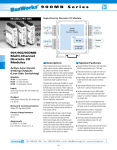
USB-Isolator
USER’S MANUAL
ACROMAG INCORPORATED
30765 South Wixom Road
P.O. BOX 437
Wixom, MI 48393-7037 U.S.A.
Tel: (248) 295-0880
Fax: (248) 624-9234
Email: [email protected]
Web: http://www.acromag.com
Copyright 2010 Acromag, Inc., Printed in the USA.
Data and specifications are subject to change without notice.
8500-900-B10M012
2
USB-Isolator User’s Manual
_________________________________________________________________________________
OVERVIEW
•
Fully Isolated power and I/O circuits for safety and increased noise
immunity.
Key Features
•
CE and FCC Compliant. Designed to meet and exceed EN61000
specifications.
•
High retention USB connectors provide minimum withdrawal force of
15 Newtons.
•
USB bus powered and no need for external power.
•
USB Cable Included, 1 meter USB cable (Type A to Type B).
•
USB 2.0 compatible.
•
Changeable Data Rate allows selectable full-speed 12Mbps (Default),
or low-speed 1.5Mbps.
•
Wide Ambient Operation from -40° to 70°C (-40° to +158°F).
•
Hardened For Harsh Environments and includes protection from RFI,
EMI, ESD, EFT, & surges. Has low radiated emissions per CE
requirements.
•
Power LED provides power indication and overload indication.
•
Reset Push Button is a useful feature for reinitializing peripherals
without unplugging cables.
•
Built in Current Limiting with Auto Retry prevents damage to isolator
and connected USB devices.
•
Small, compact and rugged housing design.
•
Easy to install with existing equipment.
•
No special drivers required.
_______________________________________________________________________________________
Acromag, Inc. Tel:248-295-0880 Fax:248-624-9234 Email:[email protected] http://www.acromag.com
USB-Isolator User’s Manual
_________________________________________________________________________________
3
HOW IT WORKS
This circuit isolates USB power and data via two transformers. Input power
is current limited to 200mA to help prevent damage to connected devices
(corresponding to ~137mA out load). Both signal lines are equipped with
common-mode filters and include transient protection. USB is set to full
speed (12 Mbps), but can be jumped to low speed (1.5 Mbps) for legacy
device support.
ISOLATED POWER
AND SIGNAL
CURRENT
LIMITER
GND
FROMPC
USB
B-TYPE
NOTE: FILTERING IS
SIMPLIFIED FOR THIS
DRAWING.
PUSH-PULL
DRIVER
+5V
+5V
POWER
LED
GND
DATA+
DATA+
TO TARGET
DEVICE
DATA-
DATA-
SHIELD
USB
A-TYPE
COMMON
MODE
FILTER
COMMON
MODE
FILTER
SHIELD
1500 VAC ISOLATION
PUSH
BUTTON
USB-ISOLATOR SIMPLIFIED SCHEMATIC
DIMENSIONS
_______________________________________________________________________________________
Acromag, Inc. Tel:248-295-0880 Fax:248-624-9234 Email:[email protected] http://www.acromag.com
4
USB-Isolator User’s Manual
_________________________________________________________________________________
Installation
1) Connect B-type plug (square connector) to ‘PC connect’ side of the USB
Isolator.
Guide to Quickly
Establishing
Communication
Note: This device is not
intended to isolate hubs.
Note: This isolator will break
the path to earth ground. Most
personal computers connect
the USB signal ground in
common with the cable shield
and earth ground. The PC
connector side of this isolator
also holds signal ground in
common with the connector
shield. The target device
connector side of this isolator
does not transfer the earth
ground connection across the
barrier that was made at the
PC side. If the device that you
are isolating must be earth
grounded, other provisions
must be implemented to
introduce earth ground to the
isolated side.
2) Connect A-type plug of USB cable to an available USB port on the
computer (the power LED will turn on when connected to a powered
computer).
3) Connect the A-type plug (flat connector) to the ‘device connect’ side of
the isolator. Connect the other side of the cable to the peripheral being
isolated. NOTE: This device is not intended to isolate the trunk of a
USB hub, as its output current is limited to ~137mA.
4) Your computer should prompt that a new device has been connected to
the computer. The power LED of the isolator should be ON and not
blinking. At this point, you are ready to begin talking to your connected
device.
TIP: If your PC fails to detect your USB device, try pushing the reset
connection button on the Isolator.
_______________________________________________________________________________________
Acromag, Inc. Tel:248-295-0880 Fax:248-624-9234 Email:[email protected] http://www.acromag.com
USB-Isolator User’s Manual
_________________________________________________________________________________
5
This is an optional procedure to change the data rate of the full-speed
USB-ISOLATOR to low speed.
Installation
In order to change the speed, it requires that the board be carefully removed
from the enclosure and this requires handling at an ESD-safe work station.
Changing USB Speed
!
Warning: We do not recommend that you do this in the
field, as it invites potential damage to sensitive internal
circuitry.
Note: Default speed is set to
full-speed (12Mbps)
1) Open enclosure by unscrewing Phillips head screw on bottom of the
case (a label sticker will have to be pulled up to access this screw).
2) To Switch to Low Speed (1.5Mbps): Remove jumpers J1 and J2 and
replace as shown below (right-most position).
Note: If both jumpers are not set the same way the unit will not function
properly
_______________________________________________________________________________________
Acromag, Inc. Tel:248-295-0880 Fax:248-624-9234 Email:[email protected] http://www.acromag.com
6
USB-Isolator User’s Manual
_________________________________________________________________________________
Installation
This is an optional procedure to change the data rate of the USBISOLATOR to high speed.
Changing USB Speed
1) To Switch to High Speed (12Mbps): Remove jumpers J1 and J2 and
replace as shown below (left most position).
Note: If both jumpers are not set the same the unit will not function properly
2) Carefully place board back into enclosure and mate both sides of
enclosure. Install the screw in the bottom of enclosure. The isolator is
now ready for operation.
Troubleshooting
POSSIBLE CAUSE
POSSIBLE FIX
The power LED does not light up when plugged into USB port…
No power on the USB port or USB
Try plugging the unit into another
port is bad.
USB port.
USB A-B cable is bad.
Replace cable.
Cannot communicate with device connected through the Isolator…
Your computer does not support
the peripheral .
Your device does not support
Try changing internal jumpers to low
12Mbps.
speed (see page 5).
You do not have the speed set
Verify internal jumpers are BOTH set
identically for each side.
to the same speed.
The LED is ON and the peripheral is powered but the computer will not
prompt me to indicate the device is connected…
Loose connection.
Check both cable connections, make
sure they are properly and securely
fitted into the USB connection ports
at both ends.
The PC could not recognize the
Press the ‘reset connection’ button on
device.
the USB isolator. If this does not
work, try replugging the cable.
I plug in my device but the power LED is blinking and the computer will not
prompt me that a device is connected...
Peripheral is drawing too much
The USB isolator will not provide
current for the isolator.
more than 120mA to peripheral,
Unplug peripheral and plug it directly
into PC (this is not isolated).
_______________________________________________________________________________________
Acromag, Inc. Tel:248-295-0880 Fax:248-624-9234 Email:[email protected] http://www.acromag.com
USB-Isolator User’s Manual
_________________________________________________________________________________
7
Case Material: Plastic non-conductive. UL-94 HB flammability rating.
Dimensions: 2.40” Length x 1.85” Wide x 0.925” High
(60.96mmx46.99mmx23.495mm)
Cable Length: Maximum cable length is 5 meters on each side.
SPECIFICATIONS
Connectors: High retention USB Type A (x 1) and USB Type B (x 1)
connectors with minimum withdrawal force of 15 Newton’s
Data Rate: Selectable full-speed 12Mbps (Default) or low-speed 1.5Mbps.
Transient Protection: Transient Voltage Suppressors are applied at both
the PC and target device ports. The metal cable shield is connected to
signal GND though a ferrite.
USB Interface
Power LED - Constant ON if power is on and unit is OK. Blinking ON/OFF
indicates unit is in current limit mode (>137mA) and the connected
device is drawing too much power.
Controls and Indicators
Safety Approvals (All Pending): CE marked (EMC Directive
2004/108/EC), UL Listed (UL508, ANSI/ISA 12.12.01, 2007), cUL Listed
(Canada Standard C22.2, Nos. 142-M1987 and 213-M1987)
Electromagnetic Compatibility (EMC) Immunity Per European Norm EN61000-6-2:2005:
Electrostatic Discharge (ESD) Immunity: 4KV direct contact and 8KV
air-discharge to the enclosure port per IEC61000-4-2.
Radiated Field Immunity (RFI): 10V/M, 80 to 1000MHz AM, 1.4 to
2GHz 3V/M, and 2 to 2.7GHz 1V/M, per IEC61000-4-3.
Electrical Fast Transient Immunity (EFT): 2KV to power, and 1KV to
signal I/O per IEC61000-4-4.
Conducted RF Immunity (CRFI): 10Vrms, 150KHz to 80MHz, per
IEC61000-4-6.
Surge Immunity: 0.5KV per IEC61000-4-5.
Emissions Per European Norm EN61000-6-4:2007
Radiated Frequency Emissions: 30 to 1000MHz per CISPR16 Class A
WARNING: This is a Class A product. In a domestic environment, this
product may cause radio interference in which the user may be
required to take adequate measures.
Agency Approvals
Power Supply: Standard 5VDC power provided from the USB host
computer up to 120mA of current.
Current Limit: Isolator is equipped with a 200mA input limiter to isolator
and this corresponds to ~137mA out. Once limit is reached, power will
open and retry momentarily, repeatedly until the current draw is less
than 200mA.
Isolation: USB power and data circuits are isolated from each other for
common-mode voltages up to 250VAC, or 354V DC off DC power
ground, on a continuous basis (will withstand 1500VAC dielectric
strength test for one minute without breakdown). Complies with test
requirements of ANSI/ISA-82.01-1988 for voltage rating specified.
Operating Temp: -40°C to +70°C (-40°F to +149°F).
Relative Humidity: 5 to 95%, non-condensing.
Environmental
Enclosure and Physical
_______________________________________________________________________________________
Acromag, Inc. Tel:248-295-0880 Fax:248-624-9234 Email:[email protected] http://www.acromag.com
8
USB-Isolator User’s Manual
_________________________________________________________________________________
Notes:
_______________________________________________________________________________________
Acromag, Inc. Tel:248-295-0880 Fax:248-624-9234 Email:[email protected] http://www.acromag.com