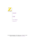
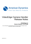
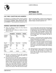
1
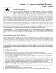
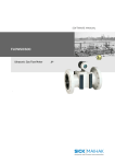
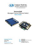
ComSync/PCI-104 User Manual
Mode
V.10
V.11
V.28
V.35
Table 11: Signal Description
Equivalent Standard
Electrical
RS-423
Single ended
RS-422 / RS485
Differential
RS-232
Single ended
V.35
Differential
Typical Voltage
+/- 5VDC
1.5VDC to 4.5VDC
+/-12VDC
550mVDC
Connecting Serial Devices
V.28 Connections
V.28 has signaling levels compatible with EIA RS-232. The Signal Reference (SR) pin must always be
connected. This pin provides the ground return path for all signaling.
Basic Asynchronous (V.28) RS-232
The figure below illustrates the typical way to connect the ComSync/PCI-104 to a serial device.
Figure 7: Basic V.28 Asynchronous Connections
Figure 8: Basic V.28 Synchronous Connections
RS-422/V.11 Connections
The following basic connections are achieved when the I/O levels are in V.11 (RS-422) mode.
V.11 mode signaling can be enabled with EIA-530, RS-449 or X.21 modes on your ComSync/PCI-104.
The Signal Reference (SR) pin should always be connected. This pin provides the ground return path for all
signaling.
Figure 9: Basic RS-422/V.11 Asynchronous Connections
19
www.connecttech.com
800-426-8979 | 519-836-1291
CTIM-00048 (0.00) 10/31/2008