1
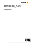
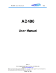
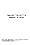
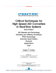
SMT390-VP
User Manual
Version 2.4
Page 2 of 55
SMT390-VP User Manual
Revision History
Date
Comments
Engineer
05/02/04
Preliminary version.
PSR
0.9
19/02/04
Trigger characteristics added – SHB Location
corrected.
PSR
1.0
18/03/04
Details about clock synthesizer configuration.
Dimensions added. MTBF Added
PSR
1.1
29/03/04
Details on
SMT338VP
to
PSR
1.2
01/04/04
Update temperature
registers
number
PSR
1.3
19/05/04
Update Configuration sequence and power
connector pinout (JTAG lines were missing)
PSR
1.4
25/05/04
Changed title to SMT390-VP
JPA
1.5
JPA
1.6
how
to
connect
and
SMT390
serial
Version
Update Register Description section:
-
Trigger Register
-
Decimation Register
-
ADC over range register
SHB and ComPort sections updated
15/06/04
Removed MemoryBypass Mode.
Updated registers section.
RSL are not available.
Updated ADC Setup Control Register.
Added Firmware description section.
Added Setting-up an acquisition section.
Added Configuring the FPGA section.
28/06/04
Review and minor changes added
PSR
1.7
14/07/04
ADC and External clock schematics added –
Module temperatures added – FPGA usage
added
PSR
1.8
24/03/05
Due
to
complete
recoding
of
the
microcontroller code the serial number feature
has been removed. Also correction of the
interface between the microcontroller and the
FPGA.
E.P
1.9
Version 2.4
07/06/05
Page 3 of 55
Added: power consumptions
SMT390-VP User Manual
SM
2.0
Corrected: SDRAM storage capacity 63.75MB
Corrected: Figure 30 – SHB control register
22/09/06
Information about cooling added
PSR
2.1
12/11/06
Input speficied in dBms
PSR
2.2
06/12/06
Clock synthesizer corrected
PSR
2.3
25/05/07
Reference oscillator details added
PSR
2.4
Version 2.4
Page 4 of 55
SMT390-VP User Manual
Table of Contents
Revision History............................................................................................................ 2
Table of Contents ......................................................................................................... 4
Table of Figures............................................................................................................ 6
Precautions (Please Read this!)................................................................................... 7
Physical Properties ....................................................................................................... 8
Dimensions ............................................................................................................... 8
Introduction ................................................................................................................. 10
Introduction ................................................................................................................. 10
Overview ................................................................................................................. 10
Module features ...................................................................................................... 10
Power consumption ................................................................................................ 10
Possible applications .............................................................................................. 11
Related Documents ................................................................................................ 11
Functional Description ................................................................................................ 11
Block Diagram......................................................................................................... 11
Module Description ................................................................................................. 12
Communication Ports (ComPorts). ......................................................................... 13
Sundance High-speed Bus - SHB. ......................................................................... 13
Inputs and outputs main characteristics ................................................................. 14
Data Stream Description......................................................................................... 16
Block diagram...................................................................................................... 16
Description of Internal FPGA Blocks................................................................... 17
Clock Structure........................................................................................................ 18
Power Supply and Reset Structure......................................................................... 19
MSP430 Functionality ............................................................................................. 20
Analog input section................................................................................................ 22
ADC Settings........................................................................................................... 22
Description of Interfaces............................................................................................. 22
Memory Interface .................................................................................................... 22
MSP430 Interface ................................................................................................... 22
Serial Number ......................................................................................................... 22
Version 2.4
Page 5 of 55
SMT390-VP User Manual
Green LEDs ............................................................................................................ 23
ADC Data Interface................................................................................................. 23
Clock synthesizer Interface..................................................................................... 23
Clock Routing.......................................................................................................... 23
TIM Interface ........................................................................................................... 23
RSL Interface (RSL are not available) .................................................................... 23
RSL Connector and Pinout Definition ................................................................. 23
RSL Cable Definition ........................................................................................... 27
SHB ......................................................................................................................... 27
Daughter-card Interface .......................................................................................... 30
Firmware description .................................................................................................. 37
SHB full word configuration..................................................................................... 38
SHB half word configuration ................................................................................... 38
Setting-up an acquisition ............................................................................................ 38
Configuring the FPGA ................................................................................................ 39
Control Register Settings............................................................................................ 40
Control Packet Structure......................................................................................... 40
Reading and Writing Registers ............................................................................... 40
Memory Map ........................................................................................................... 41
Register Descriptions.............................................................................................. 42
Global FPGA Reset Register (0x00) ................................................................... 42
Clock Synthesizer Control Register (0x02) ......................................................... 42
Clock Routing Selection Register (0x03) ............................................................ 42
Acquisition trigger register (0x06) ....................................................................... 43
ADC Setup Control Register (0x07) .................................................................... 44
Decimation Register (0x08)................................................................................. 44
SHB Control Register (0x09)............................................................................... 44
Main Module Temperature Register (0x0A)........................................................ 45
Main Module FPGA Temperature Register (0x0B) not available........................ 45
Daughter Module Temperature Register (0x0C) not available ........................... 45
Daughter Module ADC Temperature Register (0x0D) not available .................. 45
Main Module Silicon Serial Number Words0, 1, 2 and 4 (0x10, 11, 12 and 13). 45
Daughter Module Silicon Serial Number Words0, 1, 2 and 4 (0x14, 15, 16 and
17). not available ................................................................................................. 45
Version 2.4
Page 6 of 55
SMT390-VP User Manual
Firmware Version Registers (0x1A) .................................................................... 45
PCB Layout................................................................................................................. 46
Connector Location .................................................................................................... 49
JTAG Cable pinouts ................................................................................................... 50
Virtex II PRO FPGA. ............................................................................................... 50
TI MSP430 Microcontroller ..................................................................................... 51
How to interconnect SMT390 and SMT338-VP on a carrier board?.......................... 52
Appendix..................................................................................................................... 55
Table of Figures.
Figure 1 - Side View Module. ....................................................................................... 9
Figure 2 - General block diagram............................................................................... 12
Figure 3 - Main features. ............................................................................................ 14
Figure 4 - ADC input stage. ........................................................................................ 15
Figure 5 - External Clock Input Stage. ....................................................................... 15
Figure 6 – Internal FPGA Architecture. ...................................................................... 16
Figure 7 - Clock Structure........................................................................................... 18
Figure 8 – Power Generation and Distribution ........................................................... 20
Figure 9 - Microcontroller State Machine. .................................................................. 21
Figure 10 – Rocket Serial Link Interface. ................................................................... 24
Figure 11 – Rocket Serial Link Interface Connector and Pinout (RSL A) .................. 25
Figure 12 – Rocket Serial Link Interface Connector and Pinout (RSL B) .................. 26
Figure 13 – Samtec HFEM Series Data Cable. ......................................................... 27
Figure 14 –SHB Connector Configuration 2 Pinout. .................................................. 29
Figure 15 – Daughter Card Connector Interface........................................................ 30
Figure 16 – Daughter Card Interface Power Connector and Pinout .......................... 32
Figure 17 – Daughter Card Interface: Data Signals and Pinout (Bank A). ............... 33
Figure 18 – Daughter Card Interface: Data Signals and Pinout (Bank B). ................ 35
Figure 19 – Daughter Card Interface: Data Signals and Pinout (Bank C). ................ 36
Figure 20: SMT390-VP state diagram........................................................................ 37
Figure 21: SMT390-VP channels output .................................................................... 38
Figure 22 – Setup Packet Structure. .......................................................................... 40
Version 2.4
Page 7 of 55
SMT390-VP User Manual
Figure 23 – Control Register Read Sequence. .......................................................... 40
Figure 24 – Register Memory Map............................................................................. 41
Figure 25 – Clock Synthesizer Control Register (0x02). ............................................ 42
Figure 26 – Clock Routing Register (0x03). ............................................................... 42
Figure 27 - Acquisition trigger register (0x06). ........................................................... 43
Figure 28 – ADC Setup Control Register (0x07)........................................................ 44
Figure 29 – Decimation Register (0x08)..................................................................... 44
Figure 30 – SHB control Register (0x08). .................................................................. 45
Figure 31 – Module Top View (Main Module). ........................................................... 46
Figure 32 – Module Bottom View (Main Module). ...................................................... 47
Figure 33 – Top View (Daughter-card)....................................................................... 47
Figure 34 - Bottom View (Daughter-card). ................................................................. 48
Figure 35 - Connector Location.................................................................................. 49
Figure 36 - Pinout FPGA JTAG cable. ....................................................................... 50
Figure 37 - Pinout MSP430 JTAG cable. ................................................................... 51
Figure 38 - SMT390 to SMT338-VP Interconnections. .............................................. 52
Figure 39 – Fixings ..................................................................................................... 52
Precautions (Please Read this!).
In order to guarantee that the SMT390-VP functions correctly and to protect the
module from damage, the following precautions should be taken:
- The SMT390-VP is a static sensitive product and should be handled accordingly.
Always place the module in a static protective bag during storage and transition.
- At all time, make sure that the heat generated by the system is extracted e.g. by
the use of a fan extractor or an air blower. Sundance recommends to use a fan (as a
reference : PAPST 8300 series - 12-Volts – 31.8 CFM) to blow across the PCI bus
when the board is used within a PCI system. This is vital not to damage any of
components.
- SHB and RSL connectors are similar but their use is really different. Do NOT
connect an SHB and an RSL connectors together with and SHB cable! This would
cause irreversible damages to the modules.
Version 2.4
Page 8 of 55
SMT390-VP User Manual
Physical Properties
Width: 63.5mm.
Dimensions
Length: 106.68mm.
Height: 21mm maximum.
Weight
104 Grams (including fan and fixings)
Supply Voltages
3.3V and 5V
Supply Voltages available on Daughter 1.5V, 2.5V, 3.3V, 5V, +12V and –12V
Module
+12V
Supply Current
+5V
+3.3V
-5V
-12V
31398.75 hours
MTBF
Temperatures (measured in a 23degree environment)
FPGA – SMT338-VP 67°C max
ADCs – back SMT390 52°C max
SMT390 board 45°C max
SMT338-VP board 61°C max
FPGA Usage
RAMB16 8 out of 136 (5%)
Slices 3909 out of 13696 (28%)
Bufgmux 9 out of 16 (56%)
DCMs 4 out of 8 (50%)
Version 2.4
Page 9 of 55
SMT390-VP User Manual
SMT390-VP
RF Daughtercard PCB
Inter PCB Connector
Only required for
debugging
Fan
7.6mm
ADC - 1.6MM
JTAG
6.4
mm
21.0 mm
SHB
1.2 mm
RSL
FPGA
T
Power
Stand-off
Module PCB
Figure 1 - Side View Module.
TIM Connectors
T
Version 2.4
Page 10 of 55
SMT390-VP User Manual
Introduction
Overview
The SMT390-VP is a single width TIM, which converts 2 analogue signals into two
12-bit resolution digital data flows. Analogue to digital conversion is performed by two
Analog Devices AD9430s - they are 3.3-Volt 12-bit data CMOS devices that can
sample at up to 210 MSPS.
Digital data travel to a Xilinx Virtex-II Pro FPGA (XC2VP30-6 - FF896 package),
controlled via ComPorts words. Samples are first stored into the on-board memory
and then transferred onto the Sundance High-speed Bus (SHB), common to a wide
range of Sundance products.
A copy of the data will also be streamed over the RocketIO Serial Links on the
module (RSL) in a future version. These interfaces are compatible with a wide range
of Sundance processor and I/O modules.
The FPGA is configured at power-up via Comport 3. The configuration process is
controlled by a microprocessor MSP430. Once the FPGA is configured, the
configuration ComPort becomes a control ComPort to set FPGA internal registers.
Module features
The main features of the SMT390-VP are listed below:
● Dual-ADC board,
● On-board low-jitter clock generation,
● 210 Mega Samples Per Second and per channel,
● 12-bit resolution,
● Two external clocks and two external triggers via MMCX (or MMBX – to be
specified on order) connectors,
● Two 64-MByte banks of DDR SDRAM for sample storage. Banks are
organised in 32-bit words.
● Two Standard Sundance ComPorts,
● Two SHB interfaces for easy interconnection to Sundance products,
● Two RSL (Rocket-IO Serial Link) interfaces for fast output transfers,
● All inputs are 50-Ohm terminated,
● On-board MSP430 microprocessor.
Power consumption
The SMT390-VP (SMT338-VP+SMT390) consumes about 9.57Watts (with data
acquisition running), and about 7.86Watts in idle state but after configuration of the
338VP).
Version 2.4
Page 11 of 55
SMT390-VP User Manual
Possible applications
The SMT390-VP can be used for the following application (this non-exhaustive list
should be taken as an example):
● Broadband cable modem head-end systems,
● 3G radio transceivers,
● High-data-rate point-to-point radios,
● Medical imaging systems,
● Spectrum analyzers
Related Documents
AD9430 Datasheet - Analog Devices
Sundance High-speed Bus (SHB) specifications – Sundance
Sundance LVDS Bus (SLB) Specifications – Sundance
TIM specifications
Xilinx Virtex-II PRO FPGA
MMCX Connectors – Hubert Suhner:
MMCX Connectors
Surface Mount MMCX connector
MMBX Connectors – Hubert Suhner:
MMBX Connectors
Surface Mount MMBX connector
Sundance’s firmware general description - SMT6400
Functional Description
In this part, we will see the general block diagram and some comments on each of its
entities.
Block Diagram
The following picture shows the block diagram of the SMT390-VP.
LVPECL
Trigger
Distribution
2 Ext
Trigger
Inputs
(MMCX)
Notes:
Channel B
Signal
Conditioning
Channel B
Input
MMCX
Connector
Vin B
(1d)
Vin A
(1d)
Debug IOs
and LEDs
ADC - AD9430
12-bit 210MSPS
ADC - AD9430
12-bit 210MSPS
Clock (2d)
The numbers in brackets denote
the amount of FPGA IO pins
requires. 'd' is used for differential
pairs. 1d Will thus requre 2 IOs
Power
Channel A
Signal
Conditioning
LVPECL
Clock
Generation and
Distribution
Channel A
Input
MMCX
Connector
2 Ext.
Clock
Inputs
(MMCX)
Low Jitter
Local Oscillator
Data (21)
Control (4)
Trigger (2d)
512MBit for
Channel B
ChB Data, Clock
and Control (14d)
ChA Data, Clock
and Control (14d)
Clock (1d)
Control (4)
Control (6)
512MBit for
Channel A
256MBit
DDR SDRAM
256MBit
DDR SDRAM
Data, Clock and
Control (93)
256MBit
DDR SDRAM
508 / 556 IOs
FF896 Package
Virtex-II Pro
XC2VP20-6 or 30-6
Data, Clock and
Control (93)
256MBit
DDR SDRAM
ChB Data, Clock
and Control (60)
DataTx (4d)
DataRx (4d)
ComPorts and
Control (59)
DataTx (4d)
DataRx (4d)
ChA Data, Clock
and Control (60)
SHB for Channel B
4 RocketIO
Links for Channel A
(1GByte/s effective
Data throughput)
Top and Bottom TIM
Connectors
4 RocketIO
Links for Channel A
(1GByte/s effective
Data throughput)
SHB for Channel A
Version 2.4
Page 12 of 55
SMT390-VP User Manual
Figure 2 - General block diagram.
Module Description
The module is built around a Xilinx Virtex-II Pro FPGA and two Analog Devices
AD9430 12-bit monolithic analog-to-digital converters.
Version 2.4
Page 13 of 55
SMT390-VP User Manual
Analog data enters the module via two MMCX connectors, one for each channel.
Both signals are then conditioned (AC coupling) before being digitized. Both ADCs
gets their own sampling clock, which can be either on-board generated or from an
external source (MMCX connector). ADCs can receive either their own external clock
or both the same external clock or both the same on-board clock, or even opposite
external clocks. Two more MMCX connectors are dedicated for two external trigger
signals. External clocks and triggers can be either single-ended or differential (the
selection is made on hardware), whereas the analogue input is single-ended only.
ADCs digital outputs are fed into the FPGA. They can be passed directly on both
SHB connectors or stored into the on-board DDR SDRAM memory to be transferred
afterwards via SHB connectors. ADCs data stream can also be transmitted via RSL
connectors (RSL will be available on a future version of the FPGA firmware).
The design of the SMT390-VP is split over two PCBs. The main PCB (main module –
SMT338-VP) contains the FPGA, the memory, the microcontroller and the digital
connector interfaces (TIM, SHB and RSL). The second PCB (daughter card –
SMT390) contains all the analogue circuitry as well as the clock generation, trigger
control, analogue signal conditioning and ADCs.
The FPGA gets control words from a ComPort interface following the Texas
Instrument C4x standard. It then feeds both ADCs with a differential encode signal,
from one of the following sources: external (via MMCX connector) or internal (onboard clock generator). Two parallel LVDS buses carry 12-bit samples (2’s
complement or offset binary format - SLB) from both converters to the FPGA, which
sends them out through both SHB connectors. Note that samples coming from ADC
Channel A are output on SHBB (J8) and that samples coming from ADC Channel B
are output on SHBA (J7).
Two full (60-pin) SHB connectors are accessible from the FPGA. They are output
only to send out digital samples to another module. Please refer to the SHB
specifications for more details about ways connectors can be configured.
A global reset signal is mapped to the FPGA from the bottom TIM connector via the
MSP430 microcontroller.
Communication Ports (ComPorts).
The SMT390-VP provides 2 ComPorts: 0 and 3.
ComPort 3 is used to configure and send control words the FPGA.
The SMT6400 help file provides more information about ComPorts.
The ComPorts drive at 3.3v signal levels.
Sundance High-speed Bus - SHB.
2 SHB connectors are used to transmit data coming from ADCs to external world.
Both SHB buses are identical and 60-bit wide.
See SHB technical specification for more information.
Version 2.4
Page 14 of 55
SMT390-VP User Manual
Inputs and outputs main characteristics
The main characteristics of the SMT390 are gathered into the following table.
Analogue inputs
11dBms – Full scale (twice for Half Scale)
AC coupled.
Input voltage range
(Scale selection via control register)
Impedance
50Ω - terminated to ground – single ended
ADC bandwidth: 700 MHz.
Bandwidth
Input RF transformer: 800MHz.
External sampling clock inputs
Single ended or differential (3.3V PECL) –
AC coupled.
Format
40-210 MHz
Frequency range
External Trigger inputs
Single ended or differential (3.3 V PECL) –
DC coupled.
Format
1.4 Volts peak-to-peak minimum
Input Voltage range
105 MHz maximum
Frequency range
SMT390 Output
Output Data Width
12-Bits
2’s Compliment or offset binary
Data Format
(Changeable via control register)
SFDR
Up to 68dB (80dB is the maximum
provided by Analogue Devices)
SNR
Up to 56dB (65dB is the maximum
provided by Analogue Devices)
Maximum Sampling Frequency
210 MHz.
SMT390 On-board reference crystal
(used by clock synthesizer)
16MHz
Frequency
Frequency stability over
temperature
Part number
+/-50ppm typical
Raltron AS-SMD series
(AS-16.000-18-SMD)
Figure 3 - Main features.
Version 2.4
Page 15 of 55
SMT390-VP User Manual
The following pieces of schematic show the Analogue and External clock input
stages:
Figure 4 - ADC input stage.
Figure 5 - External Clock Input Stage.
Version 2.4
Page 16 of 55
SMT390-VP User Manual
Data Stream Description
Block diagram
The data-path for both channels (ADCs) on the module and in the FPGA is identical.
The ADCs are driven by its own clock either generated on the module or provided by
the user through an MMCX connector. The following diagram shows the data-path
inside the FPGA.
DDR SDRAM
Memory Interface
Pre-process
Data
ADC A
Channel A
ADC B
Channel B
Store in
Memory
Retrieve from
Memory
SHB Interface
SHB for Channel B
Pre-process
Data
SI
RSL for Channel A
Pre-process
Data
SI
RSL for Channel B
SHB Interface
SHB for Channel A
Duplicate
Data
Duplicate
Data
Pre-process
Data
Store in
Memory
Retrieve from
Memory
Memory Interface
DDR SDRAM
Figure 6 – Internal FPGA Architecture.
The analog data are converted by the ADC converters. A single 12-bit parallel LVDS
data-stream is generated by each ADC (i.e. for each channel). This data-stream is
duplicated in the FPGA. One stream is transmitted as is over the RSL interface for
real-time type applications (RSL will be available on a future version of the FPGA
firmware). The second data-stream is stored in DDR SDRAM every time a trigger is
received. This data is kept in the memory until a non-real-time type module collects
the data over the SHB interface. Note that samples coming from ADC Channel A are
output on SHBB (J8) and that samples coming from ADC Channel B are output on
SHBA (J7).
Version 2.4
Page 17 of 55
SMT390-VP User Manual
Description of Internal FPGA Blocks
Duplicate Data
This block takes the incoming data stream and makes two copies of it. The first copy
is used for real-time type applications where the full conversion data-stream is
transmitted off the module. This option is not available yet. The second stream is for
non-real-time type applications where samples are captured and stored in memory.
Pre-processing Data
The data pre-processing block performs basic operations on the data-stream
(Decimation).
SI
The Serial Interface block takes the parallel input data stream and converts it into a
high-speed serial data stream. This data stream is 16b encoded. On the receiving
side the clock is recovered out of the serial data stream and the 16b data is decoded
to 12b.
Store in Memory
The store in memory block takes the incoming data stream and stores the data into
DDR SDRAM. This block will only transfer data into the memory when a valid trigger
command is received. The amount of data that must be stored is configurable.
Memory Interface
The memory interface block is the DDR SDRAM controller. This block is responsible
to all write and read transactions to and from the DDR SDRAM. Each 12-bit sample
is stored into a 16-bit memory location or two samples packed into a 32-bit word.
Retrieve from Memory
The retrieve from memory block retrieves stored data in the DDR SDRAM when it
receives a valid read command. The read command specifies the location and
amount of data that needs to be retrieved.
Version 2.4
Page 18 of 55
SMT390-VP User Manual
SHB Interface
The retrieved data from the ‘Retrieve from Memory’ block is transmitted over the SHB
interface. The SHB interface controls the SHB bus between the SMT390-VP and any
module connected to the SHB requesting the data.
Clock Structure
There is an integrated clock generator on the module. The user can either use this
clock or provide the module with an external clock (input via MMCX connector). The
RSL interface will only function if the module’s integrated clock is used (RSL are not
available).
External Clocks
Module Clock
External Clock Inputs
(MMCX)
Clock synthsizer
LVPECL
Buffers
TTL to LVPECL
4:2 Mux with Dual Output
ADCB
Ch B Clock
Ch A Clock
ADCA
LVDS
SerDes
Clock
RSL
Clock
DLL
Sys
Clock
DLL
FPGA
Diagram Key:
210 MHz LVPECL Clock
Figure 7 - Clock Structure.
Clock
Control
Version 2.4
Page 19 of 55
SMT390-VP User Manual
Each ADC can receive as encode signals, the on-board clock or its own external
clock or the other channel’s clock. It also means that an external clock can encode
both ADCs.
Power Supply and Reset Structure
The SMT390-VP conforms to the TIM standard for single width modules. The TIM
connectors supply the module with 5.0V. The module also requires an additional
3.3V power supply, which must be provided by the two diagonally opposite mounting
holes. This 3.3V is present on all Sundance TIM carrier boards. From the 5.0V the
FPGA Core Voltage (VCCINT = 1.5V), the FPGA Auxiliary voltage (VCCAUX = 2.5V) is
generated. The FPGA IO Voltage (VCCO = 3.3V) is taken straight from the TIM
mounting holes. The 3.3V, 5.0V, +12V and –12V present on the TIM connector are
passed up to the daughter card, as well as a 1.5V and a 2.5V. The daughter card is
responsible for generating its required voltages.
A TI MSP430 low power microprocessor is located on the main module. This
microprocessor controls the power sequencing for the main module. High efficiency
Vishay DC/DC converters are used to generated the lower voltages.
On the daughter card the Analog Devices ADCs require analog and digital 3.3V. The
3.3V from the main module to daughter card power connector is used for the digital
3.3V. This voltage is taken from the 5-Volt rail and filtered to provide the analog 3.3V.
The MSP430 microprocessor also controls the reset sequence for the SMT390-VP.
There are two possible reset sources for the SMT390-VP:
1. A reset is received over the TIM connector
2. After power up an internal Power On Reset in the MSP430 causes a reset
Version 2.4
Page 20 of 55
SMT390-VP User Manual
The MSP430 distributes the reset to the daughter board. The following diagram
illustrates the power distribution and the reset distribution on the SMT390-VP:
TIM Connector
D+5V0_IN
TIM
Mounting Hole
D+3V3_IN
Vccaux
DC / DC
Converter
D+2V5
Vccint
DC / DC
Converter
D+1V5
Analog Power
Switch
On / Off
Control
Voltage
Measure
D+3V3
Daughter Card
Main Module to
Daughter Card
Power
Connector
Voltage
Measure
MSP430
Microprocessor
D+3V3
Analog Filter
Vadcio
DC / DC
Converter
A+3V3
D+2V25
Main Module
Figure 8 – Power Generation and Distribution
MSP430 Functionality
The MSP430 implements analog control functionality that is difficult to implement in
the FPGA. The microprocessor
•
Controls the power start-up sequence
•
Controls the reset structure on the module
The following diagram shows what the default microcontroller boot code does:
Version 2.4
Page 21 of 55
SMT390-VP User Manual
TIM Reset
or nConfig
INIT
Start Key Received
FPGA Configured and
End Key Received
CONFIG
FPGA Configured
and End Key Received
IDLE
Figure 9 - Microcontroller State Machine.
At power-up or on a TIM Reset or on a nConfig line going low, the state machine
goes into an INIT State. TIM Reset and nConfig lines are available on the carrier
module – see TIM Specifications for location on TIM connectors).
From there, it has two choices depending on the state of the FPGA (configured i.e.
DONE pin high or un-programmed i.e. DONE Pin Low). To reconfigure the FPGA,
simply send a Start Key followed by the bitstream and then and End Key. To re-start
the FPGA with the current bitstream loaded, simply send an End Key.
Start Key = 0xBCBCBCBC and End Key = 0xBCBCBC00.
A TIM Reset can be issued to reconfigure the FPGA at anytime, but may reset other
modules as well. In the case of reconfiguring a particular module, the nConfig line is
used.
MSP430 is connected to ComPort 3 of the TIM. ComPort 0 is used to communicate
with FPGA.
Version 2.4
Page 22 of 55
SMT390-VP User Manual
Analog input section
Both analog inputs are AC-coupled (RF transformers).
ADC Settings
A sub-set of all the features of the AD9430 is implemented on the SMT390-VP: S1
for the data format (two’s complement or binary) and S5 for the scale (half or full).
Description of Interfaces
Memory Interface
Two groups of two 16-bit Samsung DDR SDRAMs form the volatile sample storage
space of the module. Each DDR SDRAM is 256 MBits in size. This provides the
module with a total of 64MBytes (or 32 Mega samples) of storage space per channel
- each 12-bit sample is stored into at 16-bit data location. Memory is implemented as
a block of 32-bit width.
Each channel contains a 32-bit DDRSDRAM controller. This interface is capable of
data transfer at 840MBytes/s. It is thus fast enough to write the incoming ADC data
stream into memory.
Note that only 63.75 MB are actually used to store the samples from the ADC.
MSP430 Interface
An 8-bit interface is implemented between the FPGA and the microprocessor. The
FPGA is the master and the microprocessor is the slave. This interface is used by the
microprocessor to write four temperature readings into a set of registers implemented
in the FPGA to make them available to the User.
Serial Number
This feature is removed from the SMT390-VP in later versions shipped after
25/05/2005.
Data can still be read out of the FPGA, but will have no meaning as the
microcontroller does not make any reading of serial number anymore.
A serial number is available on a sticker placed on the SMT390-VP.
Version 2.4
Page 23 of 55
SMT390-VP User Manual
Green LEDs
There is a total of 7 LEDs on the Daughter Module. Three are dedicated for the
power supplies (3.3Volt, 3.3V ADC Channel A and ADC Channel B). Four are driven
by the FPGA - they are noted on the PCB 1, 2, 3 and 4. LED1 reflects the state of
External Trigger A (J7) and LED2 the state of the External Trigger Channel B (J10).
LEDs 3 and 4 are for internal debug purpose.
ADC Data Interface
The output of each ADC is a 12-bit LVDS data bus with an LVDS clock. This clock
and data bus is connected straight to high-speed LVDS transceivers on the Xilinx
Virtex II Pro FPGA.
Clock synthesizer Interface
A three wire unidirectional control interface is implemented between the FPGA and
the on-board clock synthesizer (SY89429 - Micrel). The clock synthesizer is
configurated via two variables M and N.
Fsynthesizer = 2xM / N’
Where 200 < M < 475
And N’ = 2 when N=0, 4 when N=1, 8 when N=2 and 16 when N=3.
For example: to have an on-board clock of 210 MHz, set M to 420 (decimal) and N to
4 (decimal).
Clock Routing
The clock routing for both ADC channels is symmetrical. A difference of less than
100ps has been measured.
TIM Interface
The SMT390-VP implements ComPorts 0 and 3. There are no DIP switches on the
module and all configuration data is received and transmitted over these two ports.
None of the ComPorts is used for ADC data transfer. ComPort 3 is implemented as a
bi-directional interface for FPGA configuration and control operations. ComPort 0 is
available but not used in the default Firmware provided with the board.
RSL Interface (RSL are not available)
RSL Connector and Pinout Definition
The Rocket Serial Link (RSL) is a serial based communications interconnection
standard that is capable of transfer speeds of up to 2.5GBit/s per link. Up to four links
can be combined to form a Rocket Serial Link Communications Channel (RSLCC)
that is capable of data transfer up to 10GBit/s.
Each RSL is made up of a differential Tx and Rx pair. A single RSL can thus transfer
data at 2.5GBit/s in both directions at the same time. Rocket Serial Link
Version 2.4
Page 24 of 55
SMT390-VP User Manual
interconnections are based on the RocketIO standard used on Xilinx Virtex-II Pro
FPGAs. Rocket Serial Links uses Low Voltage Differential Signalling (LVDS).
The SMT390-VP uses a subset of the RSL specification. Two RSLs are combined to
form a 5GBit/s RSLCC. One RSLCC per ADC channel is implemented on the
SMT390-VP. The RSLCC is thus capable to transfer the raw data stream of the ADC
in real time.
SHB
A
SHB
B
FPGA
Config
Samsung
DDR266 SDRAM
Samsung
DDR266 SDRAM
Power
Figure 10 – Rocket Serial Link Interface.
Bottom Primary TIM Connector
RSL
A
Daughter Card Expansion Connector
Top Primary TIM Connector
Daughter Card
Power Conn
RSL
B
The connector used for the RSL interface is a 0.8mm pitch differential Samtec
connector. The part number for this connector is: QSE-014-01-F-D-DP-A. The RSL
connector takes the place of the optional 3rd and 4th SHB connector on a TIM module.
The following diagram shows the position of the RSL connectors on the SMT390-VP:
Version 2.4
24
Page 25 of 55
SMT390-VP User Manual
68
13
57
RSL A
Pin No
Pin Name
Signal Description
Pin No
Pin Name
Signal Description
Dir
Carrier / Other Module to SMT390-VP
Dir
SMT390-VP to Carrier / Other Module
1
RxLink0p
Receive Link 0, positive
2
TxLink0p
Transmit Link 0, positive
3
RxLink0n
Receive Link 0, negative
4
TxLink0n
Transmit Link 0, negative
Dir
Carrier / Other Module to SMT390-VP
Dir
SMT390-VP to Carrier / Other Module
5
RxLink1p
Receive Link 1, positive
6
TxLink1p
Transmit Link 1, positive
7
RxLink1n
Receive Link 1, negative
8
TxLink1n
Transmit Link 1, negative
Dir
Reserved
Dir
Reserved
9
Reserved
Reserved
10
Reserved
Reserved
11
Reserved
Reserved
12
Reserved
Reserved
Dir
Reserved
Dir
Reserved
13
Reserved
Reserved
14
Reserved
Reserved
15
Reserved
Reserved
16
Reserved
Reserved
Dir
Reserved
Dir
Reserved
17
Reserved
Reserved
18
Reserved
Reserved
19
Reserved
Reserved
20
Reserved
Reserved
Dir
Reserved
Dir
Reserved
21
Reserved
Reserved
22
Reserved
Reserved
23
Reserved
Reserved
24
Reserved
Reserved
Dir
Reserved
Dir
Reserved
25
Reserved
Reserved
26
Reserved
Reserved
27
Reserved
Reserved
28
Reserved
Reserved
Figure 11 – Rocket Serial Link Interface Connector and Pinout (RSL A)
Version 2.4
Page 26 of 55
SMT390-VP User Manual
RSL B
Pin No
Pin Name
Signal Description
Pin No
Pin Name
Signal Description
Dir
Carrier / Other Module to SMT390-VP
Dir
SMT390-VP to Carrier / Other Module
1
RxLink0p
Receive Link 0, positive
2
TxLink0p
Transmit Link 0, positive
3
RxLink0n
Receive Link 0, negative
4
TxLink0n
Transmit Link 0, negative
Dir
Carrier / Other Module to SMT390-VP
Dir
SMT390-VP to Carrier / Other Module
5
RxLink1p
Receive Link 1, positive
6
TxLink1p
Transmit Link 1, positive
7
RxLink1n
Receive Link 1, negative
8
TxLink1n
Transmit Link 1, negative
Dir
Reserved
Dir
Reserved
9
Reserved
Reserved
10
Reserved
Reserved
11
Reserved
Reserved
12
Reserved
Reserved
Dir
Reserved
Dir
Reserved
13
Reserved
Reserved
14
Reserved
Reserved
15
Reserved
Reserved
16
Reserved
Reserved
Dir
Reserved
Dir
Reserved
17
Reserved
Reserved
18
Reserved
Reserved
19
Reserved
Reserved
20
Reserved
Reserved
Dir
Reserved
Dir
Reserved
21
Reserved
Reserved
22
Reserved
Reserved
23
Reserved
Reserved
24
Reserved
Reserved
Dir
Reserved
Dir
Reserved
25
Reserved
Reserved
26
Reserved
Reserved
27
Reserved
Reserved
28
Reserved
Reserved
Figure 12 – Rocket Serial Link Interface Connector and Pinout (RSL B)
Version 2.4
Page 27 of 55
SMT390-VP User Manual
RSL Cable Definition
The matching cable for the RSL connector is a Samtec High Speed Data Link Cable
(Samtec HFEM Series). The cable may be ordered with different length and mating
connector options. The following diagram shows such a typical cable:
Figure 13 – Samtec HFEM Series Data Cable.
SHB
The SMT390-VP implements a subset of the full SHB implementation. Two
configurations are possible
1. SHB A is configured to transmit 16-bit data words by the way of two
independent interfaces. The first half of the connector is dedicated to Channel
A and the second half to Channel B. Both interfaces are clocked at 53MHz.
This configuration isn’t available at the moment.
2. SHB A and SHB B are both configured to transmit 32-bits data words. Note
that SHB A is dedicated to ADC Channel B and SHB B to ADC channel A.
SHB interface is clocked at 53MHz.
Version 2.4
Page 28 of 55
SMT390-VP User Manual
The first configuration can be used if (a) just one SHB is available on a module that
the SMT390-VP interfaces to, or (b) when the data stream must be passed on two
different end points.
The second configuration is ideal for higher speed data transfer.
The connector used for the SHB interface is a 0.5mm Samtec QSH Type connector.
The full part number for this connector is: QSH-030-01-L-D-A-K.
246
135
SHB A and SHB B
Pin No
Pin Name
Direction
Signal Description
Pin Name
Direction
Signal Description
1
ChAClk
From 390
Ch A, ½Word Clock
Pin No
31
Reserved
Reserved
Reserved
2
ChAD0
From 390
Ch A, ½Word Data 0
32
Reserved
Reserved
Reserved
3
ChAD1
From 390
Ch A, ½Word Data 1
33
Reserved
Reserved
Reserved
4
ChAD2
From 390
Ch A, ½Word Data 2
34
Reserved
Reserved
Reserved
5
ChAD3
From 390
Ch A, ½Word Data 3
35
Reserved
Reserved
Reserved
6
ChAD4
From 390
Ch A, ½Word Data 4
36
Reserved
Reserved
Reserved
7
ChAD5
From 390
Ch A, ½Word Data 5
37
ChBClk
From 390
Ch B, ½Word Clock
8
ChAD6
From 390
Ch A, ½Word Data 6
38
ChBD0
From 390
Ch B, ½Word Data 0
9
ChAD7
From 390
Ch A, ½Word Data 7
39
ChBD1
From 390
Ch B, ½Word Data 1
10
ChAD8
From 390
Ch A, ½Word Data 8
40
ChBD2
From 390
Ch B, ½Word Data 2
11
ChAD9
From 390
Ch A, ½Word Data 9
41
ChBD3
From 390
Ch B, ½Word Data 3
12
ChAD10
From 390
Ch A, ½Word Data 10
42
ChBD4
From 390
Ch B, ½Word Data 4
13
ChAD11
From 390
Ch A, ½Word Data 11
43
ChBD5
From 390
Ch B, ½Word Data 5
14
ChAD12
Reserved
Not Implemented
44
ChBD6
From 390
Ch B, ½Word Data 6
15
ChAD13
Reserved
Not Implemented
45
ChBD7
From 390
Ch B, ½Word Data 7
16
ChAD14
Reserved
Not Implemented
46
ChBD8
From 390
Ch B, ½Word Data 8
17
ChAD15
Reserved
Not Implemented
47
ChBD9
From 390
Ch B, ½Word Data 9
18
ChAUser0
Reserved
Not Implemented
48
ChBD10
From 390
Ch B, ½Word Data 10
19
ChAUser1
Reserved
Not Implemented
49
ChBD11
From 390
Ch B, ½Word Data 11
20
ChAUser2
Reserved
Not Implemented
50
ChBD12
Reserved
Not Implemented
21
ChAUser3
Reserved
Not Implemented
51
ChBD13
Reserved
Not Implemented
22
ChAWen
From 390
Ch A, Write Enable
52
ChBD14
Reserved
Not Implemented
23
ChAReq
Reserved
Not Implemented
53
ChBD15
Reserved
Not Implemented
Version 2.4
Page 29 of 55
SMT390-VP User Manual
24
ChAAck
Reserved
Not Implemented
54
ChBUser0
Reserved
Not Implemented
25
Reserved
Reserved
Reserved
55
ChBUser1
Reserved
Not Implemented
26
Reserved
Reserved
Reserved
56
ChBUser2
Reserved
Not Implemented
27
Reserved
Reserved
Reserved
57
ChBUser3
Reserved
Not Implemented
28
Reserved
Reserved
Reserved
58
ChBWen
From 390
Ch B, Write Enable
29
Reserved
Reserved
Reserved
59
ChBReq
Reserved
Not Implemented
30
Reserved
Reserved
Reserved
60
ChBAck
Reserved
Not Implemented
Figure 14 –SHB Connector Configuration 2 Pinout.
Version 2.4
Page 30 of 55
SMT390-VP User Manual
Daughter-card Interface
The daughter-card interface is made up of two connectors. The first one is a 0.5mmpitch differential Samtec connector. This connector is for transferring the ADC LVDS
output data to the FPGA on the main module. The second one is a 1mm-pitch
Samtec header type connector. This connector is for providing power to the
daughter-card.
The figure underneath illustrates this configuration. The bottom view of the daughter
card is shown on the right. This view must the mirrored to understand how it connects
to the main module.
Data
connectors
Top Primary TIM Connector
Bank A
Bank B
Bank C
Samsung
DDR266 SDRAM
Samsung
DDR266 SDRAM
Power
RSL
B
RSL
A
SHB
B
SHB
A
Power
connectors
FPGA
Config
Bottom Primary TIM Connector
Figure 15 – Daughter Card Connector Interface.
The female differential connector is located on the main module. The Samtec Part
Number for this connector is QTH-060-01-F-D-DP-A.
The female power connector is located on the main module. The Samtec Part
Number for this connector is BKS-133-03-F-V-A
The male differential connector is located on the daughter card. The Samtec Part
Number for this connector is QSH-060-01-F-D-DP-A
The male power connector is located on the daughter card. The Samtec Part Number
for this connector is BKT-133-03-F-V-A
Version 2.4
Page 31 of 55
SMT390-VP User Manual
The mated height between the main module and the daughter card is 5 mm.
Each pin on the power connector (33 pins in total) can carry 1.5 A. Digital +12V
(D+12V0), -12V (D-12V0), 5V (D+5V0), 3V3 (D+3V3) and digital ground (DGND) are
provided over this connector. D+3V3 and D+5V0 are assigned four pins each. The
daughter card can thus draw a total of 6A of each of these two supplies. The integral
ground plane on the differential connector provides additional grounding.
Some JTAG Lines are also mapped onto this connector to be used in case the
Daughter module would have a TI Processor. They would allow debugging and
programming via JTAG.
The following table shows the pin assignment on the power connector:
2
1
33
Pin Number
Pin Name
Description of Signal
1
D+3V3
Digital 3.3 Volts
2
DGND
Digital Ground
3
D+3V3
Digital 3.3 Volts
4
DGND
Digital Ground
5
D+3V3
Digital 3.3 Volts
6
DGND
Digital Ground
7
D+3V3
Digital 3.3 Volts
8
DGND
Digital Ground
9
D+5V0
Digital 5.0 Volts
10
DGND
Digital Ground
11
D+5V0
Digital 5.0 Volts
12
DGND
Digital Ground
13
D+5V0
Digital 5.0 Volts
14
DGND
Digital Ground
15
D+5V0
Digital 5.0 Volts
Version 2.4
Page 32 of 55
16
DGND
17
D+12V0
Digital +12.0 Volts – not used on the SMT390
18
DGND
Digital Ground
19
D+12V0
Digital +12.0 Volts – not used on the SMT390
20
DGND
Digital Ground
21
D-12V0
Digital –12.0 Volts – not used on the SMT390
22
DGND
Digital Ground
23
D-12V0
Digital –12.0 Volts – not used on the SM390
24
DGND
Digital Ground
25
DGND
Digital Ground
26
EMU0
Emulation Control 0
27
EMU1
Emulation Control 1
28
TMS
JTAG Mode Control
29
nTRST
JTAG Reset
30
TCK
JTAG Test Clock
31
TDI
JTAG Test Input
32
TDO
JTAG Test Output
33
DGND
Digital Ground
SMT390-VP User Manual
Digital Ground
Figure 16 – Daughter Card Interface Power Connector and Pinout
The following few pages describes the signals on the data connector between the
main module and the daughter card. Bank A on the connector is used for the ADC A
Channel data bus. Bank C is used for the ADC B channel data bus. Bank B is used
for system clock and trigger signals, ADC control signals and general system control
signals. The general system control signals include: daughter card sense signal,
daughter card ID signals, DC/DC control signals and daughter card reset signal. All
reserved signals are connected to the FPGA on the main module for future
expansion.
Version 2.4
Page 33 of 55
Bank A
SMT390-VP User Manual
Bank B
13 57
Bank C
41 43
81 83
24 68
Bank A
Pin No
Pin Name
Signal Description
Dir
Daughter Card to Main Module
Pin No
Pin Name
Signal Description
Dir
Daughter Card to Main Module
1
DOAI0p
Data Out 0, Channel A (pos).
2
DOBI0p
Data Out 8, Channel A (pos).
3
DOAI0n
Data Out 0, Channel A (neg).
4
DOBI0n
Data Out 8, Channel A (neg).
Dir
Daughter Card to Main Module
Dir
Daughter Card to Main Module
5
DOAI1p
Data Out 1, Channel A (pos).
6
DOBI1p
Data Out 9, Channel A (pos).
7
DOAI1n
Data Out 1, Channel A (neg).
8
DOBI1n
Data Out 9, Channel A (neg).
Dir
Daughter Card to Main Module
Dir
Daughter Card to Main Module
9
DOAI2p
Data Out 2, Channel A (pos).
10
DOBI2p
Data Out 10, Channel A (pos).
11
DOAI2n
Data Out 2, Channel A (neg).
12
DOBI2n
Data Out 10, Channel A (neg).
Dir
Daughter Card to Main Module
Dir
Daughter Card to Main Module
13
DOAI3p
Data Out 3, Channel A (pos).
14
DOBI3p
Data Out 11, Channel A (pos).
15
DOAI3n
Data Out 3, Channel A (neg).
16
DOBI3n
Data Out 11, Channel A (neg).
Dir
Daughter Card to Main Module
Dir
Daughter Card to Main Module
17
DOAI4p
Data Out 4, Channel A (pos).
18
DOBI4p
Reserved.
19
DOAI4n
Data Out 4, Channel A (neg).
20
DOBI4n
Reserved.
Dir
Daughter Card to Main Module
Dir
Daughter Card to Main Module
21
DOAI5p
Data Out 5, Channel A (pos).
22
DOBI5p
Reserved.
23
DOAI5n
Data Out 5, Channel A (neg).
24
DOBI5n
Reserved.
Dir
Daughter Card to Main Module
Dir
Daughter Card to Main Module
25
DOAI6p
Data Out 6, Channel A (pos).
26
DOBI6p
Reserved.
27
DOAI6n
Data Out 6, Channel A (neg).
28
DOBI6n
Reserved.
Dir
Daughter Card to Main Module
Dir
Daughter Card to Main Module
29
DOAI7p
Data Out 7, Channel A (pos).
30
DOBI7p
Reserved.
31
DOAI7n
Data Out 7, Channel A (neg).
32
DOBI7n
Reserved.
Dir
Daughter Card to Main Module
Dir
Daughter Card to Main Module
33
ClkOIp
Output Ready, Channel A (pos).
34
DOIRIp
Out of Range, Channel A (pos).
35
ClkOIn
Output Ready, Channel A (neg).
36
DOIRIn
Out of Range, Channel A (neg).
Dir
Reserved.
Dir
Reserved.
37
Reserved
Reserved.
38
Reserved
Reserved.
39
Reserved
Reserved.
40
Reserved
Reserved.
Figure 17 – Daughter Card Interface: Data Signals and Pinout (Bank A).
Version 2.4
Page 34 of 55
Bank A
SMT390-VP User Manual
Bank B
13 57
Bank C
41 43
81 83
24 68
Bank B
Pin No
Pin Name
Signal Description
Type
Clock and Trigger System Signals
Pin No
Pin Name
Signal Description
Type
Clock and Trigger System Signals
Dir
Daughter Card to Main Module
Dir
Daughter Card to Main Module
41
SMBClk
Temperature Sensor Clock.
42
SMBData
Temperature Sensor Data.
43
SMBnAlert
Temperature Sensor Alert.
44
SerialNo
Serial Number Data Line.
Dir
Daughter Card to Main Module
Dir
Reserved
45
AdcVDacI
Reserved
46
AdcVDacQ
Reserved
47
AdcVRes
Reserved
48
AdcReset
Reserved
Dir
Main Module to Daughter Card
Dir
Main Module to Daughter Card
49
D3v3Enable
3.3V Power Enable
50
D2v5Enable
5V Power Enable
51
AdcMode
Data Format (2’s/bin), ChA.
52
AdcClock
Half or Full Scale, ChA.
Type
ADC Specific Signals
Type
ADC Specific Signals
Dir
Main Module to Daughter Card
Dir
Reserved
53
AdcLoad
Data Format (2’s/bin), ChB.
54
AdcData
Half or Full Scale, ChB.
55
AdcCal
Reserved.
56
AdjClkCntr0
Adj. Clock Serial Clock.
Dir
Main Module to Daughter Card
Dir
Main Module to Daughter Card
57
AdjClkCntr1
Adj. Clock Serial Data.
58
AdjClkCntr2
Adj. Clock Serial Load.
59
AdjClkCntr3
Adj. Clock Serial Test.
60
PllCntr0
Led1
Dir
Daughter Card to Main Module
Dir
Daughter Card to Main Module
61
PllCntr1
Led2
62
PllCntr2
Led3
63
PllCntr3
Led4
64
AdcAClkSel
Clock Selection, ChA
Type
Module Control Signals
Type
Module Control Signals
Dir
Main Module to Daughter Card
Dir
Main Module to Daughter Card
65
AdcBClkSel
Clock Selection, ChB
66
IntClkDivEn
AdcAClkOpp
67
IntClkDivnReset
Reserved.
68
IntExtClkDivEn
AdcBClkOpp
Dir
Main Module to Daughter Card
Dir
Main Module to Daughter Card
69
IntExtClkDivnReset
Reserved.
70
FpgaVRef
JTAG FPGA Vref.
71
FpgaTck
JTAG FPGA tck.
72
FpgaTms
JTAG FPGA tms.
Dir
Daughter Card to Main Module
Dir
Reserved
73
FpgaTdi
JTAG FPGA tdi.
74
FpgaTdo
JTAG FPGA tdo.
75
MspVRef
JTAG MSP430 Vref
76
MspTck
JTAG MSP430 tck.
Dir
Daughter Card to Main Module
Dir
Reserved
77
MspTms
78
MspTdi
JTAG MSP430 tms.
JTAG MSP430 tdi.
Version 2.4
79
Page 35 of 55
Msptdo
JTAG MSP430 tdo.
80
SMT390-VP User Manual
MspnTrst
JTAG MSP430 reset
Figure 18 – Daughter Card Interface: Data Signals and Pinout (Bank B).
Version 2.4
Page 36 of 55
Bank A
SMT390-VP User Manual
Bank B
13 57
Bank C
41 43
81 83
24 68
Bank C
Pin No
Pin Name
Dir
Signal Description
Pin No
Pin Name
Signal Description
Daughter Card to Main Module
Dir
Daughter Card to Main Module
81
DOAQ0p
Data Out 0, Channel B (pos).
82
DOBQ0p
Data Out 8, Channel B (pos).
83
DOAQ0n
Data Out 0, Channel B (neg).
84
DOBQ0n
Data Out 8, Channel B (neg).
Dir
Daughter Card to Main Module
Dir
Daughter Card to Main Module
85
DOAQ1p
Data Out 1, Channel B (pos).
86
DOBQ1p
Data Out 9, Channel B (pos).
87
DOAQ1n
Data Out 1, Channel B (neg).
88
DOBQ1n
Data Out 9, Channel B (neg).
Dir
Daughter Card to Main Module
Dir
Daughter Card to Main Module
89
DOAQ2p
Data Out 2, Channel B (pos).
90
DOBQ2p
Data Out 10, Channel B (pos).
91
DOAQ2n
Data Out 2, Channel B (neg).
92
DOBQ2n
Data Out 10, Channel B (neg).
Dir
Daughter Card to Main Module
Dir
Daughter Card to Main Module
93
DOAQ3p
Data Out 3, Channel B (pos).
94
DOBQ3p
Data Out 11, Channel B (pos).
95
DOAQ3n
Data Out 3, Channel B (neg).
96
DOBQ3n
Data Out 11, Channel B (neg).
Dir
Daughter Card to Main Module
Dir
Daughter Card to Main Module
97
DOAQ4p
Data Out 4, Channel B (pos).
98
DOBQ4p
Reserved.
99
DOAQ4n
Data Out 4, Channel B (neg).
100
DOBQ4n
Reserved.
Dir
Daughter Card to Main Module
Dir
Daughter Card to Main Module
101
DOAQ5p
Data Out 5, Channel B (pos).
102
DOBQ5p
Reserved.
103
DOAQ5n
Data Out 5, Channel B (neg).
104
DOBQ5n
Reserved.
Dir
Daughter Card to Main Module
Dir
Daughter Card to Main Module
105
DOAQ6p
Data Out 6, Channel B (pos).
106
DOBQ6p
Reserved.
107
DOAQ6n
Data Out 6, Channel B (neg).
108
DOBQ6n
Reserved.
Dir
Daughter Card to Main Module
Dir
Daughter Card to Main Module
109
DOAQ7p
Data Out 7, Channel B (pos).
110
DOBQ7p
Reserved.
111
DOAQ7n
Data Out 7, Channel B (neg).
112
DOBQ7n
Reserved.
Dir
Daughter Card to Main Module
Dir
Daughter Card to Main Module
113
ClkOQp
Output Ready, Channel B (pos).
114
DOIRQp
Out of Range, Channel B (pos).
115
ClkOQn
Output Ready, Channel B (neg).
116
DOIRQn
Out of Range, Channel B (neg).
Dir
Reserved.
Dir
Reserved.
117
Reserved.
Reserved.
118
Reserved.
Reserved.
119
Reserved.
Reserved.
120
Reserved.
Reserved.
Figure 19 – Daughter Card Interface: Data Signals and Pinout (Bank C).
Version 2.4
Page 37 of 55
SMT390-VP User Manual
Firmware description
At reset, FPGA is in the INIT state where internal memory and registers are reset.
It then waits for an acquisition trigger command to happen to start storing data into
internal memory (state “STORE”).
Once memory is full, data start to be read back (state “READ BACK”).
When the whole memory has been read back FPGA goes back into “WAIT START
CMD” state and wait for a new acquisition trigger command to happen.
The following diagram describes the sequence of events during an acquisition:
TIM Reset or ComPort
Reset
INIT
Wait start
cmd
Acquisition triggered
Memory empty
Store
Read back
Memory full
Figure 20: SMT390-VP state diagram
Version 2.4
Page 38 of 55
SMT390-VP User Manual
SMT390-VP can work in two modes depending on the firmware downloaded in the
FPGA: SHB Half word (16-bits) or 32-bits SHB full word (32-bits).
SHB full word configuration
In this case both channels are output each on one SHB connector. ADC Channel A is
output on SHB B and ADC channel B on SHB A.
SHB half word configuration
In this case both channels are output on the same SHB connector. It can be SHB A
or SHB B depending on the value of bit 0 of the SHB Control Register.
Data will be available on the SHB as follow:
•
Channel A will be output on the higher part of the bus
•
Channel B will be output on the lower part of the bus
Figure 21: SMT390-VP channels output
: High part of bus
: Low part of bus
Setting-up an acquisition
•
FPGA’s configuration: see “Configuring the FPGA” section for more details.
•
Initialize SMT390-VP’s registers with the requested values. See Control
Register Settings section for the description of the registers.
•
Start the acquisition: SMT390-VP is waiting for a trigger command to start the
acquisition. This command can come either from external trigger connectors or
from ComPort 3 (see acquisition trigger register section for more information).
•
Once it receives a trigger command, SMT390-VP will grab data coming from
daughter module and store them into internal memory.
Version 2.4
•
Page 39 of 55
SMT390-VP User Manual
Read-back data: once all the memory has been filled-up, SMT390-VP will start
to output data on SHBs. Once all data have been sent, SMT390-VP will be
ready for a new acquisition.
Configuring the FPGA
The factory default for the FPGA configuration mode is using the ComPort 3.
Configuring the FPGA from ComPort 3 allows NOT USING any JTAG cables.
Having a direct link enhances debugging and testing, and therefore reduces the
product’s time to market.
The configuration data can be downloaded into a DSP TIM module external memory
along with the DSP application.
The bitstream is presented on ComPort3 and the microcontroller embedded on
SMT390-VP provides the mechanism to deliver it quickly to the Virtex-II device.
Then, the configuration cycle can be transparent to the end user.
After configuration the ComPort3 can be available to the FPGA for data transfers.
Version 2.4
Page 40 of 55
SMT390-VP User Manual
Control Register Settings
The Control Registers control the complete functionality of the SMT390-VP. They are
setup via ComPort 3 or RSL link (available in a future version of the FPGA firmware).
The settings of the ADC, triggers, clocks, the configuration of the SHB and RSL
interfaces and the internal FPGA data path settings can be configured via the Control
Registers.
Control Packet Structure
The data passed on to the SMT390-VP over the ComPorts must conform to a certain
packet structure. Only valid packets will be accepted and only after acceptance of a
packet will the appropriate settings be implemented. Each packet will start with a
certain sequence indicating a write (0xFF) or a read (0xF0) operation. The address to
write the data payload into will follow next. After the address the data will follow. This
structure is illustrated in the following figure:
Byte Content
Byte
0
Bit 7
Bit 6
Bit 5
Bit 4
Bit 3
Bit 2
Bit 1
Bit 0
‘1’
‘1’
‘1’
‘1’
‘1’
‘1’
‘1’
‘1’
‘1’
‘1’
‘1’
‘1’
‘0’
‘0’
‘0’
‘0’
1
Address 7
Address 6
Address 5
Address 4
Address 3
Address 2
Address 1
Address 0
3
Data 15
Data 14
Data 13
Data 12
Data 11
Data 10
Data 9
Data 8
4
Data 7
Data 6
Data 5
Data 4
Data 3
Data 2
Data 1
Data 0
Figure 22 – Setup Packet Structure.
Reading and Writing Registers
Control words are sent to the SMT390-VP over ComPort 3. This is a bi-directional
interface, therefore a write operation consists in sending one word and a read-back
operation consists in writing one word and receiving one in return containing the
value of the register being read-back.
1) Write Packet
Byte
Byte
Byte
Byte
0
1
3
4
Fixed Sequence
Write Address
Write Data
Reserved
ComPort 0
ComPort 3
Host
SMT391
2) Read Packet
Byte
Byte
Byte
Byte
0
1
3
4
Fixed Sequence
Read Address
Read Data
Reserved
Figure 23 – Control Register Read Sequence.
Version 2.4
Page 41 of 55
SMT390-VP User Manual
Memory Map
The write packets must contain the address where the data must be written to and
the read packets must contain the address where the required data must be read.
The following figure shows the memory map for the writable and readable Control
Registers on the SMT390-VP:
Address
Writable Registers
Readable Registers
Global FPGA Reset
Not available
0x02
Clock Synthesizer Register
Read-back Clock Synthesizer Register
0x03
Clock Routing Selection Control Register
Read-back Clock Routing Register
0x06
Acquisition Trigger Register
Read-back Acquisition Trigger Register
0x07
ADC Setup Register
Read-back ADC Setup Register
0x08
Decimation Register
Read-back Decimation Register
0x00
0x01
0x04
0x05
0x09
Shb Control register
Read-back Shb Control register
0x0A
Not Available
Read-back Main Module Temperature Register
0x0B
Not Available
Read-back Main Module FPGA Temperature Register
0x0C
Not Available
Read-back Daughter Module Temperature Register
0x0D
Not Available
Read-back Daughter Module ADC Temperature Register
0x10
Not Available
Read-back Main Module Silicon Serial Number Word 0
0x11
Not Available
Read-back Main Module Silicon Serial Number Word 1
0x12
Not Available
Read-back Main Module Silicon Serial Number Word 2
0x13
Not Available
Read-back Main Module Silicon Serial Number Word 3
0x14
Not Available
Read-back Daughter Module Silicon Serial Number Word 0
0x15
Not Available
Read-back Daughter Module Silicon Serial Number Word 1
0x16
Not Available
Read-back Daughter Module Silicon Serial Number Word 2
0x17
Not Available
Read-back Daughter Module Silicon Serial Number Word 3
Firmware Version Number
Read-back Firmware Version Number
0x0E
0x0F
0x18
0x19
0x1A
0x1B
Figure 24 – Register Memory Map.
Version 2.4
Page 42 of 55
SMT390-VP User Manual
Register Descriptions
Global FPGA Reset Register (0x00)
Writing any value into the reset register will reset the SMT390-VP, i.e. all internal
registers.
Clock Synthesizer Control Register (0x02)
The Clock Control Register sets the clock source and clock routing options. The
following figure shows the different control bits in the Clock control register:
Clock Control Register
Bit 10
Bit 9
Bit 8
Description
Byte
Bit 15
Bit 14
Not Available
Bit 13
Bit 12
Bit 11
N1
N0
M8
Default
Not Available
‘0’
‘0’
‘0’
Clock Control Register
Byte
Bit 7
Bit 6
Bit 5
Bit 4
Bit 3
Bit 2
Bit 1
Bit 0
Description
M7
M6
M5
M4
M3
M2
M1
M0
Default
‘0’
‘0’
‘0’
‘0’
‘0’
‘0’
‘0’
‘0’
Figure 25 – Clock Synthesizer Control Register (0x02).
M and N defines the value of the frequency output by the on-board clock synthesizer,
as follows:
Frequency = 2xM / N’
Where 200 < M < 475
And N’ = 2 when N=0, 4 when N=1, 8 when N=2 and 16 when N=3.
As an example, to have an on-board clock of 210 MHz, set M to 420 and N to 4.
Clock Routing Selection Register (0x03)
The SMT390-VP has an on-board clock synthesizer and two external clock sources.
Each ADC can receive any of them, as described:
The FPGA implements two DLLs (one per ADC channel). When the sampling
frequency or the clock routing is being changed, DLLs can run out of step. To avoid
that problem and re-lock them, a DDL Reset operation is necessary. Writing any
value into the reset register will reset both DDLs.
Clock Routing Register
Byte
Bit 7
Bit 6
Bit 5
Bit 4
Bit 3
Bit 2
Bit 1
Bit 0
Description
Not Available
ClkSelChB1
ClkSelChB0
ClkSelChA1
ClkSelChA0
Default
Not Available
‘0’
‘0’
‘0’
‘0’
Figure 26 – Clock Routing Register (0x03).
Version 2.4
Page 43 of 55
SMT390-VP User Manual
ClkSelCh: ‘00’ for external clock, ‘01’ for internal clock and ‘10’ for external opposite
channel.
Acquisition trigger register (0x06)
Acquisition trigger register
Byte
Bit 15
Bit 14
Bit 13
Bit 12
Bit 11
Bit 10
Bit 9
Bit 8
Description
Not
Avail.
Not
Avail.
External
trigger
activated
Channel B
External
trigger
active
level
Channel B
Not
Avail.
Not
Avail.
ComPortTrigger
Activated
Channel B
ComPortTrigger
Acq.
Channel B
Default
Not
Avail.
Not
Avail.
‘0’
‘0’
Not
Avail.
Not
Avail.
‘0’
‘0’
Acquisition trigger register
Byte
Bit 7
Bit 6
Bit 5
Bit 4
Bit 3
Bit 2
Bit 1
Bit 0
Description
Not
Avail.
Not
Avail.
External
trigger
activated
Channel A
External
trigger
active
level
Channel
A
Not
Avail.
Not
Avail.
ComPortTrigger
Activated
Channel A
ComPortTrigger
Acq.
Channel A
Default
Not
Avail.
Not
Avail.
‘0’
‘0’
Not
Avail.
Not
Avail.
‘0’
‘0’
Figure 27 - Acquisition trigger register (0x06).
ComPortTrigger Acq. : writing a ‘1’ at this bit will trigger the acquisition
ComPortTrigger Activated Channel:
‘0’: ComPort acquisition triggering deactivated
‘1’: ComPort acquisition triggering activated
External trigger active level:
‘0’: External trigger active low
‘1’: External trigger active high
External trigger activated
‘0’: External trigger deactivated:
‘1’: External trigger activated
Version 2.4
Page 44 of 55
SMT390-VP User Manual
ADC Setup Control Register (0x07)
The ADC Setup Control Register sets the configuration settings of the ADC that is
configurable by the user.
ADC Setup Register
Byte
Bit 15
Bit 14
Bit 13
Bit 12
Bit 11
Bit 10
Bit 9
Bit 8
Description
Not Avail.
Not Avail
Not Avail
Not Avail
Not Avail
Not Avail
Out of
range
Channel B
Out of
range
Channel A
Default
Not Avail.
Not Avail.
Not Avail.
Not Avail.
Not Avail.
Not Avail.
‘0’
‘0’
Bit 3
Bit 2
Bit 1
Bit 0
Scale
Channel B
Data
Format
Channel B
Scale
Channel A
Data
Format
Channel A
‘0’
‘0’
‘0’
‘0’
ADC Setup Register
Byte
Bit 7
Description
Default
Bit 6
Bit 5
Bit 4
Output Selection
Channel B
Output Selection
Channel A
‘0’
‘0’
‘0’
‘0’
Figure 28 – ADC Setup Control Register (0x07).
Data Format: ‘0’ for binary format and ‘1’ for 2’s complement format.
Scale: ‘0’ for half scale and ‘1’ for full scale.
Output Selection: ‘00’ for channel disable, ‘11’ for counter and ‘10’ for ADC.
Out of range:
The SMT390-VP offers the possibility of outputting a 16-bit counter instead of
samples coming from the ADCs. This can be used to check if data are lost on a data
path for example.
Decimation Register (0x08)
The decimation Register sets the decimation settings for both channels A and B.
Decimation Register
Byte
Bits 31-16
Bits 15-8
Bits 7-0
Description
Not Avail.
Decimation
value
Channel B
Decimation
value
Channel A
Default
Not Avail.
0
0
Figure 29 – Decimation Register (0x08).
Decimation value: value from 0, 3, 4, 5, 6… 15
SHB Control Register (0x09)
The SHB Control register is only available when SHB Half-word (16-bits)
configuration is used.
Version 2.4
Page 45 of 55
SMT390-VP User Manual
It allows the user to choose on which SHB connector data will be output from
SMT390-VP.
SHB control Register
Byte
Bits 31-16
Bits 15-1
Bit 0
Description
Not Avail.
Not Avail.
SHB mode
Default
Not Avail.
Not Avail.
1
Figure 30 – SHB control Register (0x08).
SHB mode:
‘0’ : data will be output on SHB B
‘1’ : data will be output on SHB A
Main Module Temperature Register (0x0A)
Reads-back the temperature from the on-board temperature sensor, placed on the
top side of the module.
Main Module FPGA Temperature Register (0x0B) not available
Reads-back the temperature from the on-board Virtex-II Pro FPGA (temperature of
the chipset itself).
Daughter Module Temperature Register (0x0C) not available
Reads-back the temperature from the on-board temperature sensor, placed on the
top side of the module
Daughter Module ADC Temperature Register (0x0D) not available
Reads-back the temperature from the on-board temperature sensor, placed on the
bottom side, underneath the pair of ADCs. It should therefore reflect the temperature
of the ADCs.
Main Module Silicon Serial Number Words0, 1, 2 and 4 (0x10, 11, 12 and 13).
The Main module has a 64-bit unique factory-layered serial number. It is made of an
8-bit family code, a 48-bit serial number and an 8-bit CRC tester.
Daughter Module Silicon Serial Number Words0, 1, 2 and 4 (0x14, 15, 16 and 17).
not available
The Daughter module has a 64-bit unique factory-layered serial number. It is made of
an 8-bit family code, a 48-bit serial number and an 8-bit CRC tester.
Firmware Version Registers (0x1A)
The Firmware FPGA Version Number is coded on 4 bytes and has the following
format:
Version 2.4
Page 46 of 55
SMT390-VP User Manual
Bytes 3 and 2 give the size of the FPGA: 7, 20 or 30.
Bytes 1 and 0 give the version of the FPGA firmware: 1, 2, 3, etc
PCB Layout
The following figures show the top and bottom view of the main module, the top view
of the daughter-card and the module composition viewed from the side.
Bottom Primary TIM Connector
SHB
A
RSL
A
Figure 31 – Module Top View (Main Module).
Global Bus Connector
FPGA
Config
Samsung
DDR266 SDRAM
Xilinx
Virtex-II Pro
XC2VP20
FF896 Package
Daughter Card Expansion Connector
Top Primary TIM Connector
Samsung
DDR266 SDRAM
Daughter Card
Power Conn
SHB
B
RSL
B
Power
Version 2.4
Page 47 of 55
SMT390-VP User Manual
SHB
B
RSL
B
SHB
A
RSL
A
Daughter Card
Power Conn
Bottom Primary TIM Connector
Samsung
DDR266 SDRAM
Xilinx
Virtex-II Pro
XC2VP20-6 or 30-6
FF896 Package
Daughter Card Expansion Connector
Top Primary TIM Connector
Samsung
DDR266 SDRAM
Figure 32 – Module Bottom View (Main Module).
Figure 33 – Top View (Daughter-card).
Version 2.4
Page 48 of 55
Figure 34 - Bottom View (Daughter-card).
SMT390-VP User Manual
Version 2.4
Page 49 of 55
Connector Location
Figure 35 - Connector Location.
SMT390-VP User Manual
Version 2.4
Page 50 of 55
SMT390-VP User Manual
JTAG Cable pinouts
Virtex II PRO FPGA.
SMT390-VP Side – Connector J9
Xilinx Parallel cable IV
2mm IDC Type connector
2mm IDC Type connector
Pin
Signal
Description
Pin
Signal
Description
1
Gnd
-
1
Gnd
2
FPGA Vref
-
2
FPGA Vref
3
Gnd
-
3
Gnd
4
FPGA Tms
-
4
FPGA Tms
5
Gnd
-
5
Gnd
6
FPGA Tck
-
6
FPGA Tck
7
Gnd
-
7
Gnd
8
FPGA Tdo
-
8
FPGA Tdo
9
Gnd
-
9
Gnd
10
FPGA Tdi
-
10
FPGA Tdi
11
Gnd
-
11
Gnd
13
Gnd
-
13
Gnd
Figure 36 - Pinout FPGA JTAG cable.
Version 2.4
Page 51 of 55
SMT390-VP User Manual
TI MSP430 Microcontroller
SMT390-VP Side – Connector J3
MSP430 JTAG parallel cable
2mm IDC Type connector
2.54mm IDC Type connector
Pin
Signal
Description
Pin
Signal
Description
1
Msp Tdo
1
Msp Tdo
3
Msp Tdi
5
Msp Tms
-
3
Msp Tdi
-
5
Msp Tms
-
7
Msp Tck
-
7
Msp Tck
8
Msp Test/Vpp
-
8
Msp Test/Vpp
9
Gnd
-
9
Gnd
11
Msp nTrst
11
Msp nTrst
-
Figure 37 - Pinout MSP430 JTAG cable.
Version 2.4
Page 52 of 55
SMT390-VP User Manual
How to interconnect SMT390 and SMT338-VP on a carrier board?
The example shown is below is for an SMT8090_374 (SMT8090_365) system, which
is a SMT374 (SMT365) and an SMT390 on an SMT310Q carrier board.
The following diagram shows both boards. The SMT338-VP has got 4 holes, as well
as the SMT390, the usual two TIM Mounting holes to provide the module with 3.3
Volts and two extra holes, smaller.
Top Primary TIM Connector
Power
TIM 3.3V
Holes mounted with
Nylon screw (M2x10) and
4 Nylon nuts (M2)
RSL
B
RSL
A
SMT338-VP
SHB
B
SMT390
SHB
A
Holes mounted with
Nylon screw (M2x10) and
4 Nylon nuts (M2)
TIM 3.3V
Bottom Primary TIM Connector
Figure 38 - SMT390 to SMT338-VP Interconnections.
Here is what is required to mount SMT338-VP+390 on the SMT310Q:
Figure 39 – Fixings
Version 2.4
Page 53 of 55
SMT390-VP User Manual
a – First, fit two Nylon screws (M2x10), pointing out (the head of the screws on
bottom side).
b – Then fit four M2 nuts on each screw.
c – Place the SMT338-VP on the second site (SMT374 already on first site) on
the SMT310Q and fit two metal pillars (3.3 Volts).
d – Place the SMT390 on top of the SMT338-VP. Make sure that both
modules fit firmly.
Version 2.4
Page 54 of 55
SMT390-VP User Manual
e – Fit two M2 nuts on the Nylon screws and two M3x4 screws in the 3.3V
pillars. (Note that on SMT390s, two heat sinks are fitted instead of a fan).
Version 2.4
Page 55 of 55
SMT390-VP User Manual
Appendix
The default SMT390 is supplied with the following options:
-
Single-ended External Triggers via MMCX connectors,
-
Single-ended External Clocks via MMCX connectors,
-
AC-coupled ADC inputs,
-
FPGA: Virtex II-Pro VP30-6.
-
Differential External Triggers via MMCX connectors,
-
Differential External Clocks via MMCX connectors,
-
MMBX instead of MMCX connectors,
-
AC-coupled inputs for low input frequencies (below 30MHz),
-
Second input RF transformer on each channel for high input
frequencies (above 100MHz),
Available option: