1
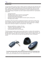
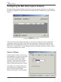
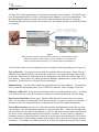
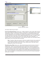
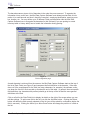
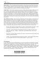
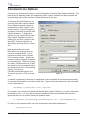
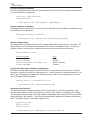
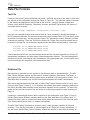
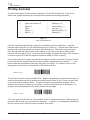
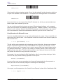
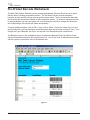
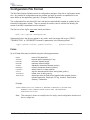
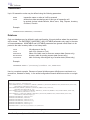
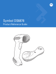
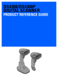
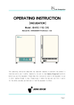
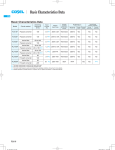
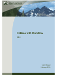
*MEC*
MEC Software
Mini Data Capture System
User Manual
Version 3.0
Mini Data Capture System
User Manual
Version 3.0
© Copyright 2001-2004 Measurement Equipment Corporation
All Rights Reserved
Distributed by:
The Barcode Software Center
1113 Hull Terrace
Evanston, Illinois USA 60202
Tel. 847-866-7940
Fax. 847-866-9836
www.makebarcode.com
Contents
Introduction ............................................................................................................................ 5
Installation .............................................................................................................................. 6
Scanner ....................................................................................................................... 6
Mini Data Capture Software ........................................................................................ 6
Barcode Fonts ............................................................................................................. 6
Configuring the Mini Data Capture Software ......................................................................... 7
Scanner Settings......................................................................................................... 7
Data File ...................................................................................................................... 8
Fields ......................................................................................................................... 10
Field Separator ......................................................................................................... 12
Transactions.............................................................................................................. 13
Loading and Saving Configurations .......................................................................... 14
Capturing and Uploading Data ............................................................................................ 15
Using a Keyboard Wedge Scanner ..................................................................................... 16
The Scanner Simulation Screen .......................................................................................... 17
Command Line Options ....................................................................................................... 18
Data File Formats ................................................................................................................ 20
Text File ..................................................................................................................... 20
Database File ............................................................................................................ 20
Printing barcodes ................................................................................................................. 22
Pre-Printed Barcode Worksheets ........................................................................................ 24
Configuration File Format .................................................................................................... 25
Index .................................................................................................................................... 27
(this page intentionally left blank)
*MEC*
MEC Software
Introduction
The Mini Data Capture System provides an efficient means for reading and storing barcodes using
portable scanners, organizing the data from the barcodes, and uploading the data to a host computer. Capturing data by using barcodes takes less time and produces many fewer errors than
manual data entry. This system can be used effectively in a variety of applications which do not
require portable display or keyboard entry; data is captured using barcodes alone. Typical applications include:
•
•
•
•
•
•
Tracking fixed assets
Recording inventory receipt, movement, and consumption
Collecting equipment serial numbers on service calls
Confirming order fulfilment and shipping
Monitoring customer traffic at ski slopes, amusement parks, sporting events
Recording security incidents
The scanners used by the system are compact and economical. Since they do not have a keyboard or display, every piece of information that they capture must be in the form of a barcode.
Some of these barcodes will be attached to the items to be recorded (asset tags, for example);
others can be carried by the operator on a pre-printed card. For example:
•
•
•
•
Employee identification (on badge or ID card)
Transaction Type (on pre-printed sheet or card)
Location (on shelf/bin/cabinet labels)
Asset Identification (label on the item itself)
The battery-powered scanners capture barcode data and store it in memory until connected to a
computer workstation. The scanners simply store barcodes in the order they were scanned. The
Mini Data Capture software, which runs on a Windows computer, retrieves, organizes, and saves
the data to files. Users can define how data will be organized with a series of configuration
screens.
Figure 1
Two scanner models are available. The CS-1504 “keychain” scanner (left) is a very compact laser device;
it stores about 150 barcodes, includes an internal clock/calendar, and runs on readily-available watch
batteries. The CS-2000 (right) does not have an internal clock, but does have a more powerful laser,
stores as many as 500 barcodes, and runs on two standard AAA batteries.
Mini Data Capture System - User Manual
5
*MEC*
MEC Software
Installation
Scanner
Connect the scanner to an available USB port on the computer. Windows should detect the arrival
of the new device and automatically begin the Add New Hardware wizard. If the wizard does not
begin automatically, it can be started manually by clicking on Start > Control Panel > Add New
Hardware.
When the wizard asks if you wish to specify a driver, click on Browse and navigate to the Mini Data
Capture CD-ROM. Select a folder: USBDriverWin98 if you are running Windows 98 or
USBDriverWin2K if you are running Windows 2000. Then click Next on the wizard screen to proceed with the installation.
First, the USB driver itself will be installed. Next, a new virtual serial port will be installed; this port
will be automatically given the next available serial port number (COM3, for example), and it provides the pathway for application software to communicate with the scanner.
Following installation, you can see the new USB device and COM port by clicking on Start > Settings > Control Panel > System and clicking on Device Manager. This will list the devices known to
the system.
Mini Data Capture Software
Insert the Mini Data Capture System program disk in the computer’s CD-ROM drive and execute
the Setup.exe program. You will be guided through the software installation process.
When the software runs for the first time, a pop-up window will ask for the Installation Key. This
number can be found on a label affixed to the CD-ROM case and on the CD-ROM itself. Enter this
number and click Continue. If you click Cancel, the software will operate in demonstration mode
and will ask you to enter the key each time you start the software.
The first time you use the software, click on the Configuration button to set up the system. See the
section Configuring the Mini Data Capture System beginning on the following page.
Barcode Fonts
If you want to print barcodes, install the Code 39 fonts which are included with the Mini Data Capture System. On the Windows desktop, click on Start > Settings > Control Panel > Fonts. In the
Fonts window, click on File > Add New Font. When prompted for the font file, browse to the CDROM and select all of the files in the Fonts folder.
The software includes a spreadsheet (Microsoft Excel format) for printing barcodes (see Printing
Barcodes, Page 19 for more details).
Mini Data Capture System - User Manual
6
*MEC*
MEC Software
Configuring the Mini Data Capture Software
Run the Mini Data Capture Software and the main screen will appear (see Figure 2); “Demonstration Mode” will appear if the software has been installed without an Installation Key (see Installation,
Page 6):
Figure 2
The main Mini Data Capture screen.
If this is the first time the software has been run, click on the Configuration button to display the
configuration screen (see Figure 3) and make the initial settings. Settings are divided into four
pages which can be displayed by clicking one of the tabs at the top of the page: Scanner, Data
File, Fields, or Transactions. To save changes and return to the main screen, click Done; to return
without saving changes click Cancel;
Scanner Settings
Select the type of scanner you are using
and the serial port to which it is connected
(see USB Driver Installation, Page 6, if
you are using a scanner with a USB
interface). Click on the arrows immediately to the right of the Type and Port
fields to display pull-down lists of choices.
If you want to use a scanner which connects between your keyboard and computer, click the Keyboard Wedge
checkbox (see Page 14 for more details).
Mini Data Capture System - User Manual
7
*MEC*
MEC Software
Data File
The Data File is the final destination for information retrieved from the scanner. The Data File can
be a comma-delimited ASCII text file, a Microsoft Access database, or an Excel spreadsheet. The
Mini Data Capture software records a list of all the data recorded by the scanner, including a
TimeStamp (date and time) and each of the fields you have defined (location and asset tag number,
for example).
11/18/2002 09:33:48,MOV,AP-102,409589
11/18/2002 09:33:58,MOV,AP-102,405533
11/18/2002,09:38:07,MOV,AP-255,405989
c
a
b
d
Figure 4
Barcode data is captured with the portable scanner (a). The Mini Data Capture
software (b) retrieves data from the scanner, organizes it, and records it in
either a comma-delimited text file (c) or a Microsoft Access database (d).
Click the Data File tab on the Configuration screen to display the following settings (see Figure 5):
Type of Data File: Specify the format in which the captured data will be saved. Select Text for a
standard comma-delimited ASCII text format file; each line in a text output file begins with a date/
time stamp, followed by the fields defined in the configuration (see Data File Formats, Page 20, for
more details). Select Access for a Microsoft Access database; captured data is saved as records in
data tables. Select Excel for a Microsoft Excel spreadsheet.
Database Driver: Use this field to select the appropriate driver for your database. The most likely
driver is selected automatically when Type of Data File is selected. Does not apply to Text files.
Pathname of Data File: Enter the drive and folder where your existing data file can be. To browse
to an existing file click on the Browse button to display a standard Windows file selection dialog.
Raw Scanner Data Table (Access only): Specify a table that will be used to store raw scanner
data. You may select an existing table from the scroll-down list or type in a name for a new table. If
the table or any of the required fields do not already exist they will be created automatically.
Post to Main Inventory (Access only): After data has been uploaded and stored in the raw scanner data table, it can be automatically posted to a main inventory table. Select the data table from
the scroll-down list to the right of the checkbox; if you fill in the name of a new table which does not
yet exist it will be created automatically the first time it is needed. A main inventory is typically a
permanent record in which each item or asset has a single record; when posting to the main inventory, the Mini Data Capture software locates the existing record for the item and changes selected
information. For example, the software will look up an item and change the Location field to match
Mini Data Capture System - User Manual
8
*MEC*
MEC Software
Figure 5
Data File configuration settings
the location captured by the scanner.
Post to Chronological History (Access only): As data is posted to a main inventory table, the Mini
Data Capture Software can add the information to a history table, a chronological record of all data
captured by the scanner. Use the Keep a chronological history of all transactions checkbox and
select the data table from the scroll-down list to the right of the checkbox; if you fill in the name of a
new table which does not yet exist it will be created automatically the first time it is needed. Historical information can be useful during an audit or when trying to track down a discrepancy. For
example, the main inventory table contains only the most recent location of an item while the history
table contains a list of every time the item was moved.
Note: If posting to either main inventory or history are enabled, the data in the raw table will
be automatically erased after it has been posted. If posting is not enabled, data will accumulate in the raw data table until the user or other software erases it (see Data Saved in
Database File, Page 15 for more details).
Physical Inventory Table (Access only): Data collected during a physical inventory is stored in a
separate table. Once all of the inventory data has been collected, the contents of the physical
inventory table can be compared to the main inventory table to create a list of discrepancies (the
comparison function is not part of the Mini Data Capture Software). Once discrepancies have been
resolved, the physical inventory table is typically erased in preparation for the next physical inventory. Select an existing table or enter the name of a new table in the field labeled Physical inventory
table. If you fill in the name of a new table which does not yet exist it will be created automatically
the first time it is needed
Mini Data Capture System - User Manual
9
*MEC*
MEC Software
Fields
The barcode scanner stores a list of barcodes in the order they were scanned. To organize the
information into a useful form, the Mini Data Capture Software must determine what kind of information is in each barcode and how it should be recorded: employee identification, asset tag number, location, etc. You may define up to 50 different Fields; each definition tells the Mini Data
Capture Software how to recognize the barcodes for this field and (if you are posting to a main
inventory table or history table) how to handle the information during posting.
Figure 6
Field configuration page
As each barcode is retrieved from the scanner, the Mini Data Capture Software starts at the top of
the list of Data Fields (see Figure 5) and compares the field definition to the barcode. If the data
does not fit the requirements for the field (too many characters, for example), the software continues down the list until it finds a match or reaches the end of the table. In general, the most specific
field definitions (eg. barcodes with prefixes) should go at the top of the list and the more general
definitions at the end.
Click on a field in the Data Fields list to display its details on the right of the screen where you can
edit the settings. To add a new field to the list, just click the Add New button. Clicking the Delete
button will delete the field currently selected on the list (you will be asked for confirmation before the
field is removed). Clicking the Move Up or Move Down button will change the position of a field on
the list.
Mini Data Capture System - User Manual
10
*MEC*
MEC Software
Field Name: This is the name given to each field definition. When saving data to a text file, field
names are not recorded. In Excel, the first row should contain matching field names. When using
Access, the field names should match the fields in the database; if a field with a matching name
does not already exist in the raw scanner data table or in the history table, it will be created automatically. However, the Mini Data Capture Software will not create new fields in a main inventory
table. For example, if you want to update an existing field named CurrentLocation in your main
inventory table, be sure to use the name CurrentLocation for one of the Mini Data Capture Software
field definitions.
Barcode Prefix: This setting defines a fixed prefix that will be found at the beginning of each
barcode for this field. A prefix can be one or more letters or digits, but should be short to avoid long
barcodes. For example, the following barcode includes a LO prefix to indicate that it contains
location data; the prefix is followed by the location (RM107):
*LORM107*
A prefix is a very reliable method for differentiating types of barcodes. Even when the Mini Data
Capture Software recognizes a prefix, to be certain it checks the length of the barcode and whether
letters or numbers are not allowed. You may leave the prefix setting blank, in which case the Mini
Data Capture Software will not expect any fixed prefix and will use other methods (MinLen, MaxLen,
Allow A-Z, Allow 0-9) to identify the barcode.
Strip Prefix: Checking the Strip Prefix box removes the prefix from the data once a barcode has
been classified. While the prefix may be useful to the Mini Data Capture Software for organizing
the data, it may not be recognized by other software that will use the database.
MinLen and MaxLen: The Mini Data Capture Software checks the overall length of the barcode
against MinLen and MaxLen; barcodes which are too short or too long are disqualified, and the
software moves on to the next definition in the Field List. If a prefix is defined, it is not included in
the length calculation. For example, if a barcode contains LORM107 and “LO” is a defined prefix,
the Mini Data Capture Software considers the length to be 5 characters (RM107).
If no prefix is defined, length may be a good way to identify a barcode; serial numbers might always
be exactly 8 digits long, for instance. Even if a barcode contains a prefix, the length check provides
insurance that it will be identified correctly. This is especially true for short prefixes. For example, if
inventory tag barcodes begin with the letter T, there is the risk that some other type of barcode (a
manufacturer’s model number, perhaps) might also begin with a T and be mis-identified. With a
length check, the Mini Data Capture Software can tell the difference between T338478 (an inventory tag) and TBB-449858-AR (manufacturer’s model number). If the length of the barcode is not a
good indicator, set MinLen to 0 and MaxLen to 30 or some other large number.
Allow 0-9 and Allow A-Z: If the Allow 0-9 box is not checked, barcodes that contain any digits will
be disqualified; if the Allow A-Z box is not checked, barcodes that contain any letters will be disqualified. The Mini Data Capture Software will not let you uncheck both boxes, which would disqualify barcodes with any letters or numbers. The prefix, if one exists, is not included in the 0-9 or
A-Z check. For example, an inventory tag field could be defined with a Prefix of TAG and Allow A-Z
unchecked (no letters allowed); the fact that “TAG” includes letters would not disqualify the barcode
because the only letters are part of the prefix.
Mini Data Capture System - User Manual
11
*MEC*
MEC Software
Default Value: This is the value that will be recorded in a field if data is not provided by the scanner. For example, if the default value for Location is set to “Warehouse”, that is the value that will
be saved in the data file if no location barcode is scanned. The default value may be left blank; if
no data is captured by the scanner for that field, the field will be left blank.
Trigger Save?: This checkbox indicates that this type of barcode should trigger a data save operation. In general, only one type of barcode should trigger a save and it should be the last one
scanned; all other barcodes are held in temporary memory until a save is triggered. For example,
presume that Employee and Location barcodes do not trigger a save (Trigger Save unchecked)
and Asset Tag barcodes do; in normal operation the user would scan an Employee and a Location
barcode first, and then scan one or more Asset Tag barcodes. Each time an Asset Tag is scanned,
the Mini Capture Software will record the Asset Tag along with the most-recently scanned Employee
and Location.
Type of Data for posting: Click on the arrow at the right of the field to display a scroll-down list of
choices and select how the data will be handled during posting. This setting does not apply if the
Type of Database is Text File or if Post Updates to the Main Inventory Table is not checked (see
Figure 5, Page 9). The list below describes the available types of data and how they are handled.
If you require posting procedures more complex than those built into the Mini Data Capture Software, it may be best to leave data in the raw data table by unchecking Post to main inventory (see
Figure 5, Page 9) and then use custom software to transfer data to the main inventory table.
ID Tag: Used to look up a unique item by ID number, often fixed assets, file folders, or other
items that are individually identified. Each database record refers to a single item.
Description: General descriptive information such as type of equipment, reason for disposal, sales order, etc. Fields for “Sales Order” and “Purchase Order” could both be
Descriptions.
Employee: The name, initials, employee ID number, or other information which identifies the
person who collected the data.
Location: The physical whereabouts of the item in question. When posting a Move transaction, the software will find the Location field and update it to the new value.
Field Separator
In some applications it may be advantageous to print two or more pieces of information in a single
barcode. Use Field Separator to define a character that will mark the end of one piece of data and
the beginning of another (be sure to choose a character that will not appear in the data). For
example, assume that Part Number barcodes begin with the prefix PN and Quantity barcodes begin
with QT. Setting Field Separator to a slash character ( / ) permits a single barcode to contain both
pieces of information. The Mini Data Capture Software will treat the following barcode as two
separate entries (Part Number = 12345, Quantity = 25):
*PN12345/QT25*
Mini Data Capture System - User Manual
12
*MEC*
MEC Software
Transactions
Transaction barcodes identify the situation in which data was collected. For example, the user may
move several items from one location to another, and then receive new items into inventory. The
Mini Data Capture Software uses transaction information when posting to a main inventory table
(Post to main inventory checked; see Figure 4, Page 9). Even if posting is not enabled, transaction
Figure 7
Transactions Page
codes are still recorded in text files, raw scanner tables, and history tables.
A data collection sequence typically begins with a transaction barcode. For example, if you intend
to move items to a new location, scan a Move transaction barcode followed by a location and then
several asset tags. Up to ten transaction codes may be defined.
Transaction Code: The word or abbreviation that will appear in the barcode and identify the type
of transaction. The codes should be reasonably short in the interest of compact barcodes. For
example, for taking physical inventory the code “INV” used in Figure 7 would be better than
“TAKEPHYSICALINVENTORY”.
Function: This field tells the Mini Data Capture Software how to handle this type of transaction
when posting information to the main table. The following functions are available:
Move:
Receive:
Ship:
Dispose:
Check Out:
Check In:
Inventory:
Look up the item and change its current location
Add a new record to the system.
Look up the item and reduce the quantity on hand
Look up the item and set its quantity to zero.
Look up the item, mark as checked out, and update the employee and location fields
Look up the item and mark as checked in
Collect data in a separate physical inventory table
Mini Data Capture System - User Manual
13
*MEC*
MEC Software
Loading and Saving Configurations
All of the settings described in Configuring the Mini Data Capture Software (Pages 7-13) are saved
in a configuration file. You may create any number of configurations with different settings for
barcode prefixes, data files, etc. Each configuration is saved in a separate file in the Mini Data
Capture Software’s home directory (the files are named with a .cfg extension).
When Mini Data Capture runs for the first time, it automatically loads the standard configuration:
Default.cfg. The name of the currently-loaded configuration is displayed in the top left corner of the
configuration screen. To load a different configuration, click on Load New Configuration (see Figure
5, Page 9) to display the Select Configuration File screen (see Figure 8, below). Click the scrolldown arrow to display a list of available configurations, including samples shipped with the software
and any new configurations that you have created. The Mini Data Capture Software will automatically load the most recently used configuration each time it starts.
Figure 8
Select Configuration File screen
Once you have modified the configuration, click Done (see Figure 5, Page 9) to save the configuration under its original name. This will replace the previous settings stored in that file. If you prefer
to save the configuration under a new name, click Save Config As (see Figure 5, Page 9) to display
the Save Configuration As screen (see Figure 9, below). The software will ask for a new name and
save the configuration in a new file; the original configuration file will not be altered.
Figure 9
Save configuration under a new name
Mini Data Capture System - User Manual
14
*MEC*
MEC Software
Capturing and Uploading Data
As an example, let’s track fixed
assets (computers, monitors, desks,
etc.) using the three fields shown in
Figure 6 on Page 10: Transaction,
Location, and AssetTag. These
barcode types are typical for a fixed
assets tracking application. Every
asset should be identified with an
AssetTag barcode. Location
barcodes can be affixed to door
jams and cubicles, or the user can
carry a barcoded list of locations.
Transaction barcodes are typically
printed on a sheet of paper or card
carried by the user.
Figure 10
Let’s assume that a major re-organization is underway, with equipment
and furniture being moved throughout the facility; the user is charged with the task of updating the
locations recorded in the central database. To begin, the user would scan a Move transaction
barcode. Next the user would choose a place to start and scan its Location code. Then the user
would scan the AssetTag for everything in that location. Only the AssetTag field is checked to
trigger a save (see Trigger Save, Page 10). Each time an AssetTag is scanned, that information
and the most-recently scanned location and transaction are recorded. Each saved record will
contain the transaction code, location, asset tag number, and a date/time stamp.
To move on to another location, the operator would scan a new location code followed by more
asset tags. The previously-scanned transaction code remains in effect until a new transaction code
is scanned.
Note that data is not saved until a barcode which is configured for Trigger Save is scanned (see
Page 8); until the data is saved it is kept in temporary registers. Each time a barcode is scanned,
the new data replaces the contents of the temporary register for that type of barcode. To clear all of
the temporary registers for a clean start, scan the special command barcode (below); data which
has already been saved is not affected. The barcode contains the special prefix (“CMD”) and a
command (“CLEAR”):
*CMDCLEAR*
To transfer the collected data from the scanner to the computer, click Read Scanner (see Figure 2,
Page 7). The Mini Data Capture Software will communicate with the scanner, upload and process
the data, and then automatically erase the scanner’s memory. To transfer the data from the screen
to the database or text file, click on Save Data (see Figure 2, Page 7). If the software is running in
demonstration mode, one character in every data field will be changed at random when it is transferred to the database.
Mini Data Capture System - User Manual
15
*MEC*
MEC Software
Using a Keyboard Wedge Scanner
If Use Keyboard Wedge Scanner is checked on the scanner configuration screen (see Figure 3,
Page 7), the main display will include data entry fields for keyboard entry. You may enter data
manually or with a keyboard wedge scanner which is wired to the computer’s keyboard port.
The entry fields are based on the fields defined in the configuration pages. Here is a sample where
we have defined three fields: Transaction, Location, and Asset Tag (the TimeStamp field is filled in
automatically using the system clock and is not shown as one of the data entry fields):
Figure 11
Main screen with keyboard wedge scanner enabled
When data is entered in any of the fields, the Mini Data Capture Software checks it against the
configuration to see if it can identify what type of data it is. For example, if you have specified in the
configuration that Transaction barcodes always begin with “TR” and you enter TRMOVE, the data
will be automatically placed in the Transaction field even if the keyboard cursor was in a different
field when you entered the data.
If the software cannot identify the data, it leaves it in the field where the keyboard cursor was
located when the data was received. If the field is incorrect, the operator may erase the field and
rescan the data, or cut and paste the data into the correct field.
Entering data in a field which is marked in the configuration to Trigger Save causes the data to be
transferred to the grid on the display. You may enter data from the keyboard, a keyboard wedge
scanner, or from a portable scanner; all of the data will appear on the data grid and then be transferred to the database when you click Save Data.
Mini Data Capture System - User Manual
16
*MEC*
MEC Software
The Scanner Simulation Screen
The scanner simulation screen appears when Simulate Scanner is clicked or when Read Scanner is
clicked and the software is operating in demonstration mode(see Figure 2, Page 7). This screen is
used to demonstrate how the scanner collects data; it can also be very useful for testing and refining configurations and for training. Data collected on the simulation screen is processed and
posted to a database just as though it had come from a scanner; configurations created and tested
with the simulation screen should work exactly the same way with a real scanner.
Figure 12
To create simulated “barcodes”, type data into any of the 20 entry fields on the left half of the
screen. Don’t forget to include barcode prefix characters if you have defined them in the configuration. The Mini Data Capture Software will remember these entries and display them the next time
you use this screen. To “scan” a barcode, double-click on its entry field; the data will appear on the
list at the right of the screen which simulates the scanner’s memory.
The portable scanner has two scan buttons: one for scanning barcodes, the other, smaller button
to erase them from memory. Click on Normal Button or on Delete Button to select which button is
being simulated. To erase a barcode, select Delete Button and then “scan” (double click) the
barcode which is to be erased. The most recent “scan” of that particular barcode will be erased
from memory (this simulates the way the real scanner works). To erase the entire list, click on
Erase List; this performs the same function as holding the scanner’s delete button down for 6
seconds. Click Done to return to the main screen.
Mini Data Capture System - User Manual
17
*MEC*
MEC Software
Command Line Options
Command line options can be used to control the behavior of the Mini Data Capture Software. This
feature can be especially useful for integrating the Mini Capture Software into larger systems and
for automating some of the functions normally performed by the user.
A command line tells Windows to execute the Mini Data Capture software.
Every Windows shortcut contains a
command line, called “Target” on the
shortcut screen. Figure 13 shows an
example of a shortcut to the Mini Data
Capture Software. To display this
shortcut on your system after the Mini
Data Capture Software has been installed, click on Start, Programs, and
then MEC Software; right-click on
MiniCapture and then click on Properties.
Note that the pathname to the
MiniCapture.exe program file is enclosed in quotation marks. This is
because the folder name “Program
Files” contains a space. Spaces are
normally used as separator characters
on command lines. Without the quotation marks, Windows would try to split
the pathname into two separate items
and would not be able to find anything
named C:\Program or
Files\MiniCapture\MiniCapture.exe.
The result would be a “File not found”
error.
Figure 13
In addition to appearing in shortcuts, the pathname to the executable file can be entered manually
at command line prompts or included in batch files. Options follow the pathname to the executable
on the command line:
<Pathname to Executable file> <options>
For example, the command line below tells the Mini Data Capture Software to use the configuration
file named MYTEST.CFG; note that the option is separated from the executable pathname by a
space and that it is not included inside the quotation marks.
“C:\Program Files\MiniCapture\MiniCapture.exe” /config=MYTEST.CFG
For clarity in the examples below, we have shortened the executable pathname to:
...\MiniCapture.exe
Mini Data Capture System - User Manual
18
*MEC*
MEC Software
Log on to protected databases
Use the following parameters when the host database which will receive the captured data requires
a user identification and password:
/uid=<user identification>
/pwd=<password>
...\MiniCapture.exe /uid=joedoaks /pwd=holycow
Specify pathname to database
A database location other than the one defined in the Mini Data Capture Software configuration may
be specified with this parameter:
/database=<database pathname>
...\MiniCapture.exe /database=M:\Shared\Inventory.mdb
Specify database driver
The data provider is software installed on the system that provides orderly access to the data. The
default provider for Microsoft Access databases is Microsoft’s Jet database engine. To specify a
different provider, use this option; examples of some commonly-used drivers are shown:
/driver=<driver name>
Command Line Option
Driver
/driver=SQLOLEDB
/driver=MSDASQL
/driver=Microsoft.Jet.OLEDB.3.51
/driver=MSDAORA
(SQL)
(ODBC)
(MS Jet (default))
(Oracle)
Specify Mini Data Capture Software configuration
By default, the Mini Data Capture Software will use the configuration that was used last. Use this
parameter to specify the name of a configuration file. You may specify a complete pathname; if you
specify only a filename, the software will automatically try to find it in the program directory (probably C:\Program Files\MiniCapture).
/config=<name of configuration file>
...\MiniCapture.exe /config=JobTrack.cfg
Automate upload and exit
The Mini Data Capture Software normally waits for the operator to initiate the uploading of data.
Use the Upload option to cause Mini Capture to connect to the scanner immediately upon starting.
The Post option transfers data to the host database immediately after uploading it from the scanner
without waiting for the operator. The Exit option terminates the program immediately after posting
data. The default setting for all of these options is No.
/upload=<yes/no>
/post=<yes/no>
/exit=<yes/no>
...\MiniCapture.exe /upload=yes /post=yes /exit=no
Mini Data Capture System - User Manual
19
*MEC*
MEC Software
Data File Formats
Text File
If data is to be saved in comma-delimited text format, the fields are saved in the order in which they
are defined on the configuration screen (see Figure 6, Page 10). The date/time stamp is recorded
by the scanner and appears as the first field on the text line. Using the sample configuration
screens, which defines Employee, Transaction, Location, and Asset Tag barcodes, the format of
each data record would be:
<time stamp>,<employee>,<transaction>,<location>,<tag>
Here are some sample records which assume that Mr. Jones scanned his identification badge, a
MOVE transaction barcode, the location barcode on the door frame at Room 102, and then in rapid
succession two asset tags. He then moved to Room 103, scanned the location barcode, and then
scanned one asset tag. Since the TAG field is checked for Trigger Save, each tag caused data to
be written to the disk file. All of the other registers retain their value until replaced by a new scan.
2/5/2001 09:15,JONES,MOV,RM102,56698
2/5/2001 09:15,JONES,MOV,RM102,66958
2/5/2001 09:15,JONES,MOV,RM103,66339
Comma-delimited ASCII text is a standard data format and can be easily imported into virtually all
spreadsheets, databases, and other types of data management software. The data management
software can build a chronological log of transactions; using appropriate code, it can interpret each
record according to the transaction code and post the data.
Database File
Barcode data is uploaded from the scanner to the Raw data table in the database file. The Mini
Data Capture Software expects the Raw table to include a date/time field named TimeStamp. It
also expects to find data fields with the same names as defined in the configuration screen. If the
Raw table does not already exist, the Mini Data Capture Software will create it automatically.
After storing barcode data in the Raw table, the Mini Data Capture Software looks at Post to main
inventory (see Figure 5, Page 9). If it is checked, the software then makes changes or additions to
the data in the Main table according to the information captured from the scanner. For more information on how the data is posted, see the section on configuring transaction codes beginning on
Page 13.
If posting to a chronological History table is specified in the configuration (see Figure 5, Page 9),
the Mini Data Capture Software transfers data from the Raw scan table to the History table. It
expects the History table to contain field names which match the ones used in the Raw scan table.
If the History table does not exist it is created automatically.
The Mini Data Capture Software then checks to see if a table has been specified for Physical
Inventory. If so, the Raw scan table is checked again for any Physical Inventory transactions. If
any are found, the Mini Data Capture Software updates the location for items that are already on
Mini Data Capture System - User Manual
20
*MEC*
MEC Software
the Physical Inventory table and creates new records for those that are not. If no Physical Inventory
table is specified, any captured physical inventory records will remain unposted in the Raw scan
table.
If posting to either the Main or History tables is enabled, the Mini Data Capture Software will automatically delete records from the Raw table after they are posted. If no posting is specified, data is
left on the Raw table with the expectation that it will be processed and then deleted by other software.
Note: It is important that the database file not be locked by another program or otherwise unavailable to the Mini Data Capture Software. To insure that Microsoft Access data tables are shareable,
use two .mdb (Access) files for every database application. One .mdb file should contain only data
tables and should be stored on a shared network disk drive (there should be only one copy of this
database). The other .mdb file contains the queries, forms, reports, and code modules, plus links to
the data tables which are actually located in the first file. In Access, click on File -> Get External
Data -> Link Tables. This structure permits simultaneous access to the data by several programs.
A further word about physical inventory... To take a physical inventory, start by removing any
existing records in the physcial inventory table; you may wish to make an archive copy of the existing records for future reference. Next, use the Inventory transaction code and scan locations and
all assets found in those locations. Depending on the size of the organization, this may take hours
or days.
As data is uploaded, the Mini Capture Software stores physical inventory data in a separate data
table (information in the main inventory table is not changed). When you think every asset has
been recorded, compare the Physical Inventory table and the Main table. In Microsoft Access this
can be done with a few simple queries that detect assets which have not been found or are in an
unexpected location. If everything is in the proper place, the physical and main tables should agree
with no discrepancies to report.
Once a physical inventory is complete and all discrepancies are resolved, the physcal inventory
records may, if desired, be archived and the physical inventory table cleared in preparation for the
next inventory cycle.
Mini Data Capture System - User Manual
21
*MEC*
MEC Software
Printing barcodes
The Mini Data Capture System includes a selection of Code 39 TrueType fonts. Code 39 is a
widely-used, general-purpose type of barcode which includes the following characters:
•
•
•
•
•
•
•
•
•
•
upper case letters A-Z
digits 0-9
space
hyphen ( - )
period ( . )
dollar sign ( $ )
forward slash ( / )
plus sign ( + )
percent symbol ( % )
start/stop (*)
Figure 14
Code 39 Character Set
Code 39 is variable length and can contain any reasonable number of characters. In practice,
barcodes with more than 15 or 20 characters begin to be a little long. The point size used must be
large enough so that the scanner can resolve the individual bars; 24 points is a good minimum
size. Bear in mind that inkjet images tend to spread, so you may not be able to make smaller
barcodes with this type of printer. As to the maximum length, remember that many of the scanners
in common use are CCD devices with fixed maximum widths (3 inches is typical).
Code 39 barcodes do not require any special formatting or checksum calculation, but they do have
to start and end with a special start/stop character which is represented by an asterisk ( * ). Just
print the data with an asterisk at each end, using the Code 39 font. For example, here is a text
string and the result when it is printed with a Code 39 barcode font:
*ABCD1234*
*ABCD1234*
This will be read by the scanner as ABCD1234. Without the asterisks the barcode will not scan; be
sure that the asterisks as well as the data are printed with the Code 39 font. Never use bold, italic,
or any other special character effects. The space character requires special handling. When
Windows sees a space character in a text string, it inserts a blank white spot in the printout. For
example, the following barcode has a space character in the middle:
*ABCD 1234*
*ABCD 1234*
This is not good for a barcode; we need a pattern of bars to represent the space. When a space is
required in the barcode, use the underscore character ( _ ) instead. It is automatically translated by
the font into the correct Code 39 barcode character for a space.
Mini Data Capture System - User Manual
22
*MEC*
MEC Software
*ABCD_1234*
*ABCD_1234*
If the barcode includes rectangles instead of bars, the data probably includes characters which are
not part of the standard Code 39 selection. For example, the following barcode is not scannable:
*ABCDë1234*
*ABCDë1234*
Lower case letters a-z are not part of the Code 39 character set, but they are automatically translated to upper case characters by the font.
You can use the barcode fonts in almost any type of Windows-based software, such as spreadsheets, word processors, and database reporting programs. Caution: Beware of auto-formatting
features in some software; Microsoft Word 2000, for example, automatically treats a pair of asterisks as a command to format the enclosed data as Bold text (you can turn this “feature” off).
Using Barcodes with Microsoft Access
If you are using Microsoft Access, you can easily add barcodes to a report. Set up a text field and
select one of the Code 39 fonts. In the Properties for the field, edit the Control Source Property so
that it looks like this:
= ”*” & [MyFieldName] & “*”
This will add the required asterisks at the beginning and end of the data. Access may not always
interpret complicated expressions which are embedded in the Control Source Property. For example, you may see an Err message if you try to put a numeric field (long integer, integer, double,
etc.) between the asterisks. If you try to use a Str$() or Format$() function in the Control Source
Property, Access may object. The best solution may be to use a query as the source of the data
and perform the numeric to string conversion in the query.
For example: the query includes the field CaseNumber, which is a long integer data type. Add a
column to the query with the following expression in the top row:
Format$([CaseNumber])
As soon as the cursor moves somewhere else, Access will automatically give the expression a
name (this name can be manually changed to something more descriptive):
Expr1:Format$([CaseNumber])
In the report, use this expression in the Control Source Property in place of the CaseNumber field:
= “*” & [Expr1] & “*”
Mini Data Capture System - User Manual
23
*MEC*
MEC Software
Pre-Printed Barcode Worksheets
The Mini Data Capture Software includes sample spreadsheets (Microsoft Excel format) to assist
with the task of creating pre-printed barcodes. The first sheet includes several transaction
barcodes and the second includes several typical location codes. The list of transaction barcodes
should match the transactions defined on the configuration screen. To add more transaction codes
to the spreadsheet, just copy and paste one of the existing lines and then change the Description
and Code settings; the barcode will update automatically.
To create additional sheets, click on Edit > Copy or Move Sheet. Check the Create Copy box and
specify where the new copy should be inserted (probably after the last sheet currently in use). Then
change the Type of Barcode, the Prefix, and edit the list of Descriptions and Codes/Values.
The Barcode column in the spreadsheet simply combines the Barcode Prefix cell with the Code/
Value cell and adds asterisks at the beginning and end. One of the Code 39 barcode fonts included
with the system is used as the font for the barcode cells.
Figure 15
Mini Data Capture System - User Manual
24
*MEC*
MEC Software
Configuration File Format
The Mini Data Capture Software saves its configuration settings in files with a .cfg filename extension. Any number of configurations can be created, and each is stored in a separate file in the
same folder as the application (typically C:\Program Files\MiniCapture).
The configuration files are plain ASCII text, and they are automatically created or updated by the
interactive configuration screen. There is normally no need to view or edit the files directly; the
syntax of the files is described here for reference.
The first line of the .cfg file must read exactly as follows:
Mini Data Capture Configuration
Subsequent lines in the file may appear in any order; each line begins with a type (“FIELD”,
“TRANASCTION”, or “DATABASE”) followed by parameters in the following format:
<type>:<parm1>=<value>,<parm2>=<value>, ... <parmn>=<value>
Fields
Up to 50 data fields may be defined using the following parameters:
NAME
PREFIX
MINLEN
MAXLEN
ALPHA
NUMERIC
DEFAULT
STRIP
INITSAVE
FUNCTION
name of this data field
barcode prefix character(s) if any
minimum allowed length
maximum allowed length
alphabetic characters allowed (yes/no)
numeric characters allowed (yes/no)
default value if no data scanned
strip the barcode prefix before saving data (yes/no)
initiate save of data (yes/no)
determines how the field will be handled when posted; choices
include Description, Employee, ID Tag, Location, Part Number,
Quantity, Transaction.
Example:
FIELD:NAME=Location,PREFIX=L,MINLEN=0,MAXLEN=30,ALPHA=YES,
NUMERIC=YES,DEFAULT=MAIN,STRIP=YES,INITSAVE=NO,
FUNCTION=Location
Note: This example is shown on multiple lines for clarity; actual configuration entries must
be on a single line.
Mini Data Capture System - User Manual
25
*MEC*
MEC Software
Transactions
Up to 10 transaction codes may be defined using the following parameters:
NAME
TYPE
transaction name or code as it will be scanned
defines how data recorded as part of this type of transaction will
be posted; choices include Receive, Move, Issue, Ship, Dispose, Inventory,
Checkout, Checkin.
Example:
TRANSACTION:NAME=MOV,TYPE=Move
Database
Only one database may be defined in each configuration; this entry defines where the saved data
will be stored. The RAWTABLE, MAINTABLE, and LOGTABLE parameters only apply in the case
of Access databases. MAINTABLE and LOGTABLE parameters are ignored unless data is to be
posted to the main inventory table or to a history table.
PATH
TYPE
RAWTABLE
MAINTABLE
LOGTABLE
full pathname to the file
type of file (Access or Text)
name of the table used to store raw scanner data (Access only)
inventory table for posting scanner data (Access only)
table for storing chronological log of scanner data (Access only)
Example:
DATABASE:PATH=c:\Inventory\scandata.txt,TYPE=Text
Here is a complete example. Because of space limitations some definitions are continued on a
second line, indented for clarity. In the actual configuration fileeach definition must be on a single
line.
Mini Data Capture Configuration
FIELD:NAME=Transaction,PREFIX=T,MINLEN=0,MAXLEN=30,ALPHA=YES,NUMERIC=YES,DEFAULT=MOVE,STRIP=YES,
INITSAVE=NO,FUNCTION=Transaction
FIELD:NAME=TAG,MINLEN=4,MAXLEN=4,ALPHA=NO,NUMERIC=YES,STRIP=NO,
INITSAVE=YES,FUNCTION=ID Tag
FIELD:NAME=Location,PREFIX=L,MINLEN=0,MAXLEN=30,ALPHA=YES,NUMERIC=YES,DEFAULT=MAIN,STRIP=YES,
INITSAVE=NO,FUNCTION=Location
FIELD:NAME=User,PREFIX=U,MINLEN=0,MAXLEN=30,ALPHA=YES,NUMERIC=YES,DEFAULT=NONE,STRIP=YES,
INITSAVE=NO,FUNCTION=Employee
TRANSACTION:NAME=CKI,TYPE=Checkin
TRANSACTION:NAME=MOV,TYPE=Move
TRANSACTION:NAME=CKO,TYPE=Checkout
TRANSACTION:NAME=INV,TYPE=Inventory
TRANSACTION:NAME=RCV,TYPE=Receive
TRANSACTION:NAME=DIS,TYPE=Dispose
DATABASE:PATH=c:\Inventory\scandata.txt,TYPE=Text
Figure 16
Mini Data Capture System - User Manual
26
*MEC*
MEC Software
Index
A
M
Allow 0-9 11
Allow A-Z 11
MaxLen 11
Microsoft Access 8
MinLen 11
B
P
Barcodes
Font Installation 6
Prefixes 11
Printing 22
Strip prefix 11
Worksheet 24
Physical Inventory Table 9
Posting to database 8
R
Raw table 8
C
S
Command line options 18
Configuration 7
Allow A-Z, Allow 0-9 11
Data Fields 10
Data File 8
Default Value (field) 12
MaxLen 11
MinLen 11
Scanner 7
Trigger Save 12
Scanner configuration 7
Strip Prefix 11
T
Tranactions
Codes 13
Transactions
Functions 13
Trigger Save 12
Type of Data (field) 12
D
Data file configuration 8
Database File
Format 20
Specifying location 8
Default value for data fields 12
F
Field Name 11
Field separator 12
Fields, configuration 10
Function (transaction configuration) 13
H
History Data Table 9
I
Installation 6
Introduction 5
K
Keyboard wedge scanner
Scanner, keyboard wedge 16
Mini Data Capture System - User Manual
27