1
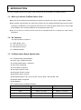
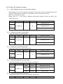
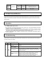
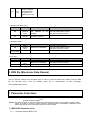
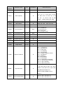
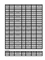
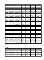
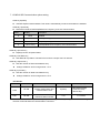
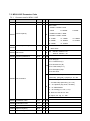
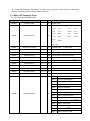
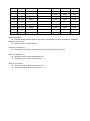
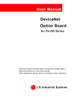
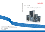
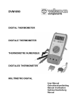
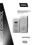
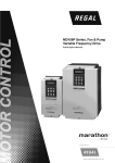
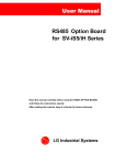
User Manual PROFIBUS-DP Option board MDLV-100P Series Marathon Drives Read this manual carefully before using the PROFIBUS-DP Option board and follow the instructions exactly. After reading this manual, keep it at handy for future reference. Regalbeloit Australia Thank you for purchase of MD100P Profibus-DP Option Board! SAFETY PRECAUTIONS Always follow safety precautions to prevent accidents and potential hazards from occurring. Safety precautions are classified into “WARNING” and “CAUTION” in this manual. Indicates a potentially hazardous situation which, if not WARNING CAUTION avoided, can result in serious injury or death. Indicates a potentially hazardous situation which, if not avoided, can result in minor to moderate injury, or serious damage to the product. Throughout this manual we use the following two illustrations to make you aware of safety considerations: Identifies potential hazards. Read the message and follow the instructions carefully. Identifies shock hazards. Particular attention should be directed because dangerous voltage may be present. Keep this manual at handy for quick reference. CAUTION Do not touch the CMOS components unless the board is grounded. ESD can cause break down of CMOS components. Do not change the communication cable with the inverter power is turned on. Otherwise, there is a danger of connecting error and damage to the board. Make sure to precisely insert the connector of inverter and option board Otherwise, there is a danger of connecting error and damage to the board. Check the parameter unit when setting the parameters. Otherwise, there is a danger of connecting error and damage to the board. Connect terminal resistor at the last connected option board. 1. INTRODUCTION By using a Profibus Option board, MDLV-100P inverters can be connected to a Profibus network. 1.1. When you use the Profibus Option Card … Drive can be controlled and monitored by the sequence program of the PLC or other master module. With a single communication line, multi-units of drives can be operated simultaneously with each other, reducing the installation cost compared to that case of non-communication system set up. Also, simple wire installation can cut down installation and maintenance labor hours. Able to use PLCs to control the drive and can be integrated with PC to simplify the Total Factory Automation. 1.2. Kit Contents The option board kit consists of: Option Board, 1 pcs 9 pin Connector, 1 pcs Mounting poles, 3 pcs Installation Manual 1.3. Profibus Option Board Specification 1.3.1 Communication specification Device Type: Profibus DP Slave Auto Baud Rate Detect : Supported Sync Mode: Supported Freeze Mode: Supported Max Input Length: 8 words Max Output Length: 8 words Max Data Length: 16 words Baud Rate Support: 9.6K, 19.2K, 93.75K, 187.5K, 500K, 1.5M, 3M, 6M, 12M Modular Station: Supported Max Module 2 1.3.2 Communication available distance Communication speed(bps) Max segment length Max extention distance 9.6k ~ 187.5k 1000 m / 3278 feet 10000 m / 32786 feet 500k 400 m / 1311 feet 4000 m / 13114 feet 1.5M 200 m / 655 feet 2000 m / 6557 feet 3M ~ 12M 100 m / 327 feet 1000 m / 3278 feet 2. Layout and Installation 2.1 Layout Terminal resistor S/W ON Inverter interface connector LED D4 OFF J1 PROFIBUS-DP interface LED D3 D2 D1 A1 B1 S1 A2 B2 S2 Mounting poles Fig 1. Layout 2.1.1 Status LED Interface LED with drive Active when the communication between drive and Profibus Option Module LED(D1) is operating correctly. Heart beat LED(D2) LED is ON with 1 sec period while option board has no problem it self. LED is ON with 1 sec period while it has different In/Out number of Master Error LED(D3) Profibus status and Inverter.. communication LED(D4) Active when status of Profibus is operating correctly. * Please refer to “5. Troubleshooting” for further details. 2.1.2 Communication Terminal A1 Pin No. Description B1 A1 B1 Receive/ Receive/ Transmit Data Transmit Data Plus Negative S1 S1 Shield A2 B2 S2 A2 B2 Receive/ Receive/ Transmit Data Transmit Data Plus Negative S2 Shield 2.1.3 Terminal resistor setting Connect inner terminal resistor by trrigering Switch J1 when it is used at terminal. ON OFF ON J1 Case that connecting resistor OFF J1 Case that Not connecting resistor 2.2 Installation 2.2.1 Installing Profibus board on Inverter board Fig 2. Installing MDLV-100P Profibus DP on Inverter board Fig 3. Installing MDLV-100P Profibus DP on Inverter board 2.3 Profibus DP Parameter Setting 2.3.1 MAC ID(Media Access Control Identifier) Setting 1. MAC ID(Media Access Control Identifier) has different unique value which can distinguishing the each Node in Profibus Network. Therefore, it is impossible to share at each different device. 2. MAC ID is changable by Keypad. 3. Default value is “1”. If any trouble in DPRAM communication between inverter and option card, default value is 127. Inverter Display Minimum Maximum Parameter Location COM Group, # 20 MDLV100P Profi MAC ID 1 127 COM Group, # 20 EXT_09 2.3.2 Setting the Number of output Data 1. Setting the number of monitoring data Inverter Display Minimum Maximum Parameter Location COM Group, # 30 MDLV100P OutPut Num 1 8 COM Group, # 30 EXT_10 2.3.3 Setting the number of input data 1. Setting the number of external command data Inverter Display Minimum Maximum Parameter Location COM Group, # 40 MDLV100P InPut Num 1 8 COM Group, # 40 EXT_19 2.3.4 Setting the addresses of output data 1. Setting the addresses as many as the number of output data. Inverter MDLV100P 2.3.5 Display OutPut 0~7 Minimum Maximum Parameter Location 0000h FFFFh COM Group, # 30~38 0000h FFFFh COM Group, # 31~38 0000h 7C3Bh EXT_11~18 Setting the addresses of input data 1. Setting the addresses as as many as the number of input data. Inverter Display Minimum Maximum Parameter Location MDLV- InPut 0~7 100P 0000h FFFFh COM Group, # 41~48 0000h FFFFh COM Group, # 40~48 0000h 7C3Bh EXT_20~27 3 I/O Data Transmit/Receive Output data set by Keypad is transmitted to Profibus Master Module (PLC or PC) through Profibus Option Module. On the contrary, input data is received from Profibus Master Module(PLC or PC) through Profibus Option Module. 4 Operation 4.1 When power-up or reset. After self-testing, Heart beat LED(D2) blinks when no fault occurs . If any fault is detected, Heart beat LED(D2) is off or Error LED(D3) is turned on. After trying to get correct configuration parameter (Station Address, Out data No, In Data No, Out Data Address1~8, In Data Address1~8 set by Keypad) by DPRAM with drive, configure profibus and start the communication. Interface LED(D1) blinks whenever communicating to drive. Profibus communication status LED(D4) is deactivated when communication with Master starts as correct configuration. 5 Troubleshooting LEDs (Profibus communication status LED, Interface LED with drive, Heart beat LED, Error LED) indicate the status of device and network. < Profibus communication status LED(D4) > LED Status Cause Misconnection with connector There is no MASTER in this network Off OffLine Help Check pin number of connector and connection of terminate resistor Check master status or master existence Wrong address Check the address in Keypad is equal to that of MD100P Profibus Option Module using Configuration Tool, and unique number in network. Network Configuration problem Check the maximum length of segment. Check the numbers of node include repeater in segment. Number of node must be 32 or above in segment. Check the numbers of node include repeater in Network. Number of node must be 126 or above in network. OnLine On Network, address, Parameterization, Configuration is operating correctly. < Interface with drive LED > LED Status Cause Help Off DPRAM Interface error Interface between drive and DPRAM is not available. On Normal Check the power of drive. Check the fault status of drive. Check the connector to drive Operating correctly < Heart Beat LED > LED Off Blink about 1 sec period Status Option Module error Cause Operating of option Module is not available Normal Operating correctly Help Check the power of drive. Check the fault status of drive. Check the connector to drive < Error LED > LED On Off Status Option Module error Normal Cause Help Operating of option Module is not available. Check the fault status of drive. Check the connector to drive. Operating correctly 6 EDS file (Electronic Data Sheets) This is a file that contains drive parameter data. In order to control the parameter of MDLV-100P, the EDS file for iS5/100P drive must be installed (EDS file is downloadable at MD Homepage www.regalaustralia.com.au) 7 Parameter Code (Hex) Common Area: Area accessible regardless of inverter models, There are some address for special Inverter model.(Note1) Note1) The changed value in Common affects the current setting but returns to the previous setting when power is cycled or Inverter is reset. However, changing value is immediately reflected in other parameter groups even in the case of Reset or Power On/Off. 7.1 MDLV-iS5 Parameter Code 7.1.1 Common area for MDLV- iS5 Parameter Address 0x0000 Parameter Name Unit Read/Write Drive model - R Data Value (Hex) 4: MDLV-iS5 0: 0.75 5: 7.5 0x0001 Drive capacity - R 30 1:1.5 6: 11 2:2.2 7: 15 8: 18.5 B:37 C:45 10: 110 14:220 - R 0: 220V 1: 440V 0x0003 S/W Version - R 0100: Ver. 1.00, 0x0005 Frequency Reference 0.01Hz R/W - R/W 0x0007 Acceleration Time 0.1 sec R/W 0x0008 Deceleration Time 0.1 sec R/W 0x0009 Output Current 0.1 A R 0x000A Output Frequency 0.01 Hz R 0x000B Output Voltage 0.1 V R 0x000C DC Link Voltage 0.1 V R 0x000D Output Power 0.1 kW R 0x000E Sequence Monitor - R D: 55 E: 75 F: 90 15:280 16:375 (Unit : kW) Drive Input Voltage Run Command 9: 22 A: 11: 132 12: 160 13: 200 0x0002 0x0006 3: 3.7 4: 5.5 0101: Ver 1.01 Bit 0: Stop Bit 1: Forward Run Bit 2: Reverse Run Bit 3: Fault Reset Bit 4: Emergency Stop BIT 0 : Stop BIT 1 : Forward Run BIT 2 : Reverse Run BIT 3 : Fault (Trip) BIT 4 : Accelerating BIT 5 : Decelerating BIT 6 : Output Frequency Arrival BIT 7 : DC Braking BIT 8 : Stopping BIT 9 :Not Available BIT 10 : BrakeOpen BIT 11: Forward Run Command BIT 12 : Reverse Run Command BIT 13 : Rem, Run/Stop BIT 14 : Rem, Freq. Cmd Bit 0:OCT1, Bit 1: OV, Bit 2: EXT-A Bit 3: BX, Bit 4:OCT2, Bit 5: GF, Bit 6: 0x000F Trip information - R OH,Bit 7: ETH, Bit 8: OLT, Bit 9: HWdiag,Bit10:EXT-B,Bit11:FO Bit12:OPT,Bit13:POBit,14:IOLT, Bit15:LV 0x0010 Input Terminal Status - R Bit 0: P1, Bit 1: P2, Bit 2: P3 Bit 3: P4, Bit 4: P5, Bit 5: P6, Parameter Parameter Name Address Unit Read/Write Data Value (Hex) Bit 6: RST, Bit 7: BX, Bit 8: JOG, Bit 9: FX, Bit 10: RX Bit 0: Q1 (OC1) , Bit 1: Q2 (OC2) Output Terminal 0x0011 - Status R Bit 2: Q3 (OC3), Bit 3: AUX Bit 4: 30AC 0x0012 V1 - R 0000h – FFC0h 0x0013 V2 - R 0000h – FFC0h 0x0014 I - R 0000h – FFC0h 0x0015 RPM - R 7.1.2 MDLV-iS5 Function code < DRV Group > Address No. Parameter Default Max Min Unit 5100 DRV #00 Cmd. freq 0 MaxFreq 0 0.01Hz 5101 DRV #01 Acc. Time 100 6000 0 0.1sec 5102 DRV #02 Dec. Time 200 6000 0 0.1sec 5103 DRV #03 Drive mode 1 2 0 5104 DRV #04 Freq. mode 0 4 0 5105 DRV #05 Step freq - 1 1000 MaxFreq Start freq 0.01Hz 5106 DRV #06 Step freq - 2 2000 MaxFreq Start freq 0.01Hz 5107 DRV #07 Step freq - 3 3000 MaxFreq Start freq 0.01Hz 5108 DRV #08 Current - - - 0.1A 5109 DRV #09 Speed - - - 1rpm 510A DRV #10 DC Link Voltage * - - V 5110 DRV #16 Hz/Rpm Disp * - - Hz/Rpm Unit < FU1 Group > Address No. Parameter Default Max Min 5203 FU1 #03 Run prohibit 0 2 0 5205 FU1 #05 Acc. pattern 0 4 0 5206 FU1 #06 Dec. pattern 0 4 0 5207 FU1 #07 Stop mode 0 2 0 5208 FU1 #08 DcBr freq. 500 5000 Start freq 0.01Hz 5209 FU1 #09 DcBlk time 10 6000 0 0.01sec 520A FU1 #10 DcBr value 50 200 0 % 520B FU1 #11 DcBr time 10 600 0 0.1sec 520C FU1 #12 DcSt value 50 200 0 % 520D FU1 #13 DcSt time 0 600 0 0.1sec 520E FU1 #14 PreExTime 10 600 0 0.1sec 520F FU1 #15 Hold time 1000 10000 0 1msec 5210 FU1 #16 Flux Force 1000 5000 1000 0.1% 5214 FU1 #20 Max freq. 5000 40000 4000 0.01Hz 5215 FU1 #21 Base freq. 5000 Max freq 3000 0.01Hz 5216 FU1 #22 Start freq. 50 5000 1 0.01Hz 5217 FU1 #23 Freq limit 0 1 0 5218 FU1 #24 F-limit Lo. 50 highFreq Start freq 0.01Hz 5219 FU1 #25 F-limit Hi. 5000 Max freq lowFreq 0.01Hz 521A FU1 #26 Torque boost 0 1 0 521B FU1 #27 Fwd boost 20 150 0 0.1% 521C FU1 #28 Rev boost 20 150 0 0.1% 521D FU1 #29 V/F pattern 0 2 0 521E FU1 #30 User freq. 1 1500 Max freq 0 0.01Hz 521F FU1 #31 User volt. 1 25 100 0 % 5220 FU1 #32 User freq. 2 3000 Max freq 0 0.01Hz 5221 FU1 #33 User volt. 2 50 100 0 % 5222 FU1 #34 User freq. 3 4500 Max freq 0 0.01Hz 5223 FU1 #35 User volt. 3 75 100 0 % 5224 FU1 #36 User freq. 4 5000 Max freq 0 0.01Hz 5225 FU1 #37 User volt. 4 100 100 0 % 5226 FU1 #38 Volt control 1000 1100 400 0.1% 5227 FU1 #39 Energy save 0 30 0 % 5232 FU1 #50 ETH select 0 1 0 5233 FU1 #51 ETH 1min 180 200 ETH Cont % 5234 FU1 #52 ETH Cont 100 150 50 % 5235 FU1 #53 Motor type 0 1 0 5236 FU1 #54 OL level 150 150 30 % 5237 FU1 #55 OL time 100 300 0 0.1sec 5238 FU1 #56 OLT select 1 1 0 5239 FU1 #57 OLT level 180 200 30 % 523A FU1 #58 OLT time 600 600 0 0.1sec 523B FU1 #59 Stall prev. 0 7 0 523C FU1 #60 Stall level 180 250 30 % Address No. Parameter Default Max Min Unit 5307 FU2 #07 Dwell freq 500 Max freq Start freq 0.01Hz 5308 FU1 #08 Dwell time 0 100 0 0.1sec < FU2 Group > 530A FU2 #10 Jump freq 0 1 0 530B FU2 #11 jump lo 1 1000 jump Hi 1 Start freq 0.01Hz 530C FU2 #12 jump Hi 1 1500 Max freq jump Lo 1 0.01Hz 530D FU2 #13 jump lo 2 2000 jump Hi 2 Start freq 0.01Hz 530E FU2 #14 jump Hi 2 2500 Max freq jump Lo 2 0.01Hz 530F FU2 #15 jump lo 3 3000 jump Hi 3 Start freq 0.01Hz 5310 FU2 #16 jump Hi 3 3500 Max freq jump Lo 3 0.01Hz 5311 FU2 #17 Start Curve 40 100 1 % 5312 FU2 #18 End Curve 40 100 1 % 5313 FU2 #19 Trip select 0 3 0 BIT 5314 FU2 #20 Power-on run 0 1 0 5315 FU2 #21 RST restart 0 1 0 5316 FU2 #22 Speed Search 0 15 0 5317 FU2 #23 SS Sup-Curr 100 200 80 5318 FU2 #24 SS P-gain 100 9999 0 5319 FU2 #25 SS I-gain 1000 9999 0 531A FU2 #26 Retry number 0 10 0 531B FU2 #27 Retry delay 10 600 0 0.1sec 531C FU2 #28 SS blk time 10 600 0 0.1sec 531E FU2 #30 Motor select 0 9 0 531F FU2 #31 Pole number 4 12 2 5320 FU2 #32 Rated-Slip (Note2) 1000 0 0.01Hz 2000 10 0.1A BIT 5321 FU2 #33 Rated-Curr (Note2) 5322 FU2 #34 Noload-Curr (Note2) 2000 5 0.1A Motor Volt (Note3) 460 180 V 100 70 % 5323 FU2 #35 5324 FU2 #36 Efficiency (Note2) 5325 FU2 #37 Inertia rate 0 1 0 5326 FU2 #38 Carrier freq 50 150 10 5327 FU2 #39 Control mode 0 5 0 5328 FU2 #40 Auto tuning 0 4 0 9999 0 0.001ohm 0.1kHZ 5329 FU2 #41 Rs (Note4) 532A FU2 #42 Lsigma (Note5) 9999 0 0.001mH Ls (Note6) 9999 0 0.001mH 5000 25 0.1msec 532B FU2 #43 532C FU2 #44 Tr (Note7) 532D FU2 #45 SL P-gain 1000 32767 0 532E FU2 #46 SL I-gain 100 32767 0 532F FU2 #47 proc PI mode 0 1 0 5330 FU2 #48 PID F-gain 0 9999 0 5331 FU2 #49 Aux Ref Mode 0 5 0 5332 FU2 #50 PID Out Dir 1 1 0 0.1% 5333 FU2 #51 PID F/B 0 2 0 5334 FU2 #52 PID P-gain 3000 9999 0 0.1% 5335 FU2 #53 PID I-time 300 320 0 0.1sec 5336 FU2 #54 PID D-time 0 9999 0 0.1msec 5337 FU2 #55 PID limit-H 5000 Max freq 0 0.01Hz 5338 FU2 #56 PID limit-L 0 Max freq 0 0.01Hz 5339 FU2 #57 PID Out Inv 0 1 0 533A FU2 #58 PID OutScale 1000 9999 1 0.1% 533B FU2 #59 PID P2-gian 1000 9999 0 0.1% 533C FU2 #60 P-gain Scale 1000 1000 0 0.1% 5345 FU2 #69 Acc/Dec ch F 0 Max freq 0 0.01Hz 5346 FU2 #70 Acc/Dec freq 0 1 0 5347 FU2 #71 Time scale 1 2 0 5348 FU2 #72 PowerOn disp 0 12 0 5349 FU2 #73 User disp 0 2 0 534A FU2 #74 RPM factor 100 1000 1 534B FU2 #75 DB mode 1 2 0 534C FU2 #76 DB %ED 10 30 0 % 5351 FU2 #81 2nd Acc time 50 6000 0 0.1sec 5352 FU2 #82 2nd Dec time 100 6000 0 0.1sec 5353 FU2 #83 2nd BaseFreq 5000 Max freq 3000 0.01Hz 5354 FU2 #84 2nd V/F 0 2 0 5355 FU2 #85 2nd F-boost 20 150 0 0.1% 5356 FU2 #86 2nd R-boost 20 150 0 0.1% 5357 FU2 #87 2nd Stall 150 150 30 % 5358 FU2 #88 2nd ETH 1min 150 200 2nd ETH Cont % 5359 FU2 #89 2nd ETH Cont. 100 2nd ETH 1min 50 % 535A FU2 #90 2nd R-Curr 36 2000 10 0.1A 535D FU2 #93 Para. Init 0 8 0 % Note 2,3) It depends on Motor capacity and voltage. Note 4,5,6,7) It depends on motor capacity and Auto Tunning. < I/O 그룹 > Address No. Parameter Default Max Min Unit 5401 I/O #01 V1 filter 10 9999 0 ms 5402 I/O #02 V1 volt x1 0 V1 vort x2 0 0.01V V1 freq y1 0 Max freq 0 0.01Hz / V1 % y1 0 1500 0 0.1% V1 volt x2 1000 1000 V1 volt x1 0.01V 5403 5404 I/O #03 I/O #04 5405 I/O #05 V1 freq y2/ V1 % y2 5000 Max freq 0 0.01Hz 1500 1500 0 0.1% 5406 I/O #06 I filter 10 9999 0 ms 5407 I/O #07 I curr x1 400 I curr x2 0 0.01mA 5408 I/O #08 I freq y1 0 Max freq 0 0.01Hz 5409 I/O #09 I curr x2 2000 2000 I curr x1 0.01mA 540A I/O #10 I freq y2 5000 Max freq 0 0.01Hz 540B I/O #11 Wire broken 0 2 0 540C I/O #12 P1 define 0 42 0 540D I/O #13 P2 define 1 42 0 540E I/O #14 P3 define 2 42 0 5411 I/O #17 Ti Filt Num 15 50 2 5414 I/O #20 Jog freq 1000 Max freq Start freq 0.01Hz 5415 I/O #21 Step freq - 4 4000 Max freq Start freq 0.01Hz 5416 I/O #22 Step freq - 5 5000 Max freq Start freq 0.01Hz 5417 I/O #23 Step freq - 6 4000 Max freq Start freq 0.01Hz 5418 I/O #24 Step freq - 7 3000 Max freq Start freq 0.01Hz 5419 I/O #25 Acc time– 1 200 6000 0 0.1sec 541A I/O #26 Dec time – 1 200 6000 0 0.1sec 541B I/O #27 Acc time – 2 300 6000 0 0.1sec 541C I/O #28 Dec time – 2 300 6000 0 0.1sec 541D I/O #29 Acc time – 3 400 6000 0 0.1sec 541E I/O #30 Dec time - 3 400 6000 0 0.1sec 541F I/O #31 Acc time – 4 500 6000 0 0.1sec 5420 I/O #32 Dec time – 4 500 6000 0 0.1sec 5421 I/O #33 Acc time – 5 400 6000 0 0.1sec 5422 I/O #34 Dec time – 5 400 6000 0 0.1sec 5423 I/O #35 Acc time – 6 300 6000 0 0.1sec 5424 I/O #36 Dec time – 6 300 6000 0 0.1sec 5425 I/O #37 Acc time – 7 200 6000 0 0.1sec 5426 I/O #38 Dec time – 7 200 6000 0 0.1sec 5428 I/O #40 FM mode 0 4 0 5429 I/O #41 FM adjust 100 200 10 % 542A I/O #42 FDT freq 3000 Max freq 0 0.01Hz 542B I/O #43 FDT band 1000 Max freq 0 0.01Hz 542C I/O #44 Aux mode 12 25 0 542D I/O #45 Relay mode 2 7 0 542E I/O #46 Inv No. 1 31 1 542F I/O #47 Baud rate 3 4 0 5430 I/O #48 Lost command 0 2 0 BIT3 5431 I/O #49 Time out 10 1200 1 0.1sec < Note > Please contact us(www.regalaustralia.com.au) requiring parameter addresses for Auto area < EXT Group > Address No. Parameter Default Max Min Unit 5501 EXT #01 Sub B/D 0 8 0 5502 EXT #02 P4 define 3 42 0 5503 EXT #03 P5 define 4 42 0 5504 EXT #04 P6 define 5 42 0 5505 EXT #05 V2 mode 0 2 0 5506 EXT #06 V2 filter 10 9999 0 msec 5507 EXT #07 V2 volt x1 0 V2 volt x2 0 0.01V 5508 EXT #08 V2 freq y1 0 Max freq 0 0.01Hz 5509 EXT #09 V2 volt x2 1000 1000 V2 volt x1 0.01V 550A EXT #10 V2 freq y2 5000 Max freq 0 0.01Hz 550C EXT #12 F mode 0 2 0 550F EXT #15 F pulse set 0 2 0 5510 EXT #16 F pulse num 1024 4096 360 5511 EXT #17 F filter 10 9999 0 msec 5512 EXT #18 F pulse x1 0 F pulse x2 0 0.1kHz 5513 EXT #19 F freq y1 0 Max freq 0 0.01Hz 5514 EXT #20 F pulse x2 100 1000 F pulse x1 0.1kHz 5515 EXT #21 F freq y2 5000 Max freq 0 0.01Hz 5516 EXT #22 PG P-gain 3000 9999 0 5517 EXT #23 PG I-gain 50 9999 0 5518 EXT #24 PG Slip Freq 100 200 0 % 5519 EXT #25 ASR P-Gain 1000 5000 100 0.1% 551A EXT #26 ASR I-Gain 200 9999 10 msec 551B EXT #27 Trq + Limit 180 200 0 % 551C EXT #28 Trq - Limit 180 200 0 % 551E EXT #30 Q1 define 0 23 0 551F EXT #31 Q2 define 1 23 0 5520 EXT #32 Q3 define 2 23 0 5522 EXT #34 LM mode 1 3 0 5523 EXT #35 LM adjust 100 200 10 5528 EXT #40 AM1 mode 0 3 0 5529 EXT #41 AM1 adjust 100 200 10 552A EXT #42 AM2 mode 3 3 0 552B EXT #43 AM2 adjust 100 200 10 % 5532 EXT #50 Speed Limit 100 200 0 % % % 5533 EXT #51 Speed Bias 100 200 0 5534 EXT #52 Speed Gain 1 10 1 5535 EXT #53 Speed Dir 1 1 0 5536 EXT #54 ZSD Level 200 12000 0 0.01Hz 5537 EXT #55 ZSD Band 100 500 0 0.01Hz 5538 EXT #56 TD Level 1000 1500 0 0.1% 5539 EXT #57 TD Band 50 100 0 0.1% Unit % < COM Group > Address No. Parameter Default Max Min 5601 COM #01 Opt B/D 0 7 0 5602 COM #02 Opt mode 0 3 0 5603 COM #03 Opt version x.x 5614 COM #20 Profi MAC ID 1 127 1 561E COM #30 Output Num 3 8 0 561F COM #31 Output 1 000A FFFF 0000 HEX 5620 COM #32 Output 2 000E FFFF 0000 HEX 5621 COM #33 Output 3 000F FFFF 0000 HEX 5622 COM #34 Output 4 0000 FFFF 0000 HEX 5623 COM #35 Output 5 0000 FFFF 0000 HEX 5624 COM #36 Output 6 0000 FFFF 0000 HEX 5625 COM #37 Output 7 0000 FFFF 0000 HEX 5626 COM #38 Output 8 0000 FFFF 0000 HEX 5628 COM #40 Input Num 2 8 0 5629 COM #41 Input 1 0005 FFFF 0000 HEX 562A COM #42 Input 2 0006 FFFF 0000 HEX 562B COM #43 Input 3 0000 FFFF 0000 HEX 562C COM #44 Input 4 0000 FFFF 0000 HEX 562D COM #45 Input 5 0000 FFFF 0000 HEX 562E COM #46 Input 6 0000 FFFF 0000 HEX 562F COM #47 Input 7 0000 FFFF 0000 HEX 5630 COM #48 Input 8 0000 FFFF 0000 HEX < APP Group > Address No. Parameter Default Max Min 5701 APP #01 APP mode 0 3 0 5702 APP #02 Trv. Amp[%] 0 200 0 0.1% 5703 APP #03 Trv. Scr 0 500 0 0.1% 5704 APP #04 Trv Acc Time 20 6000 1 0.1sec 5705 APP #05 Trv Dec Time 30 6000 1 0.1sec Unit 5706 APP #06 Trv Off Hi 0 200 0 0.1% 5707 APP #07 Trv Off Lo 0 200 0 0.1% 5708 APP #08 Aux Mot Run 0 4 0 5709 APP #09 Starting Aux 1 4 1 570A APP #10 Auto Op Time 0 5940 0 570B APP #11 Start freq1 4999 Max freq 0 0.01Hz 570C APP #12 Start freq2 4999 Max freq 0 0.01Hz 570D APP #13 Start freq3 4999 Max freq 0 0.01Hz 570E APP #14 Start freq4 4999 Max freq 0 0.01Hz 570F APP #15 Stop freq1 1500 Max freq 0 0.01Hz 5710 APP #16 Stop freq2 1500 Max freq 0 0.01Hz 5711 APP #17 Stop freq3 1500 Max freq 0 0.01Hz 5712 APP #18 Stop freq4 1500 Max freq 0 0.01Hz 5713 APP #19 Aux start DT 600 9999 0 0.1sec 5714 APP #20 Aux stop DT 600 9999 0 0.1sec 5715 APP #21 Nbr Aux’ 4 4 0 5716 APP #22 Regul Bypass 0 1 0 5717 APP #23 Sleep Delay 600 9999 0 0.1sec 5718 APP #24 Sleep Freq 19 Max freq 0 0.01Hz 5719 APP #25 WakeUp level 35 100 0 1% 571A APP #26 AutoCh_Mode 1 2 0 571B APP #27 AutoEx intv 4320 5940 0 0.1sec 571C APP #28 AutoEx level 20 100 0 1% 571D APP #29 Inter-lock 0 1 0 571E APP #30 ActualF/P * 100 0 % 571F APP #31 Actual B/kPa * 65472 0 Bar/Pa 5720 APP #32 Scale Disp 1000 50000 0 5721 APP #33 Draw mode 0 3 0 5722 APP #34 DrawPerc 100 150 0 1% 7.1.3 MDLV-iS5 Communication option setting COM-01 [Opt B/D] Indicates Option boards installed. This value is automatically set when the boards are installed. COM-02 [ Opt Mode ] Determines whether Run/Stop/Reference Frequency is set via Communication. Value Display Description 0 None Disabled 1 Command Run/Stop setting via Communication 2 Freq Frequency setting via Communication 3 Cmd + Freq Run/Stop/Reference Frequency via Communication COM-03 [ Opt Version ] Displays version of Option Board. COM-20 [ Profi MAC ID ] Sets MAC ID of profibus. The MAC ID must have a unique value in network. COM-30 [ Output Num ] Sets the number of Read area address only. Arrange COM #31~38 for using and set 1 to 8 COM-40 [ Input Num ] Sets the number of Write area address only. Arrange COM #41~48 for using and set 1 to 8 <I/O Group> Address No Description Factory default 5430 I/O #48 Driving method when lost Communication Cmd 0 (None) 5431 I/O #49 Decision time for Communication Cmd lost 1.0s Setting range 0 :None(Keep RUN) 1 :Free Run/ Stop 2 :Decel Stop 1.0~120.0s In case that COM #02 1(Command) ~ 3 (Cmd + Freq), it drives by setting value of I/O #48 during the time of I/O #49 while lost communication command.. 7.2 MDLV-100P Parameter Code 7.2.1 Address Common area for MDLV- 100P Parameter Unit Unit R/W 0x0000 Inverter model Data value R 9 : MDLV-100P MDLV-100P 4: 5.5kW 5: 7.5kW 6: 11kW 7: 15kW 0x0001 0x0002 Inverter capacity R Inverter Input Voltage R 0x0003 S/W Version 0x0005 Frequency Reference R 0.01 8: 18.5kW 9: 22kW A: 30kW B: 37kW C: 45kW D: 55kW E: 75kW F: 90kW 10: 110kW 11: 132kW 12: 160kW 13: 220kW 14: 280kW 15: 315kW 16: 375kW 17: 450kW 0 : 220V Class 1 : 400V Class (Ex) 0x0100 : Version 1.00 0x0110 : Version 1.10 Hz R/W BIT 0: Stop (S) BIT 1: Forward run (F) R/W BIT 2: Reverse run (R) BIT 3: Fault reset (0->1) BIT 4: Emergency stop BIT 5: Not used BIT 6, BIT 7: Run/Stop command source 0(Terminal), 1(Keypad), 2(Option) 3: Int. 485 0x0006 Run Command BIT 8 ~12: Freq. reference 0 ~ 16: Multi-step speed freq. (0, 2~16) R 17 ~ 19: UpDown (Up, Down, UD Zero) 20 ~ 21: RESERVED 22 ~ 25: Analog (V1, V1S, I, V1I) 26: Pulse 27: Sub 28: Int. 485 29: Option, 30: Jog, 31 : PID BIT 15: set when Network error 0x0007 Acceleration Time 0.1 sec R/W 0x0008 Deceleration Time 0.1 sec R/W 0x0009 Output Current 0.1 A R 0x000A Output Frequency 0.01 Hz R 0x000B Output Voltage 0.1 V R Address Parameter Unit Unit R/W 0x000C DC Link voltage 0.1 V R 0x000D Output power 0.1 kW R Data value BIT 0: Stop BIT 1: Forward running BIT 2: Reverse running BIT 3: Fault (Trip) BIT 4: Accelerating BIT 5: Decelerating BIT 6: speed arrival BIT 7: DC Braking 0x000E Operating status of Inverter R BIT 8: Stopping Bit 9: not Used BIT10: Brake Open BIT11: Forward run command BIT12: Reverse run command BIT13: REM. R/S (Int. 485, OPT) BIT14: REM. Freq. (Int. 485, OPT) BIT15: Not Used BIT 0 : OCT1 BIT 1 : OV BIT 2 : EXT-A BIT 3 : BX BIT 4 : LV BIT 5 : RESERVE BIT 6 : GF(Ground Fault) 0x000F Trip information R BIT 6: OHT (Inverter overheat) BIT 7: ETH (Motor overheat) BIT 8: OLT (Overload trip) BIT10: HW-Diag BIT11: RESERVE BIT12: OCT2 BIT13: OPT (Option error) BIT14 : PO (Phase Open) BIT15: IOLT BIT 0 : M1 BIT 1 : M2 0x0010 Input terminal status R BIT 2 : M3 BIT 3 : M4 BIT 4 : M5 Address Parameter Unit Unit R/W Data value BIT 5 : M6 BIT 6 : M7 BIT 7 : M8 BIT 8 : P4 ` BIT 9 : P5 BIT 10 : P6 BIT11~15 : Not used BIT 0 : AUX1 BIT 1 : AUX2 BIT 2 : AUX3 0x0011 Output terminal status R BIT 3 : AUX4 BIT 4 : Q1 (OC1) BIT 5 : Q2 (OC2) BIT 6 : Q3 (OC3) BIT 7 : 30AC BIT8~15 : Not used 0x0012 V1 0~10V R 0000h ~FFC0h 0x0013 V2 0~10V R 0000h ~FFC0h 0x0014 I 0~20mA R 0000h ~FFC0h 0x0015 RPM R 0x001A Unit display R 0x001B Pole number R 0x001C Custom Version R 0 : Hz, 1 : Rpm 7.2.2 MDLV-100P Communication Setting < COM Group > Address NO. Description Default Maximum Minimum 9601 COM-01 Opt B/D 0 7 0 9602 COM-02 Opt mode 0 3 0 9603 COM-03 Opt Version - - 0012 : Ver 1.2 Unit HEX 9614 COM-20 Profi MAC ID 1 127 1 961E COM-30 Output Num 3 8 0 961F COM-31 Output 1 000A FFFF 0000 HEX 9620 COM-32 Output 2 000E FFFF 0000 HEX 9621 COM-33 Output 3 000F FFFF 0000 HEX 9622 COM-34 Output 4 0000 FFFF 0000 HEX 9623 COM-35 Output 5 0000 FFFF 0000 HEX 9624 COM-36 Output 6 0000 FFFF 0000 HEX Address NO. Description Default Maximum Minimum Unit 9625 COM-37 Output 7 0000 FFFF 0000 HEX 9626 COM-38 Output 8 0000 FFFF 0000 HEX 9628 COM-40 Input Num 2 8 0 9629 COM-41 Input 1 0005 FFFF 0000 HEX 962A COM-42 Input 2 0006 FFFF 0000 HEX 962B COM-43 Input 3 0000 FFFF 0000 HEX 962C COM-44 Input 4 0000 FFFF 0000 HEX 962D COM-45 Input 5 0000 FFFF 0000 HEX 962F COM-46 Input 6 0000 FFFF 0000 HEX 9630 COM-47 Input 7 0000 FFFF 0000 HEX 9631 COM-48 Input 8 0000 FFFF 0000 HEX 9643 COM-67 Comm Update 0 1 0 COM-01 [Opt B/D] Indicates Option boards installed. This value is automatically set when the boards are installed. COM-02 [ Opt Mode ] Determines whether Run/Stop/Reference Frequency is set via Communication. Value Display Description 0 None 1 Command Run/Stop setting via Communication 2 Freq Frequency setting via Communication 3 Cmd + Freq Disabled Run/Stop/Reference Frequency via Communication COM-03 [ Opt Version ] Displays version of Option Board. COM-20 [ Profi MAC ID ] Sets MAC ID of profibus. The MAC ID must have a unique value in network. COM-30 [ Output Num ] Sets the number of Read area address only. Arrange COM #31~38 for using and set 1 to 8 COM-40 [ Input Num ] Sets the number of Write area address only. Arrange COM #41~48 for using and set 1 to 8 COM-67 [ Comm Update ] In case of changing parameter concerned with communication, the changing contents use as updating. <I/O Group> Address 945C 945D No I/O #92 I/O #93 Description Driving method when lost Communication Cmd Decision time of Communication Cmd lost Factory default Setting range 0 :None(Keep RUN) 0 (None) 1 :Free Run/ Stop 2 :Decel Stop 1.0s 1.0~120.0s In case that COM #02 1(Command) ~ 3 (Cmd + Freq), it drives by setting value of I/O #48 during the time of I/O #49 while lost communication command. 7.3. MDLV-iV5 Parameter Code 7.3.1 Common area for MDLV-iV5 Description 0x0000 Inverter model Unit R/W - R Data value 5: MDLV-iV5 MDLV-iV5 0x0001 Inverter capacity - 2:2.2 3:3.7 4:5.5 5:7.5 6:11 7:15 8:18.5 9:22 A:30 B:37 C:45 D:55 E:75 F:90 10:110 11:132 R 12:16 14:220 0 (unit : kW) 0x0002 Inverter input voltage - R 0: 220V Class 0x0003 Version - R 0100h : Ver 1.00 0x0005 Frequency Cmd 0.01Hz R/W Use 0x0502 instead of Not Used 0x0006 Operation Cmd - R/W Use 0x0500 instead of Not Used 0x0007 Accel Time 0.1 sec R/W MDLV-iV5 : Used in Device Net Note6) 0x0008 Decel Time 0.1 sec R/W MDLV-iV5 : Used in Device Net Note6) 0x0009 Output current 0.1 A R 0x000A Output Frequency 0.01 Hz R 0x000B Output Voltage 0.1 V R 0x000C DC Link voltage 0.1 V R 0x000D Output Power 0.1 kW R 0x000E Operation Status - 1: 440V Class 0110h : Ver 1.10 MDLV-iV5 :Used in Device Net Note7) Note8) Bit00 Stop Bit01 Forward Operation(FX) Bit02 Reverse Operation(RX) Bit03 Fault(Trip) Bit04 Under Accelerating Bit05 Under Decelerating Bit06 Speed arrival Bit07 Inverter Operation ready Bit08 Under Stop Bit09 Encoder direction Check Bit10 Under Torque Limit Bit11 Forward Cmd Note11) Bit12 Reverse Cmd Note11) Bit13 Option Run/Stop Cmd R Note9) Note10) 0x000F 0x0010 0x0011 Trip Information Input Terminal Information Output Terminal Information - - - R Bit14 Option Frequency Cmd Bit15 PID Enable Bit00 Over Current1(OCT U, V, W) Bit01 Over Voltage(OV) Bit02 Not Used Bit03 BX Bit04 Low Voltage(LV) Bit05 Fuse Open(FO) Bit06 Ground Fault(GF) Bit07 Inverter Over Heat(IOH) Bit08 E-Thermal(ETH) Bit09 Over Load(OLT) Bit10 HW-Diag Bit11 External-B(EXT-B) Bit12 Over Current2 (Arm Short U, V, W) Bit13 Option Error Bit14 Encoder Error Bit15 Inverter Over Load(IOLT) Bit00 FX Bit01 RX Bit02 BX Bit03 RST Bit04 Not Used Bit05 Not Used Bit06 Not Used Bit07 Not Used Bit08 P1 Bit09 P2 Bit10 P3 Bit11 P4 Bit12 P5 Bit13 P6 Bit14 P7 Bit15 Not Used Bit00 30A – 30C Bit01 1A – 1B Bit02 2A – 2B Bit03 OC1 - EG Note12) R R Bit04~15 Not Used 0x0012 Analog Input 1 - R 0x0013 Analog Input 2 - R 0x0014 Analog Input 3 - R 0x0015 RPM - R 0x0017 0x001D 0x001E 0x001F 0x0020 0x0021 0x0022 Speed Cmd Speed Cmd1 Speed Cmd2 Speed control input Cmd Motor Speed Torque Reference Torque Feedback Hz RPM RPM RPM RPM 0.1% 0.1% R/W R R R R R R 0x0023 No-load Current 0.1% R 0x0024 0x0025 0x0026 0x0027 0x0028 PID Reference PID Feedback PID Output Inverter Temp Line Speed 0.1% 0.1% 0.1% deg 0.1% R R R R R 0x0029 Diameter 0.1% R 0x002A 0x002B 0x002C Tension output Dancer Input Taper Input 0.1% 0.1% 0.1% R R R Note Analog Input 1( User Manual Ai1) -100.0%(FC17h).~.100.0%(03E8h) Analog Input 2(User Manual Ai2) -100.0%(FC17h) ~ 100.0%(03E8h) Analog Input 3(User Manual Ai3) -100.0%(FC17h) ~ 100.0%(03E8h) Reverse speed is conservative operation Note13) of 1 Note 14) MDLV-iV5 : Used in Device Net Target Speed Cmd Note 15) Ramp Speed Cmd Note 16) Speed controller Reference speed Note 13) Note 17) Torque Reference Note 18) Torque Feedback Percentage of PAR_26 Flux-Curr (Read Under driving : Refer to 0x050A Note 32) ) Note 19) PID Reference Note 20) PID Feedback Note 21) PID Output Inverter Temp Note 22) Motor speed when WEB Control Calculated diameter when WEB Control Note 23) Note 24) Tension output when WEB Control Note 25) Dancer Input when WEB Control Note 26) WEB Control 시 Taper Input 6) In case of acceleration/deceleration time they were used in the same address, as the addresses of 0x0007 and 0x0008 are used by the other types (iS5, iG5…etc) in the device net. In case of MDLViV5 in fact, you may use acceleration/deceleration time of the addresses for 0x0503, 0x0504 in the rest except the device net. Note 7) Only when using the device net, Frequency(Hz) is displayed for the motor speed feedback during communication. Note 8) Negative output is calculated in 2's complement. For the calculation method, please refer to Note Note 9) It indicates the state where the inverter can be operated without trip. In this case, it indicates the all 17. the states during operation, before and after operation as ‘1’. Note 10) It indicates each state as follow; Stop (bit 0=‘1’) as ‘0’, Rotating in Forward Direction during Operation as ‘1’, Rotating in Reverse Direction during Operation as ‘0’. In case of connection error, it indicates as follows; Rotating in Forward Direction during Operation as ‘0’, Rotating in Reverse Direction during Operation as ‘1’.. Note 11) Relationships between Bit10 Forward Direction Command / Bit11 Reverse Direction Command, and Bit01 Forward Direction Operation (FX) / Bit02 Reverse Direction Operation (RX) are as follows: Bit10 and Bit11 show current operation command information, while Bit01 and Bit02 show current operation state. For example, in case of inputting stop command during forward direction operation, Bit11 forward direction command becomes ‘0’, but Bit01 forward direction operation (FX) becomes ‘1’ during deceleration and ‘0’ after stop mode. For the other example, in case of inputting reverse direction operation command during forward direction 1800 RPM operation, it conducts deceleration at 1,800 RPM and Bit11 Reverse Direction Command is remained ‘1’ and Bit01 Forward Direction operation (FX) being ‘1’ until the motor rotating direction will be changed. Note 12) In case CON_20 Proc PID Enb(0x7514) is set to Enable(‘1’), it shows ‘1’ during operation (bit13=‘1’). While showing ‘0’ during STOP mode. Note 13) In case of MDLV-iV5, positive direction speed and negative direction speed are shown. Positive direction speed is displayed in 0708h at 1800RPM, representing 1800 when expressed in decimal number. In this case you may read it as it is. Negative direction speed is displayed, for example, ‘F8F7h at -1800RPM’ where the most significant bit is expressed in ‘F’ letter, which represents the negative number as 1’s complement notation. Therefore the absolute value is calculated as follow; (FFFFh – F8F7h) (10) = 0708h(10) = 1800 Then,–1800RPM comes out after result of adding negative sign (-) to this absolute value. The formula to calculate the speed in negative form can be expressed as follow; Speed(RPM) = (FFFFh – FXXXh (Minus Speed Data Obtained))(10) × (-1) Note 14) Speed command is instructed in Hz during device net communication. Note 15) This is the PostRamp Ref value verified during operation mode. Speed is expressed in the absolute value. Note 16) This is the PreRamp Ref value verified during operation mode. Speed is indicated divided by notations. Please refer to (Note 13). Note 17) This is the Torque Ref value of DIS_01 verified during operation mode. As it generates the minus torque value during reverse direction operation, please calculate it in 2’s complement. Ex) If it is read FE0Ch, calculate as follow; Torque (%)=(FFFFh-FE0Ch + 0001h)(10) × (-1) =(01F3h + 0001h)(10) × (-1) =(01F4h)(10) × (-1) =-500 As the unit is 0.1%, it becomes –50%. Accordingly the formula for calculation is as follow; Torque(%) = (FFFFh – FXXXh (Minus Torque Data Obtained) + 0001h)(10) × (-1) Note 18) This is Tq on the basic display screen during operation mode. For the calculation method, please refer to (Note 17). Note 19) When CON_20 Proc PID Enb is set to Enable, it reads and stores the value of 0x050B PID input command during operation mode. In this case, this can be verified from the process PID command value from DIS_04 Process PID output controller. As the value of 0x050B PID input command is read and stored during operation mode only, the previous command value can be found through 0x0024 PID reference value even if 0x050B PID input command value was changed during STOP mode. In this case, the value other than the process PID command value of DIS_04 is stored. In case it starts operation, it reads the value from 0x050B again, and then stores the same value as the process PID command value of DIS_04. Note 20) In case CON_20 Proc PID Enb is set to Enable, it is the Process PID F/B value of DIS_04 Process PID output controller verified during operation mode. Note 21) In case CON_20 Proc PID Enb is set to Enable, it is the process PID output value of DIS_04 process PID output controller verified during operation mode. Note 22) Line Speed means the value of max. line speed expressed in % during WEB control. Note 23) Tension output means the total sum of tension outputs including WEB_19 Tension Input, Analog Input, 0x0511 Tension Input Command during tension control mode with load cell used, where Taper, Stall and Boost are taken into account, that is, the final reference of PID control during tension control mode. Note 24) These are DIS_01 Diameter and WEB_01 Diameter. Note 23) These are DIS_01 Diameter and WEB_01 Diameter. Note 24) Tension output means the total sum of tension inputs including WEB_19 Tension Input, Analog Input, 0x0511 Tension Input Command during tension control mode with load cell used, where Taper, Stall and Boost are taken into account, that is, the final reference of PID control during tension control mode. Negative number is calculated in 2’s compliment. Note 25) Dancer Input is the sum of WEB_29 Dancer Pos, Analog Input and 0x0512 Dancer Input during dancer control mode, that is, the final reference of PID control during dancer control mode. Negative number is calculated in 2’s compliment. Note 26) Taper Input is the sum of WEB_21 Taper Input, Analog Input and 0x0514 Taper Input when taper function is used, that is, the number of final taper. Negative number is calculated in 2’s compliment. 7.3.2 <Reference Data(Write Data)> Region : MDLV-iV5 Communication Command region Address 0x0500 0x0501 Description Input terminal Cmd Unit Note 27) Output terminal Cmd Note 28) - - R/W Data value Bit00 Stop Bit01 FX Bit02 RX Bit03 RST Bit04 BX Bit05 Not Used Bit06 Not Used Bit07 Not Used Bit08 P1 Bit09 P2 Bit10 P3 Bit11 P4 Bit12 P5 Bit13 P6 Bit14 P7 Bit15 Not Used Bit00 1A – 1B R/W R/W Bit01 2A – 2B Bit02 OC1 – EG Bit03~15 Not Used Speed Cmd FUN_02 is Option(DIS_01 0x0502 Speed Cmd 0.1RPM R/W 0x0503 Accel time 0.1sec R/W Set Main Accel time Note 30) 0x0504 Decel time 0.1sec R/W Set Main Decel time Note 30) 0x0505 Torque Cmd 0.1% R/W 0x0506 Forward torque limit 0.1% R/W Forward torque limit Note 32) 0x0507 Reverse torque limit 0.1% R/W Reverse torque limit Note 32) 0x0508 Regeneration torque limit 0.1% R/W Regeneration torque limit 0x0509 Torque bias 0.1% R/W Torque bias 0x050A No-load current Cmd 0.1% R/W No-load current Cmd 0x050B PID input Cmd 0.1% R/W PID input Cmd 0x050C Draw input Cmd 0.1% R/W Draw input Cmd 0x050D Line Speed Cmd 01.% R/W Line Speed Cmd 0x050E WEB Accel Time 0.01sec R/W Accel Time When WEB Control 0x050F WEB Decel Time 0.01sec R/W Decel Time When WEB Control 0x0510 Diameter Preset 0.1% R/W Diameter Preset 0x0511 Tension input Cmd 0.1% R/W Tension input Cmd 0x0512 Dancer input Cmd 0.1% R/W Dancer input Cmd Note 41) 0x0513 Tension Feedback 0.1% R/W Tension Feedback Note 42) 0x0514 Taper input Cmd 0.1% R/W Taper input Cmd 0x0515 WEB PID P1 Gain 0.1% R/W WEB PID P1 Gain set 0x0516 WEB PID I1 Gain 0.1sec R/W WEB PID I1 Gain set Note 44) 0x0517 WEB PID D Gain 0.1% R/W WEB PID D Gain set Note 44) 0.1% R/W 0.1% R/W WEB PID Rewind Output Gain WEB PID Unwind Output Gain 0x0518 0x0519 PreRamp Ref) Note 29) Torque Cmd when CON_26 is Option Note 31) Note 32) Note 33) Note 34) Note 35) Note 36) Note 37) Note 38) Note 39) Note 40) Note 43) Note 44) WEB PID Rewind Output Gain set Note 44) WEB PID Unwind Output Gain set Note 44) 0x051A WEB Jog Accel Time 0.1sec R/W WEB Jog Accel Time set Note 38) 0x051B WEB Jog Decel Time 0.1sec R/W WEB Jog Decel Time set Note 38) Note Note 38) 27) It is possible to RUN and Multi-Function input Cmd by Communication. Note that If you try to use Multi-Function input Cmd(P1 ~P7), it must be defined that Multi-Function Input of DIO_01 ~ DIO_07. Note 28) If you try to output terminal Cmd, Set the corresponding terminal into “Not Used” among the multifunction output terminals(DIO_41 ~ DIO_43). Note 29) As Input value, positive is available only and DIS_01 PreRamp Ref is changed whether it is positive or negative according to RUN direction. Max value is limited by FUN_04 Max Speed. Ex) FUN_04 Max Speed = 1800RPM이면, 단위가 0.1RPM이므로 18000 -> 4650h Note 30) 0x0503 Acc Time is saved at FUN_40 Acc Time-1(0x7428). FUN▶ Acc Time-1 40 10.00 sec In case that the unit of FUN_40 Acc Time-1 is 0.01sec as like left figure, the set range of 0x0503 is 0.0sec(0000h) ~ 599.9sec(176Fh). FUN▶ Acc Time-1 40 600.0 sec In order to set over 600sec, set FUN_40 Acc Time-1 to 600.0sec and changes the unit into 0.1sec. the set range of 0x0503 is 600.0sec(1770h) ~ 6000.0sec(EA60h) in this case. FUN_40 activates writing action when new value is inserted in 0x0503. FUN_40 is saved and it is possible to read at 0x0503. 0x0504 Dec time and FUN_41 Dec Time-1(0x7429) have same relation and possible to input Dec time by same manner with setting input range of 0x0504. Note 31) Torque Cmd, CON_01 is “Torque”, CON_26 is set to “Option” and can be settable when driving. Note 32) Only when CON_28 Trq Lmt Src is set to Option (Opt Opt Opt), torque limits can be set through communication. You can verify the value from DIS_01 PosTrq Limit, NegTrq Limit, RegTrq Limit . Note 33) If CON_32 Trq Bias Src is set to Option, you can verify from DIS_01 Torque Bias. Note 34) Unloaded current command can be commanded in the value set in PAR_26 in % through communication. In this case, the value set in PAR_26 means 100%. The value equal to or less than 100% can be set. The value input is DIS_01 Flux Ref that can be verified during operation mode. Note 35) This can be verified from DIS_04 Process PID controller. Feedback and output can be verified during operation mode. Note 36) Only in case of giving the value through analog input or communication after setting CON_22 to a certain value, draw function can be used. In this case, communication means to replace the analog input value with communication, not to change the draw of CON_22. Accordingly it cannot be identified from the loader, but from the value of address changed. Note 37) When commanding the line speed through communication, FUN_02 Spd Ref Sel should be set to Line SPD Opt. In this case, the % value for the maximum line speed is input. For example, Max. line speed is 100[m/m], the line speed at the time of 100% Input is 100[m/m]. This can be verified from DIS_01 Line SPD CMD. Note 38) When WEB_11 AccDecWeb is set to “No” during WEB control mode, acceleration/deceleration time is operated depending on the acceleration/deceleration time of FUN_40 and FUN_41. If WEB_11 AccDecWeb is set to “Yes”, the acceleration/deceleration time of FUN_40 and FUN_41 is disregarded, and it is operated based on the setting of WEB acceleration/deceleration time. If WEB_56 JogTime Sel is set to “No”, acceleration/deceleration time of jog speed is operated based on the acceleration/deceleration time of FUN_40 and FUN_41. In case of setting WEB_56 JogTime Sel to “Yes”, the acceleration/deceleration time of FUN_40 and FUN_41 is disregarded. Jog operation is conducted by the setting of WEB Jog acceleration/deceleration time. WEB acceleration/deceleration time is stored in WEB_12 AccTimeWeb(0x7C0C), WEB_13 DecTimeWeb(0x7C0D) respectively, and the characteristics during Write Operation mode are same as 0x0503 and FUN_40 Acc Time-1 in (Note 30). Jog acceleration/deceleration time is stored in WEB_57 JogAcc Time(0x7C39) and WEB_58 JogDec Time (0x7C3A) respectively, and for the characteristics during Write Operation mode, please refer to (Note 30) same as WEB acceleration/deceleration time. Note 39) This is the diameter initialization through communication. When setting one of DIO_01~07 to Dia Preset with power ON, you can conduct initialization. Setting range is WEB_10 Min Diameter ~ 100.0%(03E8h). This can be verified from WEB_01 Diameter. Note 40) Tension input command means the tension input carried out through communication when load cell is used. When WEB_28 PIDRef Sel is set to “Taper Out”, it can be verified from Process PID Command value of IS_04 Process PID output controller during operation mode. In this case, the process PID command value can be influenced by the setting of (Note 26) Taper Input Value. Input range is -100.0% (FC17h) ~ 100.0% (03E8h). Note 41) Dancer input command means the dancer inputs carried out through communication when dancer is used. When WEB_28 PIDRef Sel is set to “Dancer Pos”, it can be verified from Process PID command value of DIS_04 Process PID output controller during operation mode. In this case, the process PID command value is the sum of WEB_29 dancer Pos, analog input and communication command value. Input range is -100.0%(FC17h) ~ 100.0%(03E8h). Note 42) In case of conducting tension feedback through communication, WEB_47 PID F/B Src should be set to “Option”. It can be verified from Process PID F/B value of DIS_04 Process PID Output controller. The input range is -150.0%(FA23h) ~ 150.0%(05DCh). To conduct tension feedback in analog, you should set to “Analog” . If set to ““None”, tension feedback becomes 0. If tension feedback set to “Option”, the communication cycle should be done in 10[ms] or less. In case of the warper, it requires the tension control mode using the encoder, where the encoder pulse should be counted to use it as tension feedback. In this case, the inverter has no function of counting the pulse number, and therefore PLC counts the Encoder Pulse, calculates it into speed, converts it into %, and finally it should be communicated as tension feedback. For example, Max. Line Speed = 100[m/m], Gear Ratio = 1, When assuming that, Diameter = 100[mm], Encoder Pulse = 1024, Communication Cycle 10[ms], The formula will be expressed as follow; Speed 318.3 LineSpeed 100 318.3 [rpm] Diameter 0.1 1024 1 54.32 will be the maximum pulse number that is received at every 60 100 10[ms].. Address 0x050D ~ 0x051B can be communicated only when CON_02 Application is set to “WEB Control”. Note 43) Taper input command means the taper inputs carried out through communication. When having the other value than ‘None’ of WEB_20 Taper Type, it is added to the taper inputs carried out through WEB_21 Taper Input and Analog input, and then the final tapers are determined. When inputting the negative number, you may input it in 2’s complement. Input Range is -100.0%(FC17h) ~ 100.0%(03E8h). Note 44) The value of 0x0515~0x0519 is stored in WEB_30 ProcPID Kp1(0x7C1E), WEB_32 ProcPID Ki1(0x7C20), WEB_37 ProcPID Kd(0x7C25), WEB_42 PIDOGainRe(0x7C2A) and WEB_43PIDOGainUn respectively. For the characteristics when the equal value is repeatedly input, please refer to (Note 30). When inputting the negative number in 0x0518 and 0x0519, you may input it in 2’s compliment. Input range is -250.0%(F63Ch) ~ 250.0%(09C4h). 7.3.3 MDLV-iV5 Communication option setting <FUN Group> Address No Description Set value 7401 FUN_01 Selection of Run/Stop Set by 3 (Option) Selection of Speed Cmd Set by 3 (Option) 7402 FUN_02 Selection of Line Speed Cmd Ser by 7 (Line SPD Opt) The set of Run/Speed Cmd in option through communication is decided by FUN_01, 02. * RUN Cmd by option uses 0x0500 of Reference Data region. * Speed Cmd by option uses 0x0502 of Reference Data region. * Line Speed Cmd by option uses 0x050D of Reference Data region. <DIO Group> Address No Description Default 7261 DIO_97 Operation when lost Communication Cmd 0 (None) 7262 DIO_98 Decision time for Communication Cmd lost 1.0sec Setting Range 0 (None: Keep RUN) 1 (Free Run/Stop) 2 (Decel Stop) 1.0~30.0sec In case that FUN_01 is 3(Option) or FUN_02 is 3 (Option), it drives by the setting value of DIO_97 during the time of DIO_98 while lost communication command. < EXT Group > Address No Description Default Max Min 7601 EXT_01 Opt B/D 0 7 0 7602 EXT_02 Opt Version 0022 : Ver 2.2 - - 7609 EXT_09 Profi MAC ID 1 127 1 760A EXT_10 Output Num 3 8 0 760B EXT_11 Output 1 0020 7C3B 0000 HEX 760C EXT_12 Output 2 000E 7C3B 0000 HEX 760D EXT_13 Output 3 000F 7C3B 0000 HEX 760E EXT_14 Output 4 - 7C3B 0000 HEX 760F EXT_15 Output 5 - 7C3B 0000 HEX 7610 EXT_16 Output 6 - 7C3B 0000 HEX 7611 EXT_17 Output 7 - 7C3B 0000 HEX Unit HEX 7612 EXT_18 Output 8 - 7C3B 0000 7613 EXT_19 Input Num 2 8 0 7614 EXT_20 Input 1 0502 7C3B 0000 HEX 7615 EXT_21 Input 2 0500 7C3B 0000 HEX 7616 EXT_22 Input 3 - 7C3B 0000 HEX 7617 EXT_23 Input 4 - 7C3B 0000 HEX 7618 EXT_24 Input 5 - 7C3B 0000 HEX 7619 EXT_25 Input 6 - 7C3B 0000 HEX 761A EXT_26 Input 7 - 7C3B 0000 HEX 761B EXT_27 Input 8 - 7C3B 0000 HEX HEX COM-01 [Opt B/D] Indicates Option boards installed. This value is automatically set when the boards are installed. COM-02 [ Opt Version ] Displays version of Option Board. COM-09 [ Profi MAC ID ] Sets MAC ID of profibus. The MAC ID must have a unique value in network. COM-10 [ Output Num ] Sets the number of Read area address only. Arrange EXT #11~18 for using and set 1 ~ 8 COM-19 [ Input Num ] Sets the number of Write area address only. Arrange EXT #20~27 for using and set 1 ~ 8 IOM_MarathonDrive_MD100P_ProfibusNetOptionManual_ 0415