1
S
Sh
ha
ar
r
k
kMP
MP200
200
i
i
n
nE
En
nc
c
l
l
o
os
su
ur
r
e
e
TM
This page intentionally left blank.
MP200TM in Enclosure Installation and Operation Manual Version 1.01
Published by:
Electro Industries/GaugeTech
1800 Shames Drive
Westbury, NY 11590
All rights reserved. No part of this publication may be reproduced or transmitted in
any form or by any means, electronic or mechanical, including photocopying, recording, or information storage or retrieval systems or any future forms of duplication, for
any purpose other than the purchaser's use, without the expressed written permission
of Electro Industries/GaugeTech.
© 2014 Electro Industries/GaugeTech
Shark® is a registered trademark of Electro Industries/GaugeTech. The distinctive
shapes, styles and overall appearances of all Shark® meters are trademarks of
Electro Industries/GaugeTech. MP200TM is a trademark of Electro Industries/
GaugeTech.
LonWorks® is a registered trademark of Echelon Corp.
BACnet® is a registered trademark of ASHRAE.
Modbus® is a registered trademark of Schneider Electric, licensed to the Modus
Organization, Inc.
Electro Industries/GaugeTech
Electro Industries/GaugeTech
The Leader In Power Monitoring and Smart Grid Solutions
The Leader In Power Monitoring and Smart Grid Solutions
Doc#
E180701
i
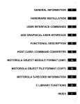
Customer Service and Support
Customer support is available 9:00 am to 4:30 pm, Eastern Standard Time, Monday
through Friday. Please have the model, serial number and a detailed problem description available. If the problem concerns a particular reading, please have all meter
readings available. When returning any merchandise to EIG, a return materials
authorization number is required. For customer or technical assistance, repair or
calibration, phone 516-334-0870 or fax 516-338-4741.
Product Warranty
Electro Industries/GaugeTech warrants all products to be free from defects in material
and workmanship for a period of four years from the date of shipment. During the
warranty period, we will, at our option, either repair or replace any product that
proves to be defective.
To exercise this warranty, fax or call our customer-support department. You will
receive prompt assistance and return instructions. Send the instrument, transportation prepaid, to EIG at 1800 Shames Drive, Westbury, NY 11590. Repairs will be made
and the instrument will be returned.
This warranty does not apply to defects resulting from unauthorized modification,
misuse, or use for any reason other than electrical power monitoring. The MP200TM in
Enclosure is not a user-serviceable product.
THIS WARRANTY IS IN LIEU OF ALL OTHER WARRANTIES, EXPRESSED
OR IMPLIED, INCLUDING ANY IMPLIED WARRANTY OF MERCHANTABILITY OR FITNESS FOR A PARTICULAR PURPOSE. ELECTRO INDUSTRIES/
GAUGETECH SHALL NOT BE LIABLE FOR ANY INDIRECT, SPECIAL OR
CONSEQUENTIAL DAMAGES ARISING FROM ANY AUTHORIZED OR
UNAUTHORIZED USE OF ANY ELECTRO INDUSTRIES/GAUGETECH
PRODUCT. LIABILITY SHALL BE LIMITED TO THE ORIGINAL COST OF
THE PRODUCT SOLD.
Electro Industries/GaugeTech
Electro Industries/GaugeTech
The Leader In Power Monitoring and Smart Grid Solutions
The Leader In Power Monitoring and Smart Grid Solutions
Doc#
E180701
ii
Use of Product for Protection
OUR PRODUCTS ARE NOT TO BE USED FOR PRIMARY OVER-CURRENT PROTECTION.
ANY PROTECTION FEATURE IN OUR PRODUCTS IS TO BE USED FOR ALARM OR
SECONDARY PROTECTION ONLY.
Statement of Calibration
Our instruments are inspected and tested in accordance with specifications published
by Electro Industries/GaugeTech. The accuracy and a calibration of our instruments
are traceable to the National Institute of Standards and Technology through
equipment that is calibrated at planned intervals by comparison to certified standards.
For optimal performance, EIG recommends that any metering device, including those
manufactured by EIG, be verified for accuracy on a yearly interval using NIST traceable accuracy standards.
Disclaimer
The information presented in this publication has been carefully checked for reliability; however, no responsibility is assumed for inaccuracies. The information contained
in this document is subject to change without notice.
Symbols Used in This Manual
This warning symbol indicates that the operator must refer to an
important explanation in the operating instructions. The word following the symbol indicates the type of warning being given.
Ce symbole d'avertissement indique que l'opérateur doit se référer à
une explication importante dans les instructions d'utilisation. Le mot suivant le symbole
indique le type d'avertissement ne soit donné.
CAUTION!
The instructions given must be followed to prevent damage to
equipment.
Les instructions doivent être respectées pour éviter
d'endommager l’équipement.
WARNING!
The instructions given must be followed to prevent serious
injury to people.
Les instructions doivent être respectées pour d’éviter de graves
blessures aux personnes.
Electro Industries/GaugeTech
Electro Industries/GaugeTech
The Leader In Power Monitoring and Smart Grid Solutions
The Leader In Power Monitoring and Smart Grid Solutions
Doc#
E180701
iii
This page intentionally left blank.
Electro Industries/GaugeTech
Electro Industries/GaugeTech
The Leader In Power Monitoring and Smart Grid Solutions
The Leader In Power Monitoring and Smart Grid Solutions
Doc#
E180701
iv
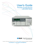
Table of Contents
Table of Contents
Customer Service and Support
ii
Product Warranty
ii
Use of Product for Protection
iii
Statement of Calibration
iii
Disclaimer
iii
Symbols Used in This Manual
iii
1: Introduction
1-1
1.1: Product Handling
1-1
1.2: Safety Precautions
1-2
1.3: Storage
1-3
1.4: Compliance
1-3
2: Installation
2-1
2.1: Installation Step 1 - Unpack the Enclosure
2-2
2.2: Installation Step 2 - Drill the Wiring Holes
2-4
2.2.1: Removing and Reinstalling the Panel
2-7
2.3: Installation Step 3 - Mount the Enclosure
2-9
2.4: Installation Step 4 - Install the Display
2-14
2.5: Installation Step 5 - Lock the Enclosure
2-18
3. Electrical Wiring
3-1
3.1: Wiring Instructions
3-2
4: Operation
4-1
4.1: Overview
4-1
Electro Industries/GaugeTech
Electro Industries/GaugeTech
The Leader In Power Monitoring and Smart Grid Solutions
The Leader In Power Monitoring and Smart Grid Solutions
Doc#
E180701
TOC-1
Table of Contents
4.2: Troubleshooting
4-1
5. Maintenance
5-1
5.1: Removing a Meter From Service
5-1
5.2: Reinstalling the Meter
5-6
6. Ordering Information
6-1
Electro Industries/GaugeTech
Electro Industries/GaugeTech
The Leader In Power Monitoring and Smart Grid Solutions
The Leader In Power Monitoring and Smart Grid Solutions
Doc#
E180701
TOC-2
1:Introduction
1: Introduction
The MP200TM in Enclosure lets you expand your switchgear capability and/or easily
meter circuits without expensive and time-consuming redesign. Simply mount the
enclosure in any convenient location, next to your switchgear or on a wall, and you are
ready to go, with no downtime.
This is an ideal solution for a retrofit when there is no metering compartment available. The unit comes standard with a NEMA 1 rated enclosure and is factory wired with
the metering system installed. Standard safety equipment includes voltage fuses and
shorting blocks for current transformers.
The enclosure can be ordered with either the MP200-Y three phase circuit configuration or the MP200-S single phase circuit configuration, and comes standard with
either a 3”x5” or 5”x7” touch-screen display. BACnet® or LonWorks® protocol is
available as an add-on to the existing standard Modbus® capability. See Chapter 6 for
ordering instructions.
1.1: Product Handling
CAUTION! READ AND UNDERSTAND THE INSTRUCTIONS CONTAINED IN
THIS DOCUMENT BEFORE ATTEMPTING TO UNPACK, INSTALL, OPERATE,
OR MAINTAIN THIS EQUIPMENT.
Every effort is made to insure that the equipment arrives undamaged and ready to be
installed. Packing is designed to protect internal components as well as the enclosure.
Do not remove protective packing until you are ready to install the equipment.
When you receive the equipment, you should inspect the shipping container for any
obvious signs of rough handling and/or external damage that occurred during transportation. Record any external and internal damage for reporting to the transportation
carrier and EIG. All claims should be as specific as possible and include general order
numbers.
You will find a plastic bag of instruction booklets and/or CDs in the shipping container.
Store these documents in a safe place.
Electro Industries/GaugeTech
Electro Industries/GaugeTech
The Leader In Power Monitoring and Smart Grid Solutions
The Leader In Power Monitoring and Smart Grid Solutions
Doc#
E180701
1-1
1:Introduction
1.2: Safety Precautions
WARNING! All safety codes, safety standards, and/or regulations must be strictly observed in the installation, operation,
and maintenance of this device.
Hazardous voltages that can cause death or severe personal injury are present inside
enclosure. Follow proper installation, operation, and maintenance procedures to avoid
these voltages.
Avertissement! tous les codes de sécurité, normes de sécurité et règlements
doivent être suivis strictement dans l'installation, le fonctionnement et la
maintenance de cet appareil.
Des tensions dangereuses peuvent provoquer la mort ou des blessures graves. suivre
l'installation adéquate, le fonctionnement et les procédures de maintenance pour
éviter ces tensions.
Completely read and understand the material presented in this document before
attempting installation, operation, or application of the equipment. In addition, only
qualified persons should be permitted to perform any work associated with the
equipment. Any wiring instructions presented in this document must be followed
precisely. Failure to do so could cause permanent equipment damage.
All possible contingencies that may arise during installation, operation, or maintenance, and all details and variations of this equipment do not purport to be covered by
these instructions. If further information is desired by purchaser regarding a particular
installation, operation, or maintenance of particular equipment, contact an Electro
Industries/GaugeTech (EIG) representative.
Electro Industries/GaugeTech
Electro Industries/GaugeTech
The Leader In Power Monitoring and Smart Grid Solutions
The Leader In Power Monitoring and Smart Grid Solutions
Doc#
E180701
1-2
1:Introduction
1.3: Storage
Although it has been well packaged, this equipment should not be stored outdoors. If
the equipment is to be stored indoors for any period of time, it should be stored with
its protective packaging in place. Refer to the MP200TM Metering System Installation
and Operation manual, on the enclosed CD, for the meter’s storage requirements.
The temperature rating for enclosure storage is (-20 to +50)o C.
1.4: Compliance
UL / cUL Listed, UL508A, File number: E358101.
Electro Industries/GaugeTech
Electro Industries/GaugeTech
The Leader In Power Monitoring and Smart Grid Solutions
The Leader In Power Monitoring and Smart Grid Solutions
Doc#
E180701
1-3
1:Introduction
This page intentionally left blank.
Electro Industries/GaugeTech
Electro Industries/GaugeTech
The Leader In Power Monitoring and Smart Grid Solutions
The Leader In Power Monitoring and Smart Grid Solutions
Doc#
E180701
1-4
2: Installation
2: Installation
WARNING! All safety codes, safety standards, and/or regulations shall be
strictly observed in the installation, operation, and maintenance of this
device. This device shall be installed in an un-energized condition
and as per the National Electric Code.
AVERTISSEMENT! Tous les codes de sécurité, normes de sécurité et règlement doivent être suivis strictement pour l'installation, le fonctionnement et la maintenance de
cet appareil. Cet appareil doit être installé hors tension conformément au code
électrique national (National Electric Code).
Choose a mounting location that offers a flat, rigid mounting surface capable of
supporting the weight of the equipment. The unit weighs 48.5 lbs (22 kg) maximum.
Mount the equipment in a suitable environment. This enclosures is designed for NEMA
1 rated environments and is manufactured of painted steel.
Check to make certain that there are no pipes, wires, or other mounting hazards in
the immediate mounting area that could create a problem. Also make sure you have
enough clearance around the enclosure to run wiring to it safely. EIG recommends at
least 2 feet of clearance around the enclosure. See Section 2.1 for enclosure dimensions.
Carefully remove all packing material from the unit. Even though an equipment
inspection was made when the equipment was received, make another careful inspection of the enclosure and the devices inside as packing material is removed. Be
especially alert for distorted metal, loose wires, or damaged components. This is
important because wiring can come loose in shipping and could cause a short circuit
or voltage to be on the wrong terminal.
WARNING! Extreme care shall be taken when mounting the enclosure, and
making wire entry holes, to prevent metal chips, filings, and other contaminants from entering the enclosure which may damage the equipment and
create a hazardous condition.
AVERTISSEMENT! Attention extrême lors de la monture de l'enceinte et lors de la
mise à terre pour prévenir les articules métalliques, remplissage et autre contaminant
de l'entrée de l'enceinte qui peuvent provoquer une condition dangereuse de l'équipement.
Electro Industries/GaugeTech
Electro Industries/GaugeTech
The Leader In Power Monitoring and Smart Grid Solutions
The Leader In Power Monitoring and Smart Grid Solutions
Doc#
E180701
2-1
2: Installation
2.1: Installation Step 1 - Unpack the MP200TM in Enclosure
The MP200TM in enclosure ships in two parts:
• The meter enclosure
• The mountable color display
The display is shipped separately in order to protect it from being damaged during
shipping.
Instructions for the enclosure begin on the next page. Section 2.4 contains
instructions for mounting the display.
Electro Industries/GaugeTech
Electro Industries/GaugeTech
The Leader In Power Monitoring and Smart Grid Solutions
The Leader In Power Monitoring and Smart Grid Solutions
Doc#
E180701
2-2
2: Installation
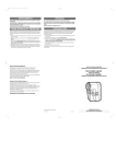
The enclosure components are shown in the image below:
• A: Current inputs (24 of them)
• B: CT shorting blocks (8 of them)
• C: Voltage inputs and 4 fuses
• D: Ground wire on back side of enclosure
• E: Ground wire on enclosure door
• F: Cable assembly
• G: Display connectors
• H: Hole for mounting the display
• I: If ordered, optional Add-on Protocol - ProtoCom/ProtoCom-Lon
G
B
I
H
A
F
E
D
C
Figure 2.1: MP200TM in Enclosure as Shipped
Electro Industries/GaugeTech
Electro Industries/GaugeTech
The Leader In Power Monitoring and Smart Grid Solutions
The Leader In Power Monitoring and Smart Grid Solutions
Doc#
E180701
2-3
2: Installation
2.2: Installation Step 2 - Drill the Wiring Holes
Cut the holes you need in the bottom of the enclosure for the power, CT, and
communications wiring. See the figure below for the allowable location.
95.25 mm
3.75 in
38.10 mm
1.50 in
HOLES
BOTTOM VIEW OF ENCLOSURE
You can cut holes
inside this area
1.00in[25.40mm]
1.50in[38.10mm]
3.75in
[95.25mm]
1.50in[38.10mm]
WALL
Figure 2.2: Location for Punch Entries
The drawings show the area in the bottom of the enclosure where wiring holes can be
cut: 1” [25.40mm] from the front of the enclosure, 1.5” [38.10mm] from the right
side of the enclosure, 1.5” [38.10mm] from the back of the enclosure, and 3.75”
[95.25mm] from the left side of the enclosure.
Electro Industries/GaugeTech
Electro Industries/GaugeTech
The Leader In Power Monitoring and Smart Grid Solutions
The Leader In Power Monitoring and Smart Grid Solutions
Doc#
E180701
2-4
2: Installation
CAUTIONS!
• There are numerous methods for making wire entry holes in the enclosure but it
is imperative that no loose material generated during the process remains in the
enclosure. During installation and cutting the wire holes, all equipment mounted
inside or on the enclosure shall be protected from loose material.
•
No matter what procedure is used the installer shall verify that the hole cutting
process will not damage any of the wiring or components installed inside or on
the enclosure.
a. The two recommended procedures for cutting the wire entry holes are as
follows:
• Use a "C" frame punch to cut the wire entry holes. This type of punch
does not require a pilot hole. A typical "C" frame punch is shown below.
Figure 2.3: “C” Frame Punch
• Regular punch:
1. Place a magnet inside the enclosure where the pilot hole is to be cut
and completely cover the area with masking tape (or other very
sticky tape).
2. Drill the pilot hole from the outside and do not let the drill pass more
than ¼" into the enclosure.
3. Remove the tape, magnet, and cuttings and punch the hole.
Electro Industries/GaugeTech
Electro Industries/GaugeTech
The Leader In Power Monitoring and Smart Grid Solutions
The Leader In Power Monitoring and Smart Grid Solutions
Doc#
E180701
2-5
2: Installation
b. After wiring and before energizing, vacuum the inside of the enclosure to
make sure that it is free of foreign material. If a vacuum is not available
use an alternate method to clean the inside of the enclosure. Do not use
compressed air (or pressurized gas) to clean the inside of the enclosure as
this may force cuttings into areas that cannot be seen, creating a hazardous condition.
IMPORTANT! All wire entry into the enclosure shall be accomplished with
the use of recognized fittings or strain reliefs. Bare holes shall not be
used.
NOTE: the panel can be removed to facilitate drilling of wiring holes. See the following procedure.
Electro Industries/GaugeTech
Electro Industries/GaugeTech
The Leader In Power Monitoring and Smart Grid Solutions
The Leader In Power Monitoring and Smart Grid Solutions
Doc#
E180701
2-6
2: Installation
2.2.1: Removing and Reinstalling the Panel
If it will make it easier to drill the wiring holes, you may remove the panel.
K
I
F
J
E
D
Figure 2.4: Removing the Panel
1. If the MP200TM in enclosure is equipped with a ProtoCom/ProtoCom-Lon add-on
protocol unit remove all connections from the ProtoCom/ProtoCom-Lon (I).
2. Disconnect the green ground wires from the door (E).
3. Open the cable clamps on the door (J) and remove the cable assembly (F).
4. Remove the green ground wires on the lower left side of the enclosure (D).
5. Remove the four nuts, one in each corner of the panel [K].
6. Carefully remove the panel from the enclosure.
Drill the wiring holes per the instructions in Section 2.2. You can then re-install the
panel.
1. Place the panel on the four mounting studs in the enclosure and install and tighten
a nut on each of the studs (K).
Electro Industries/GaugeTech
Electro Industries/GaugeTech
The Leader In Power Monitoring and Smart Grid Solutions
The Leader In Power Monitoring and Smart Grid Solutions
Doc#
E180701
2-7
2: Installation
2. Connect the green ground wires to the ground stud on the bottom left of the
enclosure (D).
3. Insert the cable assembly (F) into the cable clamps on the door (J).
4. Connect the two green ground wires to the stud on the door (E).
5. If the MP200TM in enclosure is equipped with a ProtoCom/ProtoCom-Lon, attach
all connections to it (I).
Continue to Section 2.3 to mount the enclosure.
Electro Industries/GaugeTech
Electro Industries/GaugeTech
The Leader In Power Monitoring and Smart Grid Solutions
The Leader In Power Monitoring and Smart Grid Solutions
Doc#
E180701
2-8
2: Installation
2.3: Installation Step 3 - Mount the Enclosure
1. Determine the enclosure mounting location - where there are no obstacles and the
exterior wiring can be easily accomplished. Install as per the NEC or local code
requirements. Refer to the following diagrams for the enclosure dimensions.
516.19 mm
20.32 in
517.91 mm
20.39 in
Figure 2.5: Enclosure Front Dimensions
Electro Industries/GaugeTech
Electro Industries/GaugeTech
The Leader In Power Monitoring and Smart Grid Solutions
The Leader In Power Monitoring and Smart Grid Solutions
Doc#
E180701
2-9
2: Installation
185.67 mm
7.31 in
166.31 mm
6.54 in
508.00 mm
20.00 in
Figure 2.6: Enclosure Side Dimensions
Electro Industries/GaugeTech
Electro Industries/GaugeTech
The Leader In Power Monitoring and Smart Grid Solutions
The Leader In Power Monitoring and Smart Grid Solutions
Doc#
E180701
2-10
2: Installation
508.00 mm
20.00 in
Figure 2.7: Enclosure Top Dimensions
Electro Industries/GaugeTech
Electro Industries/GaugeTech
The Leader In Power Monitoring and Smart Grid Solutions
The Leader In Power Monitoring and Smart Grid Solutions
Doc#
E180701
2-11
2: Installation
2. Mark the location of the four mounting points on the surface where the enclosure
will reside.
723
PP
LQ PP
LQ PP
LQ PP
LQ PP
LQ P
P
LQ
P
P
LQ
8SSHUPRXQWLQJKROHV
PP
LQ P
P LQ
/RZHUPRXQWLQJKROHV
PP
L
Q
PP
LQ PP
LQ PP
LQ PP
LQ PP
LQ PP
LQ Figure 2.8: Mounting Hole Locations and Dimensions
3. Prepare the mounting points using attachment means appropriate for the surface
supporting the enclosure.
4. Put two fasteners (screws or bolts) in the top two mounting locations, the
fasteners shall have a head diameter of no greater than 0.65" and a maximum
body diameter of 0.25".
5. Install upper mounting screws; leave a 3/8" gap between the screw head and the
mounting surface.
6. Lift the enclosure and hang it from the top two bolts.
Electro Industries/GaugeTech
Electro Industries/GaugeTech
The Leader In Power Monitoring and Smart Grid Solutions
The Leader In Power Monitoring and Smart Grid Solutions
Doc#
E180701
2-12
2: Installation
7. Install lower mounting screws from the inside of the cabinet. Loosely tighten.
8.If necessary shim between the mounting surface and the enclosure to compensate
for any irregularities.
9.Tighten the lower two fasteners.
Bend label upward to
access the two top
mounting screws
Bottom mounting screws
Figure 2.9: Location of Mounting Screws
10. Fold back the CT wiring labels in the upper right and left corners of the enclosure
(see figure above) and tighten the upper two mounting fasteners.
Electro Industries/GaugeTech
Electro Industries/GaugeTech
The Leader In Power Monitoring and Smart Grid Solutions
The Leader In Power Monitoring and Smart Grid Solutions
Doc#
E180701
2-13
2: Installation
2.4: Installation Step 4 - Install the Display
The display ships separately from the enclosure. The contents of the display box are
shown below.
1
2
4
3
6
5
7
Figure 10.10: Display Kit Contents
(1) Display
(2) Rear Module
(3) Power Supply*
(4) RS485 Serial Cable (10 feet)*
Mounting Hardware:
(5) anti-rotation tee
(6) socket wrench
(7) installation nut, attached to the back of the display
*These items are included in the display box, but are only needed if you want to
mount the display remotely, rather than in the enclosure. If you are mounting
remotely, cover up the display mounting hole that is in the enclosure cover.
Follow the instructions beginning on the next page to mount the display in the
enclosure front cover.
Electro Industries/GaugeTech
Electro Industries/GaugeTech
The Leader In Power Monitoring and Smart Grid Solutions
The Leader In Power Monitoring and Smart Grid Solutions
Doc#
E180701
2-14
2: Installation
1.There are 5 parts to the display as installed in the MP200TM in enclosure:
(1)
(8)
(2)
(5)
(7)
Figure 2.11: Display Components for Mounting in Enclosure
• Display module and touch screen (1)
• Panel with cutout (8)
• Display installation nut (7)
• Anti-rotation Tee (5)
• Rear module, containing the electronics to run the display (2)
Electro Industries/GaugeTech
Electro Industries/GaugeTech
The Leader In Power Monitoring and Smart Grid Solutions
The Leader In Power Monitoring and Smart Grid Solutions
Doc#
E180701
2-15
2: Installation
2. Press the Anti-rotation tee (5) into the display module (1), in the hole provided [9].
1
9
5
10
7
6
Figure 2.12: Inserting the Display into the Panel
3. Insert the display module, with the anti-rotation Tee attached, into the cutout,
aligning the anti-rotation tee so that it passes through the small hole in the panel
(10).
4. Place the display installation nut on the portion of the display passing through the
panel and “finger tighten” it.
5. Using the socket wrench supplied [6], tighten the display installation nut (7) with a
torque between 1.2 and 1 Nm (10.6 to 17.7 in-lb).
Electro Industries/GaugeTech
Electro Industries/GaugeTech
The Leader In Power Monitoring and Smart Grid Solutions
The Leader In Power Monitoring and Smart Grid Solutions
Doc#
E180701
2-16
2: Installation
Top of panel
Yellow button
2
2
1
Insert and
push
Free
Locked
Figure 2.13: Connecting the Rear Module to the Display Module
6. Carefully insert the rear module (2), with the yellow button to the top of the
enclosure, and push the rear module until it locks into place. When it is in place
you will hear a "click.”
7. Connect the cable to the rear module: see Figure 2-1.
Electro Industries/GaugeTech
Electro Industries/GaugeTech
The Leader In Power Monitoring and Smart Grid Solutions
The Leader In Power Monitoring and Smart Grid Solutions
Doc#
E180701
2-17
2: Installation
2.5: Installation Step 5 - Lock the Enclosure
The enclosure has been fitted with means for securing the door so it cannot be
opened or tampered with. A key lock is provided along with two keys.
Enclosure
Lock
Figure 2.14: Location of Enclosure Lock
1. Lock the enclosure by putting the key in the lock and turning it clockwise.
2. Remove the key and store it in a safe place. When you want to open the enclosure,
put the key in the lock and turn it counter-clockwise. Repeat step 1 to re-lock the
enclosure.
Electro Industries/GaugeTech
Electro Industries/GaugeTech
The Leader In Power Monitoring and Smart Grid Solutions
The Leader In Power Monitoring and Smart Grid Solutions
Doc#
E180701
2-18
3: Electrical Wiring
3. Electrical Wiring
The MP200TM in Enclosure is factory wired and tested. Installation requires solidly
mounting the enclosed unit and connecting field wiring. This document has diagrams
of wiring options. Review and understand the appropriate diagrams for the unit you
have ordered.
NOTE: See the diagram below for input wiring specifications. Consult your local and/
or National Electric Code for external wiring requirements.
Both enclosure models are pre-wired and programmed for either three phase or single
phase operation.
NOTE: The current inputs are only to be connected to external current transformers
provided by the installer. The CT's shall be Listed to ANSI/IEEE C57.13 and rated for
the current of the meter used.
A DISCONNECTING MEANS AND UPSTREAM PROTECTION SHOULD BE INSTALLED
FOR ALL CIRCUITS. A SHORT-CIRCUIT–TYPE TERMINAL BLOCK IS PROVIDED FOR
THE CURRENT TRANSFORMER CIRCUIT.
INPUT WIRING SPECIFICATIONS
Location
Wire Size
Screw Size
Maximum Torque
Shorting Block
#6-22 AWG CU
#10-32
20 lbf-in (2.3 N-m)
Fuse Block
#10-18 AWG CU
#10-32
20 lbf-in (2.3 N-m)
#8-32
6 lbf-in (0.68 N-m)
#8-32
10 lbf-in (1.2 N-m)
Neutral Wire
Earth Ground
#12 max CU
#10-12 AWG CU
Electro Industries/GaugeTech
Electro Industries/GaugeTech
The Leader In Power Monitoring and Smart Grid Solutions
The Leader In Power Monitoring and Smart Grid Solutions
Doc#
E180701
3-1
3: Electrical Wiring
3.1: Wiring Instructions
WARNING!
First connect Earth Ground as shown in the figure below.
AVERTISSEMENT! Branchez d'abord la mise à la terre comme indiqué
dans le dessin ci-dessous.
Earth Ground
Figure 3.1: Earth Ground Connection
Electro Industries/GaugeTech
Electro Industries/GaugeTech
The Leader In Power Monitoring and Smart Grid Solutions
The Leader In Power Monitoring and Smart Grid Solutions
Doc#
E180701
3-2
3: Electrical Wiring
Understand the diagram(s) that pertain to your unit before you begin the field
wiring. The following figures show the available wiring options. Understand your system and use the appropriate figures.
WARNING! CONTROL WIRING MAY HAVE VOLTAGE PRESENT THAT CAN
CAUSE SEVERE PERSONAL INJURY OR DEATH. DE-ENERGIZE ALL
CONDUCTORS BEFORE BEGINNING TO PERFORM ANY WIRING ACTIVITY
TO OR WITHIN THE MP200TM IN ENCLOSURE.
AVETISSEMENT! LE CÂBLAGE DES COMMANDES PEUT AVOIR UNE TENSION
PRÉSENTE QUI PEUT PROVOQUER DES BLESSURES GRAVES POU LA MORT. METTRE
HORS TENSION TOUS LES CONDUCTEURS AVANT DE COMMENCER LA RÉALISATION
D'UNE ACTIVITÉ DE CÂBLAGE DANS L'ENCEINTE DE L'ASSEMBLAGE MP200TM.
Electro Industries/GaugeTech
Electro Industries/GaugeTech
The Leader In Power Monitoring and Smart Grid Solutions
The Leader In Power Monitoring and Smart Grid Solutions
Doc#
E180701
3-3
3: Electrical Wiring
/,1(
9 9
&76+257,1*%/2&.
9
U
1
U
U
:+,7(
&855(17$+,
%/$&.
&855(17$/2
:+,7(
&855(17%+,
%/$&.
&855(17%/2
:+,7(
&855(17&+,
%/$&.
&855(17&/2
U
7203&855(17,13876
U
U
21/<21(3+$6(&,5&8,7,66+2:1
'83/,&$7(,7)25$'',7,21$/&,5&8,76
U
*1'
)86(%/2&.
81,732:(5/
/
U
9
92/7$*($
720392/7$*(32:(5,13876
U
U
U
9
92/7$*(%
9
92/7$*(&
1
1(875$/
/2$'
Figure 3.2: MP200-Y Three Phase Wiring Diagram
Electro Industries/GaugeTech
Electro Industries/GaugeTech
The Leader In Power Monitoring and Smart Grid Solutions
The Leader In Power Monitoring and Smart Grid Solutions
Doc#
E180701
3-4
3: Electrical Wiring
/,1(
9
9
U
&76+257,1*%/2&.
1
U
:+,7(
&855(17+,
%/$&.
&855(17/2
:+,7(
&855(17+,
%/$&.
&855(17/2
U
7203&855(17,13876
U
U
21/<21(&,5&8,7,66+2:1
'83/,&$7()25$'',7,21$/&,5&8,76
U
*1'
)86(%/2&.
81,732:(5/
/
U
9
92/7$*($
720392/7$*(32:(5,13876
U
9
92/7$*(%
92/7$*(&
U
1
U
1(875$/
/2$'
Figure 3.3: MP200-S Single Phase Wiring Diagram
Electro Industries/GaugeTech
Electro Industries/GaugeTech
The Leader In Power Monitoring and Smart Grid Solutions
The Leader In Power Monitoring and Smart Grid Solutions
Doc#
E180701
3-5
3: Electrical Wiring
This page intentionally left blank.
Electro Industries/GaugeTech
Electro Industries/GaugeTech
The Leader In Power Monitoring and Smart Grid Solutions
The Leader In Power Monitoring and Smart Grid Solutions
Doc#
E180701
3-6
4: Operation
4: Operation
4.1: Overview
The MP200TM in Enclosure is equipped with three 10mm x 38mm, 600V, 100mA, fastacting fuses and one 10mm x 38mm, 500V, 3A, Time Delay fuse for the protection of
the meter’s sense voltage and control power circuits, respectively.
A disconnecting means and upstream protection should be installed for all circuits.
Short-circuit type terminal blocks are provided for the current transformer circuit. The
terminal blocks for the current circuits are short-circuit type and are equipped with
captive shorting screws (see instructions in Section 5.1).
The temperature rating for enclosure operation is (-20 to +50)o C.
Refer to the MP200TM Metering System Installation and Operation Manual for specific
operating instructions for the system in your enclosure.
4.2: Troubleshooting
Symptom: Extremely inaccurate readings of voltage and/or harmonics.
Perform these two tests:
1. With fuses removed from the unit, test the fuses with an ohmmeter. All of the fuses
must show a resistance of <2 Ohms.
2. With the unit fully powered, measure the voltage on the input side and output side
of the fuse. The voltages should differ by less than 1 Volt.
Electro Industries/GaugeTech
Electro Industries/GaugeTech
The Leader In Power Monitoring and Smart Grid Solutions
The Leader In Power Monitoring and Smart Grid Solutions
Doc#
E180701
4-1
4: Operation
This page intentionally left blank.
Electro Industries/GaugeTech
Electro Industries/GaugeTech
The Leader In Power Monitoring and Smart Grid Solutions
The Leader In Power Monitoring and Smart Grid Solutions
Doc#
E180701
4-2
5: Maintenance
5. Maintenance
The MP200TM in Enclosure is designed to be relatively maintenance-free under normal
use. However, because of the variability of application conditions and the importance
placed on dependable operation and inspection, you should perform maintenance
checks on a regularly scheduled basis. Visually inspect for loose parts, wires, and/or
hardware; inspect for discoloration of insulation and damaged or discolored components; be alert for accumulation of dirt and/or moisture on structure; check operation
of disconnecting means and continuity of fuses, where applicable.
5.1: Removing a Meter From Service
Follow these steps:
1. De-energize all circuits feeding the case.
2. If possible de-energize lines that the CTs are on.
3. Tighten all the shorting screws on all the CT shorting blocks by turning all the
screws clockwise until they bottom out.
WARNING! If the meter must be removed from service, the
secondary side of the current transformers MUST be short circuited to
prevent a dangerous high voltage condition from appearing across the
secondary wires of the current transformer. Arcing and damage to personnel and/
or equipment can occur if the screws provided on the shorting block are not
installed in the correct locations, prior to disconnecting any wires.
AVERTISSEMENT! Si le compteur doit être enlevé du service, le côté secondaire du
transformateur actuel DOIT être court-circuité pour prévenir une condition de haute
tension dangereuse d'apparaitre dans les câblages secondaires du transformateur
actuel. La brulure d'arc et l'endommagement d'un équipement ou des blessures sont
susceptibles de se produire si les vis fournies sur le court-circuit ne sont pas installées
dans les emplacements corrects avant de débrancher les câbles.
The six screws on each shorting block are used to short the high (+) sides and the
low (-) side of the CT outputs to the brass bar that is internal to the shorting block.
The pre-installed jumper connects all lows together and to ground.
Electro Industries/GaugeTech
Electro Industries/GaugeTech
The Leader In Power Monitoring and Smart Grid Solutions
The Leader In Power Monitoring and Smart Grid Solutions
Doc#
E180701
5-1
5: Maintenance
WARNING! The screws need to be screwed down until the screw makes
contact with the internal bar, enabling the bar to become electrically
common with the terminal strip, and grounded.
Les vis doivent être vissées jusqu'à ce que la vis soit en contact avec la barre
interne, permettant à la barre de devenir électriquement commune à la barrette de raccordement et mise à la terre.
The figure below shows where the screws are located that must be tightened down to
short the CTs.
Figure 5.1: CT/Shorting Block Location
Electro Industries/GaugeTech
Electro Industries/GaugeTech
The Leader In Power Monitoring and Smart Grid Solutions
The Leader In Power Monitoring and Smart Grid Solutions
Doc#
E180701
5-2
5: Maintenance
TURN SCREWS CLOCKWISE
TO SHORT THE CT
5.2: Shorting the CT
WARNING! When you re-install the meter, make sure all CT connections are
made BEFORE unscrewing the shorting screws. See Section 5.2.
AVERTISSEMENT! Lorsque vous réinstallez le compteur, assurez-vous que
toutes les connexions de TC (transformateur de courant) sont faites AVANT de dévisser les
vis de court-circuit. Voir la section 5.2.
Electro Industries/GaugeTech
Electro Industries/GaugeTech
The Leader In Power Monitoring and Smart Grid Solutions
The Leader In Power Monitoring and Smart Grid Solutions
Doc#
E180701
5-3
5: Maintenance
MP 200 MOUNTING SCREWS 4 LOCATIONS
{
{
{
{
{
{
{
{
CURRENT INPUT
METER 1
CURRENT INPUT
METER 2
CURRENT INPUT
METER 3
CURRENT INPUT
METER 4
GND
CONNECTION
POWER AND
VOLTAGE
CONNECTION
FUSE BANK
X4 FUSES
CURRENT INPUT
METER 5
CURRENT INPUT
METER 6
CURRENT INPUT
METER 7
CURRENT INPUT
METER 8
NEUTRAL
CONNECTION
Figure 5.3: MP200-Y in Enclosure Location of Fuses, Current Leads, Connectors, Mounting Screws
Electro Industries/GaugeTech
Electro Industries/GaugeTech
The Leader In Power Monitoring and Smart Grid Solutions
The Leader In Power Monitoring and Smart Grid Solutions
Doc#
E180701
5-4
5: Maintenance
MP 200 MOUNTING SCREWS 4 LOCATIONS
{
{
{
{
{
{
{
{
CURRENT INPUT
1-3
CURRENT INPUT
4-6
CURRENT INPUT
7-9
CURRENT INPUT
10 - 12
GND
CONNECTION
POWER AND
VOLTAGE
CONNECTION
FUSE BANK
X4 FUSES
CURRENT INPUT
13 - 15
CURRENT INPUT
16 - 18
CURRENT INPUT
19 - 21
CURRENT INPUT
22 - 24
NEUTRAL
CONNECTION
Figure 5.4: MP200-S in Enclosure Location of Fuses, Current Leads, Connectors, Mounting Screws
4. Remove the 4 fuses from the fuse block.
5. Un-screw and disconnect the 48 current leads to the meter.
6. Disconnect all connectors to the meter.
7. Remove the 4 mounting screws securing the MP200TM to the panel.
8. Remove the meter.
Electro Industries/GaugeTech
Electro Industries/GaugeTech
The Leader In Power Monitoring and Smart Grid Solutions
The Leader In Power Monitoring and Smart Grid Solutions
Doc#
E180701
5-5
5: Maintenance
5.2: Reinstalling the Meter
Follow this procedure to reinstall the meter:
1. Place meter in its location on the panel.
2. Tighten the 4 mounting screws.
3. Insert all connectors into the appropriate sockets on the meter.
4. Connect the 48 current leads to the meter making sure they are attached in the
proper order.
5. Install the 4 fuses in the fuse block in their proper location.
6. Unscrew all shorting screws on the CT connection block. See the figure below.
TURN SCREWS COUNTERCLOCKWISE TO OPEN THE CT
Figure 5.2: Opening the CTs
7. Verify that no foreign material remains inside the enclosure: clean it out if found.
8. Energize all circuits and verify operation.
Electro Industries/GaugeTech
Electro Industries/GaugeTech
The Leader In Power Monitoring and Smart Grid Solutions
The Leader In Power Monitoring and Smart Grid Solutions
Doc#
E180701
5-6
6: Ordering Information
6. Ordering Information
ENCMP200 - Y - 60 - 10 - V2 - 485P - MDSN - ProtoCom
1
2
3
4
5
6
7
8
1. Model:
ENCMP200 - MP200TM Metering System in NEMA 1 Enclosure
2. Circuit Configuration
Y - Three Phase WYE
S - Single Phase Only
3. Frequency
50 - 50Hz
60 - 60Hz
4. Current Class
10 - 10 Amp Secondary
2 - 2 Amp Secondary
5. V-Switch™ Key Pack
V1 - Transducer
V2 - Basic Logger
V3 - Advanced Logger
6. Communication
X - RS485 Only (Modbus)
WIFI - Ethernet and WiFi (Modbus)
7. Display
MDSN - 3.5" Touch Screen HMI Display with installation kit
MDLN - 5.7" Touch Screen HMI Display with installation kit
(Display Installation Kit includes: Display and Rear Module, RS485 Serial cable,
Power Supply, Mounting Hardware)
8. Add-on Protocol
X - No Add-on Protocol
ProtoCom - BACnet Protocol
ProtoCom-Lon - LonWorks Protocol
Electro Industries/GaugeTech
Electro Industries/GaugeTech
The Leader In Power Monitoring and Smart Grid Solutions
The Leader In Power Monitoring and Smart Grid Solutions
Doc#
E180701
6-1
6: Ordering Information
Example above:
ENCSMP200-Y-60-10-V2-X-MDSN-ProtoCom
(MP200-Y Metering System, with 60Hz frequency, Current Class 10, V-2 V-Switch™
key, RS485 only, MDSN 3.5” Touch Screen HMI Display, and ProtoCom converter)
Electro Industries/GaugeTech
Electro Industries/GaugeTech
The Leader In Power Monitoring and Smart Grid Solutions
The Leader In Power Monitoring and Smart Grid Solutions
Doc#
E180701
6-2