1
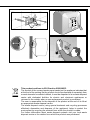
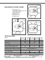
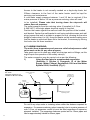
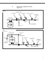
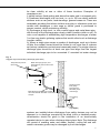
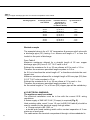
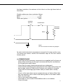
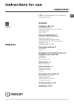
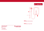
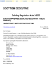
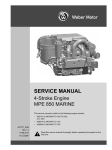
Unvented water heater
62
This product confirms to EU Directive 2002/96/EC.
The symbol of the crossed waste paper basket on the appliance indicates that
at the end of its working life the product should be disposed of separately from
normal domestic household rubbish, it must be disposed of at a waste disposal
centre with dedicated facilities for electric and electronic appliances or
returned to the retailer when a new replacement product is purchased.
The user is responsible for the disposal of the product at the end of its life at
an appropriate waste disposal centre.
The waste disposal centre (using special treatment and recycling processes
effectively dismantles and disposes of the appliance) helps to protect the
environment by recycling the material from which the product is made.
For further information about waste disposal systems visit your local waste
disposal centre or the retailer from which the product was purchased.
Description of water heater
1)Hot water outlet
2)Temperature and pressure relief
valve (30 litre only)
3)Cold water inlet
4)Control cover
5)Regulation knob
6)Heating neon
Over-sink (EP 10/15 OR)
Over-sink (EP 30 R 3KW)
Under-sink (EP 10/15 UR)
Technical data
MODEL
Approval
Capacity (litres)
Current (A)
Tension (V~)
Power (W)
Immersion Heater Length (mm)
Immersion Heater Type
Immersion Heater Refernce Number
Pressure max.
T & P valve setting
Weight with water
Moisture protection
EP 10 UR EP 15 UR EP 10 UR 3KW EP 15 UR 3KW EP 30 R
2 KW
2 KW
EP 10 OR 3KW EP 15 OR 3KW
3 KW
KIWA
KIWA
KIWA
10
15
10
15
30
8.7
13
13
220-240 V (50/60 Hz)
2000
3000
3000
160
160
185
Single Phase
BS 3456 Section 2.21
3.5 bar; 12 bar with pressure reducing valve
90°C/7bar
n/a
n/a
16 kg
45 kg
22 kg
18 kg
24 kg
DRIP PROOF IPX1
1
User instructions
PLEASE KEEP THIS BOOKLET FOR FUTURE REFERENCE
The heater is insulated to a high standard therefore it may be left on all the
time. The temperature of the water may be adjusted by turning the knob on
the front of the heater, allow half an hour for the temperature to stabilise
between settings. Maximum temperature is achieved with the knob turned
fully clockwise. The <<E>> mark on the regulation knob indicates an
<<economy>> setting and corresponds to a water temperature of 55 - 60°C.
In hard water areas we recommended a max. 60°C. The neon light shows
when the heating element is working, under control of the thermostat. If in
doubt ring Ariston Thermo UK Ltd. 0870 600 9888.
Note: The water heater does not have an “off” or “low” setting.
Water Regulations and Byelaws
These regulations and byelaws ensure a good supply of wholesome water,
and that only approved materials, pipes and fittings are used to convey
water.
Building Regulations
These are a statutory document and take priority over all other regulations
and recommendations. The installation of an unvented hot water system of
over 15 litres is classified as a “Controlled Service” and Regulation G3
applies. To meet the requirements of the regulation, installation of an
unvented system should be undertaken by a “competent installer”.
All installations of unvented hot water storage systems having a capacity of
more than 15 litres should be notified to the relevant Local Authority by
means of building notice or by the submission of full plans. It is important
to note that it is a criminal offence to install an unvented hot water storage
system over 15 litres without notifying the Local Authority.
Delivery
The EP models are supplied with the following:
EP unvented water heater (with factory-fitted T&P EP 30 R 3KW)
Wall bracket
Pressure relief valve set at 6 bar
Dielectric junctions
Tundish (model EP 30 R 3KW only)
2
x1
x1
x1
x2
x1
How the heater works
The heating element is controlled by a thermostat which senses the water
temperature. The operating temperature can be adjusted by the regulation
knob on the front of the heater.
In addition to the thermostat there is a thermal cut-out which is set to switch
off the power to the element if the thermostat fails and the water
temperature rises too high. Once the cut-out operates it can only be reset
manually (this should be carried out by the installer - see maintenance).
A magnesium anode is provided to prevent corrosion of the water
container. The EP 30 R 3KW model has a temperature and pressure relief
valve on top of the heater which is a safety device to back-up the
thermostat and thermal cut-out. It works by sensing an excess water
temperature or pressure and releasing the hot water to the discharge
tundish and drain.
The heater will only work in the vertical position as the element is shaped
to heat the water at the bottom of the tank. The inlet pipe needs to deliver
cold water to the bottom of the tank and the hot water outlet draws water
from the top of the tank.
When water is heated it expands, in a small unvented water heater of this
type the expansion can normally be accommodated back into the cold
water mains (not model EP 30 R 3KW).
Where this is not possible the installer will need to fit a set of cold water
controls.
Note: If a valve i.e. non-return valve on water meter or a pressure
limiting valve is installed on the cold water mains, this will prevent
expansion, therefore it will be necessary to install an expansion
vessel (see page 5, figs 2 & 3).
Installation instructions
Before installing the heater read these instructions in full. If you are
unsure please contact our technical service department (0870 600
9888).
The installation must comply with all relevant Water
Regulations/Byelaws and Building Regulations.
The installer should check with the local water authority for
confirmation of the maximum water supply pressure.
a) SITING & FIXING WARNING:
The appliance should be left packed until it is ready to be installed.
When unpacking the EP 30 R 3KW model take care not to damage the
temperature and pressure relief valve on the
top of the heater.
A drain has to be provided for any water discharged through the safety
valves.
3
Access to the heater is not normally needed on a day-to-day basis, but
300mm clearance to the front of the water heater sould be kept for
servicing and maintenance
A cold water supply pressure between 1 and 3.5 bar is required (if the
mains pressure is above 3.5 bar a pressure reducing valve will need
to be installed). Please note that turning down the stop-cock will
reduce flow not pressure.
The outlet pressure from the reducing valve (if supplied) is 3.5 bar.
A 240 VAC; 3 kW single phase electrical supply is required.
Position the heater against the wall and mark the position of the hooked
wall bracket. Fasten the wall bracket to wall using suitable screws and wall
plugs (ensure that wall is suitable to support the unit, allowing for the extra
weight of water when it is full). Hang the heater on the bracket making sure
that the heater is pulled well down on to the bracket, if necessary by forcing
the hooks into the foam insulation.
b) PLUMBING WARNING:
The outlet from temperature and pressure relief valve/pressure relief
valve must not be for any other purpose.
Take great care not to allow any swarf into the pipe work or fittings, as this
might impair the operation of the safety valve(s).
The water connection may be carried out as per the following:
1)
Using the feed pipe to accommodate expansion
(Schedule 2, Section 6: Paragraph 15 of the Water
Supply (Water Fittings) Regulations 1999 and the Water
Byelaws 2000, Scotland) (Fig. 1).
Fig. 1
EP 10/15
(Note this system is not
suitable for EP 30 R 3KW)
Hot
Pressure relief valve
(6 bar)
Dielectric
junctions
Nearest cold water
draw-off
Isolating valve
(fixed jumper or
1/4 turn ball type)
Cold
Cold
water
mains
Supply to other parts
of plumbing system
Discharge
2.8 m (10 l) or 4.2 m (15 l) of 15 mm pipe
is required for expansion
Do not fit any stop cocks or isolating valves within the distance required for
expansion. If a pressure reducing valve is needed, due to a mains pressure of
over 3.5 bar, an expansion control kit must be fitted regardless of expansion
pipework installed. The expansion distances quoted are for 15mm pipes and
can be approximately halved for 22mm pipes.
4
2)
Fig.. 2
EP 10/15
Using a set of expansion controls
(Fig. 2 & 3).
KIT A Expansion vessel
(charge at set 3.5 bar)
Nearest cold water
Pressure relief valve
draw-off
(6 bar)
KIT B Pressure reducing valve
(set at 3.5 bar)
Isolating valve
(fixed jumper or
1/4 turn ball type)
Dielectric junctions
(must be fitted)
Hot
Cold
Cold
water
mains
KIT A Non-return
valve
Supply to other parts
of plumbing system
Discharge
Fig. 3
EP 30 R 3KW
Pressure relief valve
(6 bar)
Temperature & pressure
relief valve (7 bar/90˚C)
Expansion vessel
(charge set at 3.5 bar)
Tundish
Nearest cold water
draw-off
Discharge to drain
Hot
Cold
Pressure reducing valve
(set at 3.5 bar)
Isolating valve
(fixed jumper or
1/4 turn ball type)
Dielectric
junctions
Cold
water
mains
Non-return
valve
Supply to other parts
of plumbing system
5
The EP 30 R 3KW is covered under the Building Regulations and therefore
it is not possible to accommodate the expansion water within the system
pipe work and consequently a set of expansion controls must be installed.
Note: The discharge from relief valves must be made in a safe and
conspicuous manner; therefore a tundish (Kit C) is available for 10 and 15
litre units if required.
Please note that in all cases the dielectric junctions must be
connected to the heater before any other connection is made (these
prevent an electrolytic reaction).
Only the use of copper pipe is recommended for connection to the
heater. If any other material is used it must be able to withstand 90°C
at 7 bar pressure for long periods.
No valve must be fitted between the expansion/pressure relief valve
and the water heater.
c) DISCHARGE PIPE WORK NOTE:
The following guidelines refer to Building Regulation G3. It is good
practice to follow these guidlines for all relief valve discharge pipe
work.
1) The tundish must be vertical and fitted within 600 mm of the temperature
& pressure relief valve and must be located with the cylinder. The tundish
must also be in a position visible to the occupants, and positioned away
from any electrical devices. The discharge pipe from the tundish should
terminate in a safe place where there is no risk to persons in the vicinity of
the discharge and to be of metal.
2) Discharge pipes from the temperature & pressure relief and pressure
relief valve may be joined together.
3) The pipe diameter must be at least one pipe size larger than the nominal
outlet size of the safety device unless it’s total equivalent hydraulic
resistance exceeds that of a straight pipe 9 m long.
i.e. Discharge pipes between 9 m and 18 m equivalent resistance length
should be at least 2 sizes larger than the nominal outlet size of the safety
device. Between 18 m and 27 m at least 3 times larger, and so on.
Bends must be taken into account in calculating the flow resistance.
See fig..5 and Table 2.
4) The discharge pipe must have a vertical section of pipe at least 300 mm
in length, below the tundish before any elbows or bends in the pipe work.
5) The discharge pipe must be installed with a continuous fall.
6) The discharge must be visible at both the tundish and the final point of
discharge, but where this is not possible or practically difficult; there should
6
be clear visibility at one or other of these locations. Examples of
acceptance are:
i) Ideally below a fixed grating and above the water seal in a trapped gully.
ii) Downward discharges at a low level; i.e. up to 100 mm above external
surfaces such as car parks, hard standings, grassed areas etc. These are
acceptable providing that where children may play or otherwise come into
contact with discharges, a wire cage or similar guard is positioned to
prevent contact, whilst maintaining visibility.
iii) Discharges at high level; i.e. into a metal hopper and metal down pipe
with the end of the discharge pipe clearly visible (tundish visible or not). Or
onto a roof capable of withstanding high temperature discharges of water
3 m from any plastic guttering systems that would collect such a discharge
(tundish visible).
iv) Where a single pipe serves a number of discharges, such as in blocks
of flats, the number served should be limited to not more than 6 systems
so that any installation can be traced reasonably easily. The single common
discharge pipe should be at least one pipe size large than the largest
individual discharge pipe to be connected. If unvented hot water storage
Fig.. 4
Suggest ways of terminating discharge pipes safely
Temperature & pressure
relief valve
Metal discharge pipe (D1) from
temperature & pressure relief valve.
to tundish.
Tundish
600 mm Max.
300 mm
Min.
Metal discharge pipe (D2) from tundish
with continuous fall. See Table 2 and worked
example.
Discharge below
fixed grating.
(see page 6 for
alternative points
of discharge).
Fixed grating
Trapped gulley
systems are installed where discharges from safety devices may not be
apparent i.e. in dwellings occupied by the blind, infirm or disabled people,
consideration should be given to the installation of an electronically
operated device to warn when discharge takes place. Note: The discharge
will consist of scalding water and steam. Asphalt, roofing felt and nonmetallic rainwater goods may be damaged by such discharges.
7
Table 2
Sizing of copper discharge pipe “D2” for common temperature valve outlets.
Valve outlet size
Minimum size of
discharge pipe D1*
Minimum size of
discharge pipe D2*
from tundish
Maximum
resistance allowed,
expressed as a
length of pipe (i.e.
no elbow or bends)
Resistance created
by each elbow or
bend
G 1/2
15 mm
G 3/4
22 mm
G1
28 mm
22 mm
28 mm
35 mm
28 mm
35 mm
42 mm
35 mm
42 mm
54 mm
Up to 9 m
Up to 18 m
Up to 27 m
Up to 9 m
Up to 18 m
Up to 27 m
Up to 9 m
Up to 18 m
Up to 27 m
0.8 m
1.0 m
1.4 m
1.0 m
1.4 m
1.7 m
1.4 m
1.7 m
2.3 m
Worked example
The example below is for a G 1/2” temperature & pressure relief valve with
a discharge pipe (D2) having 4 no. elbows and length of 7 m from the
tundish to the point of discharge.
From Table 2
Maximum resistance allowed for a straight length of 22 mm copper
discharge pipe (D2) from G 1/2” T & P valve is 9 m.
Subtract the resistance for 4 no. 22 mm elbows at 0.8 m each = 3.2 m.
Therefore the maximum permitted length equates to: 5.8 m.
As 5.8 m is less than the actual length of 7 m therefore calculate the next
largest size.
Maximum resistance allowed for a straight length of 28 mm pipe (D2) from
G 1/2” T & P valve equates to: 18 m.
Subtract the resistance for 4 no. 28 mm elbow at 1.0 m each = 4 m.
Therefore the maximum permitted length equates to: 14 m
As the actual length is 7 m, a 28 mm (D2) copper pipe will be satisfactory.
d) ELECTRICAL WARNING:
The appliance must be earthed
The electrical installation must be in line with the current I.E.E. wiring
regulations.
A mains supply of 240 VAC 3 kW (13 amps) is required (Fig. 5)
Heat resisting cable, round 3 core 1.5 mm (to BS 6141 table 8) should be
used to connect to the electrical supply through either:
- a 13 amp socket to BS 1363; or
- a double pole fused isolating switch with a contact separation of 3 mm
minimum on each pole.
The cable enters the terminal compartment through a tube embedded in
8
the foam insulation, the entrance to this tube is on the right hand side at
the bottom.
Flexible cables are colour coded as follows:
Brown.................................................. live
Blue............................................... neutral
Green and yellow............................. earth
THERMAL
CUT-OUT
THERMOSTAT
HEATING
ELEMENT
NEON
L
N
E
Fig..5
EP 10/15 and EP 30 R 3KW wiring diagram
To enter into the terminal compartment unscrew the 2 screws on the cover.
(To access the screws, remove the decorative caps on the front control
access panel).
e) COMMISSIONING
- Check that all the necessary components are supplied and for those not
factory fitted, that they are the type recommended by the manufacturer
for the particular water heater.
- Check that the water heater/components are undamaged.
- Check that the discharge pipe is plumbed so that it falls continuously and
that no taps, valves or other shut-off devices are installed in the pipe.
- Check that the discharge pipe drains safely to waste and is readily
visible.
- Check, in the case where some components are not factory fitted, that
they are marked so as to refer to the warning label on the water heater.
- Open all outlet taps.
- Turn on the mains water supply.
- Close taps in turn as water flow stabilises with no air bubbles.
- Check for leaks.
9
- Check that no water is passing through the safety valve(s).
- Test the operation of the safety valve(s) by lifting/turning the lever/knob,
and observing that water flows through and safely to waste.
- Switch on electricity and set thermostat to at 60°C to reduce the build up
of scale in hard water areas.
- Check the water heats up.
- Check that <<warning to user label>> is secure and visible on the heater
and related warning labels are fitted to the controls.
- Demonstrate operation to user, including operation of safety valve(s) and
what to do if it/they operate(s).
- Give this handbook to the user and discuss future maintenance.
Maintenance
a) For the user
In order to obtain the best performance from the heater, the sacrificial
anode must be checked every year and replaced as necessary. If the
heating element is heavily coated with scale we recommend descaling and
removing any lime deposit from the heater at the time of this inspection.
Where the additional cold water controls are fitted , the expansion vessel
will need to be recharged by the installer.
b) For the installer
WARNING:
Switch off the power first
Access to the electrical components, the magnesium anode and water
container is gained by unscrewing the 2 screws on the front cover.
If the thermal cut-out has operated the cause must be found before
resetting.
To drain the heater close the service valve and:
i) for under-sink models (EP 10 UR - EP 15 UR) disconnect pipes and
removed the heater from the wall.
ii) for over-sink models (EP 10 OR - EP 15 OR - EP 30 R 3KW) undo the
cold water supply pipe and open a hot water tap.
The heating element may be removed (after taking out the thermostat
phials on model EP 30 R 3KW) by undoing the M6 nut.
The assembly should then be turned through 90° anti-clockwise to ease
removal from the water container.
Once the element is free from the water container the anode may then
be inspected and removed if necessary.
When reassembling the cover make sure that the regulation knob is
coupled with the thermostat.
10
Check controls (where fitted) as per the following:
- Line strainer - with the water supply turned off remove screen from
strainer and clean of any detritus;
- Expansion vessel - with the water supply turned off and taps open, check
expansion vessel pressure and top up as necessary;
- Temperature & pressure relief valve - with the water supply turned on,
check manually by lifting the test lever/turning the test knob (ensure valve
closes after testing);
- Expansion relief valve - check manually by turning the test knob (ensure
valve closes after testing);
- Discharge pipes (D1) - from both temperature & pressure relief and
expansion relief valve for obstructions;
- Tundish & discharge pipe (D2)- open either valve gradually to produce a
full bore discharge into tundish and D2 without any back pressure;
- Pressure reducing valve - check that the correct outlet pressure is being
maintained by recording the pressure at an in-line terminal fitting i.e. tap.
Fault finding
1)Pressure and temperature valve dripping/running all the time.
Cause: Thermal cut-out and thermostat have failed (this is only the
case if the water being discharged is near to boiling).
Mains pressure is too high. A pressure reducing valve must
be fitted (see page 4, Fig..1).
2)Pressure relief valve dripping/running all the time.
Cause: Mains pressure is above 3.5 bar. A pressure reducing valve
must be fitted (see page 5, Fig. 2).
3)Dripping while unit heating.
Cause: Not enough pipe work for expansion; or stop-cock, non-return
valve or pressure reducing valve has been fitted on the cold
mains supply (see page 5, Fig.3). If an expansion vessel has
been fitted, the charge may have failed.
4)No hot water.
Cause: Thermal cut-out has operated.
The heating element has burnt-out.
The thermostat is faulty.
5)Milky water.
Cause: This is a result of heavily limed and oxygenated water being
heated. This is harmless and the cause is the water and not
the heater.
6)No water at all.
Cause: Valve incorrectly fitted.
Debris in the mains.
Mains water supply turned off.
11
7) Grey metallic deposit in the water
Cause: Corrosion of the sacrificial anode.
(Note: Corrosion of the sacrificial anode is normal operation of the unit)
8) Rapid depletion of the sacrifical anode (see 7)
Cause: Di-electric junctions not fitted
Water softener fitted on incoming supply to water heater
(Softened will cause the anode to
deplete more rapidly than hard water)
12
Manufactured by:
Commercial subsidiary:
Ariston Thermo S.p.A.
Ariston Thermo UK Ltd
Viale Aristide Merloni, 45
60044 Fabriano (AN)
Italy
Tel. + 39 0732 6011
Telefax. + 39 0732 602331
Telex 560160
http://www.aristonthermo.it
Ariston Building
Hughenden Avenue
High Wycombe
Bucks HP13 5FT
Telephone: (01494) 755600
Fax: (01494) 459775
www.ariston.co.uk
e-mail: [email protected]
Customer Service Help Desk: 0870 600 9888
Technical Service Hot Line: 0870 241 8180
420010049002 0811
WE MAKE USE OF
RECYCLED PAPER