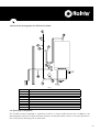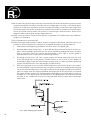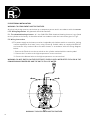
1
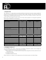
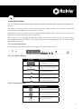
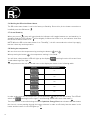
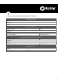
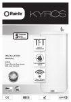
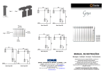
INSTRUCTION
MANUAL
RD SERIES
Digital Electric Water Heater
Wall-hung Unvented
WELCOME
Dear Customer,
Thank you for choosing the RD Series electric water heater, with an exclusive electronic temperature
programmer and made with the highest quality materials.
The RD Series water heaters have exceeded the most stringent quality controls in order to comply
with the most rigorous requirements for both safety and energy efficiency.
Thanks to its exclusive ROINTE Optimizer Energy Plus technology, the electric water heater achieves
the maximum energy saving.
Before using the electric water heater we recommend you read this manual carefully in order to
obtain proper operating information.
IMPORTANT
THIS MANUAL SHOULD BE LEFT WITH THE UNIT AFTER INSTALLATION
02
TABLE OF CONTENTS
1. Introduction
4
2. Component Check List
4
3. General requirements
5
4. Plumbing Installation
6
5. Electrical installation
10
6. Filling and commissioning
11
7. Servicing and maintenance
11
8. Fault finding
12
9. User instructions
13
10. Warranty
16
11. Installation, Commissioning and Service Record
17
03
1. INTRODUCTION
The “RD Series” is a high quality unvented enamelled steel domestic hot water cylinder suitable for
domestic hot water systems where the cold mains water supply is between 3 bar and 9 bar. Reduced
performance is available at lower pressures but the units are not suitable for pressures lower than
1.5 bar and flow rate of 20 litres per minute.
Rointe offers the possibility to acquire all the necessary safety equipment to comply with legislation
governing the installation of such systems.
TECHNICAL SPECIFICATIONS
MODEL NUMBER
RDI50
Storage capacity (litres)
50
Power (w)
1600
Depth (mm)
404
Width (mm)
404
Overall height incl t&p valve
760
Height excl t&p valve
680
Weight when full (kg)
68
Cold feed/hot draw off connections (mm)
15
Maximum water supply pressure (bar)
9
System operating pressure (pre-set) (bar)
3
Expansion vessel charge pressure (bar)
3
Expansion relief valve set pressure (bar)
7
Temperature and pressure relief valve settings:
Lift pressure (bar)
7
Lift temperature (ºC)
90
3bar pressure reducing valve
6 bar expansion relief valve
Expansion vessel ltr
15mm to 22mm Tundish
Isolation valve
Heat up time 15 to 65 ºC (min)
Reheat time for 70% of contents (min)
RDI75
75
2000
404
404
1005
925
100
15
9
3
3
7
RDI100
100
2000
404
404
1165
1085
132
15
9
3
3
7
7
90
7
90
OPTIONAL PACKAGE
•
•
5
•
•
•
•
5
•
•
•
•
5
•
•
PERFORMANCE
120
84
145
101
180
126
2. COMPONENT CHECK LIST
The RD SERIES water heater comes with the following components, please check through the
components supplied and ensure that all parts are present:
a. Water Heater with 1.6 or 2kW sheathed heating elements, digital thermostat, and manual reset
thermal cut-out
b. T/P valve 7 bar 90ºC
c. Installation and user manual
Please contact our customer service department to know how to acquire the safety fittings.
04
3. GENERAL REQUIREMENTS
3.1. The RD SERIES domestic hot water cylinder MUST be installed by a competent person in
accordance with section G3 of the current Building Regulations.
3.2. Important - It is important that the installer reads and understands these instructions, unpacks
and familiarises themselves with the equipment before commencing the installation. Failure to
observe these installation instructions could invalidate the warranty.
3.3. Water supply – The water supply to the cylinder should be potable water direct from a public
mains water supply with any water treatment equipment functioning correctly.
For optimum performance the unit should be fed via a 15 mm diameter supply pipe direct from the
mains water entry point to the property with supplies between 3 bar and 9 bar. The unit can operate
with a minimum supply pressure of 1.5 bar and a flow rate of at least 20 litres per minute, but flow
from the outlets will be low if several outlets are used simultaneously. The cylinder control equipment
is factory set to limit the system operating pressure to 3 bar. The maximum supply pressure into the
pressure-reducing valve is 9 bar.
3.4. Taps and fittings - All taps and fittings incorporated in the unvented system should have a rated
operating pressure of 7 bar or above.
3.5. Location – The unit is designed to be vertically wall mounted, indoors, in a frost-free environment.
When choosing a suitable location for the cylinder, consideration should be given to the routing of
the discharge pipe to a convenient point and also the availability of an adequate power supply for
connecting the sheathed heating elements.
The wall onto which the cylinder is mounted should be of good sound masonry construction capable
of holding the weight of the cylinder when full of water (see technical specifications for weights).
The position of the cylinder should be such that easy access is provided for servicing the controls and
replacing the sheathed heating element should the need arise.
Pipe runs should be made as short as possible and lagged to prevent heat loss.
To allow for servicing and repairs the unit must be mounted at least 300mm above any surface or
object, so that access can be gained to electric connectors and the heating elements may be removed.
The unit should be mounted close to an external wall so that the discharge pipe D2 can be routed to
a safe visible place.
The tundish should be mounted in a visible location so that it may easily be inspected.
3.6. Storage and handling – If the cylinder is not being installed immediately, it should remain in its
carton with all pipe end protective caps in situ to prevent damage. We recommend that the cylinder
be transported to its installation position with the outer carton in place.
3.7. Pipework connections – All Pipework connections to the cylinder MUST be made in accordance
with Fig1.
05
4. PLUMBING INSTALLATION
4.1. Connections. Connections MUST be made to the cylinder in accordance with Fig 1, and Fig 2. A
drain cock (not supplied) should be fitted in the position shown in Fig 1 to facilitate draining of the
cylinder.
4.2. Cold water supply – For best results, the cylinder should be fed by an uninterrupted 15mm supply
pipe into the pressure reducing valve (PRV) with a supply pressure of between 3 and 12 bar maximum.
The cylinder should not be used on any system with a supply pressure below 1.5 bar and a flow rate
of less than 20 litres per minute.
4.3. Temperature and pressure relief valve – The temperature and pressure relief valve (T&P Valve)
is supplied separate. Once the valve is fitted should not be removed from the cylinder or tampered
with in any way. The valve is pre calibrated to lift at 7 bar or 90 degrees centigrade and any attempt to
adjust it will invalidate the warranty and could affect the safety performance of the unit.
The outlet of the T&P valve should be routed in 15mm copper piping in a downward direction alongside
the water heating unit to the tundish. The outlet of the expansion relief valve must be T’d into this pipe
before the tundish so that any water exiting either valve can be seen draining through the tundish–
see fig 2
4.4. Pressure Reducing Valve – The pressure relief valve should be installed in the cold water supply
to the water heating unit with the arrow pointing in the direction of water flow as shown in figure 1.
This can be connected to a supply pressure of between 1.5 and 9 bar.
4.5 Expansion Relief Valve this must be installed between the pressure reducing valve and the water
heating unit in accordance with Figure 1. No other valve should be fitted between this valve and the
cylinder. The expansion relief valve contains a non return valve.
4.6. Expansion vessel – A suitable expansion vessel with a pre-charge pressure of 3 bar is supplied
for fitting to all water heating units in the range. The expansion vessel MUST be fitted between the
expansion relief valve and the cylinder. The expansion vessel MUST be positioned with the entry point
at the bottom.
IMPORTANT: Regular checks must be carried out to ensure that the expansion vessel is correctly
pressurised to 3 bar at all times. The expansion vessel should be installed using a standard
t-connector between the expansion relief valve and the cylinder – see Figure 1.
4.7. Tundish – The tundish must not be positioned above or in close proximity of any electrical current
carrying devices or wiring. The installation should conform with the requirements of item 4.9 below.
06
4.8 Connection arrangement for RD Series Cylinder
Fig 1
1
2
3
4
5
6
7
8
9
10
MAINS COLD WATER SUPPLY (15mm)
STOP COCK (NOT SUPPLIED)
PRESSURE REDUCING VALVE (OPTIONAL)
CHECK VALVE if supplied separately (included in RWC expansion relief valve)
EXPANSION RELIEF VALVE – SET 6 BAR (OPTIONAL)
DISCHARGE PIPE 22mm
DRAIN COCK (NOT SUPPLIED)
TUNDISH. (OPTIONAL)
EXPANSION VESSEL. (OPTIONAL)
T/P RELIEF VALVE. (SUPPLIED)
4.9. Discharge arrangement.
The Tundish must be installed in a position so that it is clearly visible by the user. In addition, the
discharge pipe from the Tundish should terminate in a safe place where there is no risk to persons in
the vicinity of the discharge, be of metal and:
07
(a) Be at least one pipe size larger than the normal outlet size of the safety device unless its total
equipment hydraulic resistance exceeds that of a straight pipe 9 m long, i.e. discharge pipes
between 9 m and 18 m equivalent resistance length should be at least two sizes larger then
the normal outlet size of the safety device, between 18 m and 27 m at least three sizes larger
and so on. Bends must be taken into account in calculating the flow resistance. Refer to the
diagram, tables and worked example detailed below.
(b) Have a vertical section of pipe at least 300 mm long below the Tundish before any elbows or
bends in the Pipework.
(c) Be installed with a continuous fall
(d) Have discharges visible at both Tundish and the final point of discharge, but where this is not
possible or practically difficult, examples of acceptable discharge arrangements are:
•
Ideally below a fixed grating and above the water seal in a trapped gully
•
Downward discharge at low level, i.e. up to 100 mm above external surfaces such as car
parks, hard standings, grassed areas, etc. are acceptable providing that where children
play or otherwise come into contact with discharges, a wire cage or similar guard is
positioned to prevent contact whilst maintaining visibility.
•
Discharge at high level, e.g. into a metal hopper and metal down pipe with the end
of the discharge pipe clearly visible (Tundish visible or not) or onto a roof capable of
withstanding high temperature discharges of water and 3 m from any plastic guttering
system that would collect such discharges (Tundish visible).
•
Where a single pipe serves a number of discharges such as in blocks of flats, the number
served should be limited to not more than six systems so that any installation discharging
can be traced reasonably easily. The single common discharge pipe should be at least one
pipe size larger than the largest individual discharge pipe to be connected. If unvented
hot water storage systems are installed where discharges from safety devices may not
be apparent i.e. in dwellings occupied by blind, or disabled people, consideration should
be given to the installation of an electrically operated device to warn when discharge
takes place.
Fig 2 - Typical discharge pipe arrangement.
08
Warning Notice – The discharge will consist of scalding water and steam. Asphalt, roofing felt and
non-metallic rainwater goods may be damaged by such discharges.
SIZING OF COPPER DISCHARGE PIPE “D2” FOR COMMON TEMPERATURE RELIEF VALVE OUTLET SIZES
Valve outlet size
(diameter, inches)
Min size of
discharge pipe D1
(mm)
Min size of
discharge pipe D2
from tundish (mm)
Max resistance
allowed, expressed
as a length of
straight pipe, i.e. no
elbows or bends
Resistance created
by each elbow or
bend (m)
1/2
15
22
28
35
up to 9
up to 18
up to 27
0.8
1.0
1.4
3/4
22
28
35
42
up to 9
up to 18
up to 27
1.7
1
28
35
42
54
up to 9
up to 18
up to 27
1.4
1.7
2.3
Worked example
The example below is for a ½”diameter temperature relief valve with a discharge pipe (D2) having 4
22mm elbows and a length of 7 m from the tundish to the point of discharge.
The maximum resistance allowed for a straight length of 22mm copper discharge pipe (D2) from a
½”diameter temperature relief valve is: 9.0 m.
Subtract the resistance for 4 No 22mm elbows at 0.8 m each = 3.2 m.
Therefore, the maximum permitted length equates to: 5.8 m.
5.8 m is less than the actual length of 7 m, therefore, calculate the next largest size.
Maximum resistance allowed for a straight length of 28mm pipe (D2) from a ½”diameter temperature
relief valve equates to: 18 m.
Subtract the resistance for 4 No 28mm elbows at 1.0 each = 4 m.
Therefore the maximum permitted length equates to 14 m.
As the actual length is 7 m, a 28mm diameter copper pipe will be satisfactory.
09
5. ELECTRICAL INSTALLATION
WARNING: THIS EQUIPMENT MUST BE EARTHED.
All electrical wiring must be carried out by a competent person and in accordance with the current
I.E.E. Wiring Regulations. All pipework should be earthed!
5.1. The sheathed heating element - A 1.6 or 2kW 230v 50Hz sheathed heating element is pre fitted
to the cylinder at the factory. It should be wired in accordance with the instructions given in Fig 3.
5.2. Wiring instructions
a) The power supply to the heater must be via a double pole isolator switch or controller, having
contact separation of at least 3 mm, using 1.5mm sq. flexible cable, to comply with BS 6141
and must be fully earthed. Wire the water heater in accordance with the wiring diagram
below:
i. Connect the Earth wire to the terminal on the cylinder marked with the earth symbol.
ii. Connect the Live wire to the high temperature cut-out terminal
iii. Connect the Neutral wire to the high temperature cut-out terminal
WARNING: DO NOT SWITCH ON THE ELECTRICITY SUPPLY UNTIL INSTRUCTED TO DO SO IN THE
COMMISSIONING PROCEDURE AND THE UNIT IS FULL OF WATER.
Fig 3
WARNING: THIS APPLIANCE MUST BE EARTHED.
10
6. FILLING AND COMMISSIONING
6.1. Check that the expansion vessel charge pressure is 3 bar.
6.2. Check that all water and electric connections are tight and correctly configured.
6.3. Open the main stopcock and fill the unit. Open successive hot taps starting with the tap furthest
from the heater. Leave each tap open for a few moments to allow all air and debris from the system
to exit. Close all of the taps.
6.4. Turn off the mains water supply to the cylinder and drain the system through the drain cock.
6.5. Refill the cylinder with hot taps open and close when water flows freely.
6.6. Manually lift (by rotating the knob) both the expansion relief and the temperature and pressure
relief valves for a short period to remove trapped air from behind the valve seating and to check the
correct function of the discharge arrangement.
6.7. Check all joints for leaks and rectify as necessary.
6.8. With the heater full of water, turn the thermostat to a point just below its mid point setting and
switch on the electricity supply. Check that the cylinder heats the water and the thermostat operates
when the set temperature is reached. Turn on the hot taps to check that warm water is delivered.
6.9. Check that while the unit is heating up, no water exits from either the expansion relief valve or
the temperature and pressure relief valve. If water does exit through the valves check the expansion
vessel pressure and installation.
6.10. Increase the temperature to maximum and allow the unit to heat and the temperature to
stabilise. Check that no water discharges from the valves. Turn on the hot taps to drain the heater of
hot water. Set the thermostat to the required temperature and allow the heater to reheat ready for
use.
7. SERVICING AND MAINTENANCE
7.1. Servicing and maintenance must only be carried out by a competent unvented hot water heater
installer or by Rointe authorised personnel.
7.2. Before any work whatsoever is carried out on the installation, it MUST first be isolated from the
mains electricity supply.
7.3. Only use spare parts authorised by Rointe. The use of other parts will invalidate the warranty.
7.4. Drain the cylinder – When draining the cylinder, always switch off the boiler and the heating
element first. Turn off the water supply at the stopcock (see Fig 1). Connect a hosepipe to the drain
cock (see Fig 1) and route it to a convenient gully. Open the drain cock and all hot taps that are served
by the cylinder. The cylinder may take several minutes to empty completely.
7.5. In hard water areas it may be necessary from time to time to replace the magnesium anode.
7.6. Remove the cartridge from the pressure reducing valve. Check the strainer and if necessary
remove any debris from in front of it. Replace the cartridge.
11
7.7. Check the charge pressure in the expansion vessel and top up as necessary. The charge pressure
should be 3.0 bar.
7.8. Close the drain cock, disconnect the hose, refit the heating element and close all hot water taps
before reopening the stopcock. Allow the cylinder time to fill whilst checking for any leaks. Release
any air from the system by opening each hot water tap individually, starting with the one furthest from
the cylinder.
7.9. Manually lift the expansion relief and temperature and pressure relief valve one at a time, every
12 months (more frequently in hard water areas) to prevent debris from building up behind the valve
seat. Whilst carrying out this operation, check that the discharge to waste is unobstructed. Check that
each valve seals correctly when released. As the valves are pre-calibrated, they require no further
maintenance.
7.10. Finally, when the heater is full of water switch on the mains electricity supply to the heating
element and the boiler. As the system heats up, check again for any leaks and rectify as necessary.
7.11. In the event of the manual reset cut-out operating, isolate the heater from the mains supply,
investigate and identify the cause of the operation of this cut-out, rectify the fault before manually
resetting the cut-out via the reset button on the cut-out. Finally switch the mains electricity supply
back on.
8. FAULT FINDING
Notice: Disconnect electrical supply before removing any electrical equipment cover.
FAULT
POSSIBLE CAUSE
1.
2.
No hot water
3.
1.
Water from hot taps is cold
2.
Intermittent water discharge
through tundish on warm-up
Continuous water discharge
Programmer if fitted is not
switched on.
High limit thermostat has tripped
1.
Expansion vessel has lost its
charge pressure
1.
Pressure reducing valve (PRV)
not working
Expansion relief valve not seating
correctly
Temperature and pressure relief
valve not seating correctly
2.
3.
12
Mains supply off
Strainer in Pressure reducing
valve blocked
Pressure reducing valve incorrectly fitted
REMEDY
1.
2.
3.
Open stopcock
Turn water supply off, remove
strainer and clean.
Re-fit correctly
1.
2.
Switch on the programmer
Check and re-set
1.
Turn off stopcock, open a hot
water tap, check vessel charge
pressure and recharge to 3 bar
1.
Check pressure from Pressure
reducing valve if greater than 3
bar replace cartridge
Manually lift the valve once or
twice to clear any debris from the
seat otherwise replace valve
2.
9. USER INSTRUCTIONS
9.1. Your RD Series unvented hot water cylinder has been designed to give many years of trouble free
service.
9.2. When a hot tap is turned on there may be a short surge of water, this is quite normal with
unvented systems and does not mean there is a fault.
9.3. When you first fill a basin the water may sometimes appear milky. This is due to very tiny air
bubbles in the water which will clear very quickly.
9.4. If water is seen dripping through the tundish at any time switch off the electricity supply
immediately and call the installer or the Rointe customer service department on the number listed
at the end of this guide.
9.5 Front panel description
The following image shows how the front panel of the water heater looks.
9.5.1 Front panel indicators
SECTION
DESCRIPTION
Set temperature indicator
Amount of hot water available
ON / STAND BY indicator
Heater element in use indicator
Active communication indicator
(not in use at the moment)
9.5.2 Front panel touchpad
SECTION
DESCRIPTION
Increase set temperature button
Decrease set temperature button
ON / STAND BY button
13
9.6 Working the RD series Water Heater
The RD series water heater is set in the factory to Stand by. Due to this, for the heater to work once
installed press the ON button
.
9.7 On and Stand-by
a beep will sound and the indicators will toggle between on and stand-by. In
When you press
stand-by mode the LED indicator will be brightly lit. When the heater is on, the indicator show that
the RD series water heater is on.
NOTE: When the RD series water heater is on “Stand By”, it is still connected to the electricity supply,
but won’t have any active operation.
9.8 Setting the temperature
We can elect to set the temperature by pressing the buttons
When pressing the button
and
.
, the temperature setting is increased.
You will hear a beep and the LED will light up the display
and advancing to the right .
starting from the left at anti-frost
The temperatures that can be set and seen on the display are shown in the following table:
DISPLAY
TEMPERATURE
8º
40º
50º
60º
80º
In order to decrease the set temperature, press the button
and you will hear a beep. The LED will
starting from the right and finishing on the left in anti-frost mode .
switch off
The temperature is controlled using the Rointe Optimizer Energy Plus that activates and deactivates
the electric current passing through the heater element in order to efficiently heat the water in the
heater and the heater in use LED lights up
.
14
9.9 Fault Warnings
During normal equipment use, without any intervention by the user it is possible to detect faults
which are shown using the LEDs.
9.9.1 Temperature probe failure
When the temperature probe fails, the temperature setting LEDs flash every half a second.
9.9.2 Element failure
When an element fails, the heater in use LED
flashes every half a second.
9.9.3 System reset
In order to reset the RD series water heater, press the
immediately access the reset option.
button for 10 seconds and you will
The four LEDs that show the amount of hot water available will be flashing. and when you press the
button, the system will be reset and return to the factory settings.
9.10 Energy tracking by using the optimizer
This product can be incorporated into the software of the ROINTE Optimizer Energy Plus.
15
10. WARRANTY
10.1. Rointe guarantee all electrical and mechanical controls supplied with the cylinder for a period
of 2 years from the date of purchase provided that they have been installed for their intended use by
a competent person and have not been modified in any way.
10.2. In addition Rointe also guarantees the hot water cylinder for a period of 5 years from the date of
purchase against faulty material or manufacture provided that:
a)
It has been installed by a competent person in accordance with this installation manual and
all current regulations and codes of practice at the time of installation.
b)
It has been used solely for the purpose of heating potable water that complies with current
(at the time of installation) EU standards and is not fed with water from a private source.
c)
It has not been modified in any way.
d)
It has not been subjected to excessive pressure or electrolytic action from dissimilar
materials, or attack from any salt deposits.
e)
It has been installed indoors in a frost-free environment.
e)
The warranty card is completed and returned to Rointe within 90 days of installation.
This warranty is not transferable. This warranty does not include claims due to frost or lime scale
damage. Proof of purchase will be required against any claim. This guarantee does not affect your
statutory rights.
For help about the RD Series please contact the Rointe Customer Services Department:
Tlf: 0845 604 5987
Fax: 0208 953 5861
16
11. INSTALLATION, COMMISSIONING AND SERVICE RECORD
CUSTOMER DETAILS
NAME
ADDRESS
TEL No.
INSTALLER DETAILS
COMPANY NAME
DATE
ADDRESS
TEL No.
INSTALLER NAME
REGISTRATION No.
COMMISSIONING ENGINEER (IF DIFFERENT)
COMPANY NAME
DATE
ADDRESS
TEL No.
INSTALLER NAME
REGISTRATION No.
CYLINDER DETAILS
MODEL
CAPACITY (litres)
SERIAL NO.
17
SERVICE RECORD DETAILS
Before completing the appropriate Service Interval Record below, please ensure you have carried
out the service as described in the manufacturer’s instructions and in compliance with all relevant
codes of practice.
It is recommended that your hot water system is serviced regularly and that your service engineer
completes the appropriate Service Interval Record below.
18
SERVICE 1 DATE:
SERVICE 2 DATE:
SERVICE ENGINEER
SERVICE ENGINEER
TEL NO.
TEL NO.
REGISTRATION NO.
REGISTRATION NO.
SIGNATURE
SIGNATURE
SERVICE 3 DATE:
SERVICE 4 DATE:
SERVICE ENGINEER
SERVICE ENGINEER
TEL NO.
TEL NO.
REGISTRATION NO.
REGISTRATION NO.
SIGNATURE
SIGNATURE
SERVICE 5 DATE:
SERVICE 6 DATE:
SERVICE ENGINEER
SERVICE ENGINEER
TEL NO.
TEL NO.
REGISTRATION NO.
REGISTRATION NO.
SIGNATURE
SIGNATURE
SERVICE 7 DATE:
SERVICE 8 DATE:
SERVICE ENGINEER
SERVICE ENGINEER
TEL NO.
TEL NO.
REGISTRATION NO.
REGISTRATION NO.
SIGNATURE
SIGNATURE
19
ROINTE UK
Catalyst House
720 Centennial Court
Centennial Park
Elstree, Herts, WD6 3SY.
CUSTOMER SERVICE
T. 0845 604 5987
FAX NUMBER
F. 0208 953 5861
e-mail: [email protected]
www.rointe.co.uk
MIRDI10V1