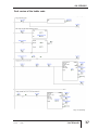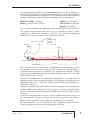
1
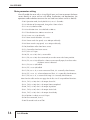
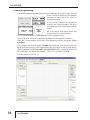
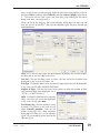
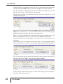
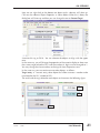
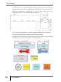
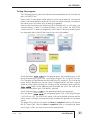
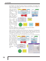
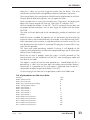
AN-SERV-009
THIS INFORMATION PROVIDED BY AUTOMATIONDIRECT.COM TECHNICAL SUPPORT IS
SUPPLIED "AS IS", WITHOUT ANY GUARANTEE OF ANY KIND. These documents are provided by
our technical support department to assist others. We do not guarantee that the data is suitable for
your particular application, nor do we assume any responsibility for them in your application.
PRODUCT FAMILY: SureServo
Number: AN-SERV-009
Subject: Sureservo with CLICK PLC
Date issued: May-20-2009
Revision: First Edition
This is a similar example as the application note AN-SERV-007 but with a Click PLC.
This simple example demonstrates how to use a Sureservo to control a linear
movement. It is shown how to program a Click PLC, the servo drive and operator
interface. The machine is shown in the simple diagram below:
CLICK PLC
C-more
operator
interface
Servo drive
Tool car
Motor & Gearbox
1200.000mm
1200
Home sensor
This is a device that moves horizontally a 1000 lb tool car, with the help of a chain
and sprockets, through a maximum distance of 830 mm from the Home position, at
a desired distance entered by an operator. This could be for example, a device
similar to a garage door opener but could also be a picking machine or an X-Y table
where only the X axis is shown.
The mechanical department has defined that the sprocket is a 26 teeth, ANSI 40
sprocket and the maximum speed of motion is 1.0 m/second. The acceleration and
deceleration time is 0.6 s. The load is 1000 lb and the friction on the wheels has a
coefficient of about 0.1.
Typically the operator will set the information of the target position on the operator
interface, and he will need to move it in the range of 0 to 830 mm from the Home
position, with the best precision possible (Considering that the chain does not have
stretching).
At the start of the job, when the servo system is enabled, the machine shall go to
the Home position, located at 100 mm from the driving sprocket; the Home is
determined by a proximity sensor. There are also overtravel limit switches.
We have selected to use a PLC C0-05DD1-D and an operator interface EA7-T10C
allowing the operator to control the target position of the tool.
1st Ed.
5/09
Luis Miranda
1
AN-SERV-009
See mechanical considerations on the application note AN-SERV-007. From there it
can be seen that the motor to be used is one of 1 kW.
Use of MODBUS with Sureservo
A characteristic of the Sureservo drive is the possibility of linking the registers of the
servo as slave to a PLC as a master using MODBUS RTU.
What happens if we desire to change the desired position by a distance selected by
an operator?
The desired displacement can be set though an operator interface by selecting one
of the eight positions in the preset target positions. Or can be set in the memory of
the PLC by MODBUS and the operator interface will just write the desired
displacement amount.
The Click PLC can use port 2 with up to 115.2 kBaud. Software allows the
programming of instructions SEND and RECEIVE in a very simple way.
The writing of the target positions is one of many possibilities; it has, of course, the
possibility to read the status, the current position, the current torque, the speed as a
number (and not only through one analog signal). With these data we can change
other parameters such as the acceleration and deceleration, the torque and speed
limits, etc.
A group of status registers (P0-04 to P0-08) are available in the Sureservo drive as
well as a group of block data transfer registers (P0-09 to P0-16).
These consecutive register blocks can be used to group miscellaneous drive
parameters together allowing you to read and write the desired parameters in one
communication block instead of having to use a read or write instruction for each
parameter. These are used extensively in this application note.
You can easily create a control system with servo using a serial MODBUS network.
Let us see in the next pages one way to implement this control project.
Control concept
In this example we will need to run the motor with a target position, given by the
operator, directly in mm, entered in the operator interface. This value should be
scaled to transform the desired linear distance into revolutions and fractions of a
revolution on the servo shaft.
The operator would see where the tool is located at any given time.
The acceleration, maximum speed and deceleration are fix values.
The home search is done by an operator command from the C-more panel.
The brake is released when the servo is enabled.
The motion in this case is ideally suited to be absolute motion with internal registers.
This will define the parameter P1-01 as 1 or 101 and parameter P1-33 as 0.
2
Luis Miranda
AN-SERV-009
Steps for the execution of the control
This is the sequence of operations that shall be followed in this example to get the
system up and running:
- Define the control hardware to be used
- Select and set the communication parameters.
- Read the status of the servo though MODBUS, using the RECEIVE instruction.
- Measure the communication speed in transactions per second.
- Be sure that the servo is set to write data in RAM memory only.
- Make the details of the block transfer parameters.
- Define the values of parameter group P0.
- Define the value of P3-08.
- Define the main parameters in the servo.
- Define the factor of revolutions versus displacement.
- Some C-more programming concepts defined
- Define the digital inputs to be used for commanding the servo.
- Operator would order the system to search for the home position. When the
Home is found and the servo is stopped, the current count shall be “zeroed”.
- Reading the servo status from PLC.
- Operator shall write the desired target position and send to the PLC.
- Create the scaling of the displacement versus rotation of thre servo shaft.
- Test the program together with the servo.
- Add the revolutions and counts of displacement and scale it to show the current
displacement.
- Read servo output data (To be used the status data in P4-09 to create logic for the
operation)
- Test the program and correct any errors.
- Prepare documentation to describe to the operator what it is necessary to operate
the machine. Create operating instructions on the C-more panel as screen text
data on the Operator panel, accessible from the main page.
1st Ed.
5/09
Luis Miranda
3
AN-SERV-009
Harware design: One possibility is to link the PLC to the servo and operator
interface with cables as shown in the following figure, using RS-232 with the cable
SVC-232RJ12-CBL-2. The power supply shown here could be, for example, PS24075D or it could be the one from the Click family, the part C0-01AC.
Connect the servo to the PLC on port 2, wire the inputs and outputs to the Ziplink
module and use port 1 of the PLC for programming it.
Power Supply
24 VDC 120/240
VAC
AC Power
GND
L2
L1
+
–
To supply 24V
for servo brake coil
EA-2CBL
Brake coil
Orange
Yellow
AUTOMATIOND IRECT
MODE
ENTER
NEXT
AC Power
Sureservo
L1
L2
R
T
U
V
W
P
D
C
C
N
2
C
N
3
+24V
0V
C
N
1
S
SVC-232RJ12-CBL-2
EA7-T10C
Operator
interface
ZIPLink Kit Cable connects
to SureServo drive CN1
connector
0V
F1 F2 F3 F4 F5
ZIPLink Kit Terminals
ZIPLink Kit Terminals
VDD
DI2-
COM+
DI1-
DO1+
OB
Brown
Blue
TGND PULSE V-REF /PULSE GND COM-
COM-
Luis Miranda
REVERSE LIMIT
FAULT STOP
4
FORWARD LIMIT
COMHome sensor
Home sensor
+
NPN type
–
AM1-AN-1A
COM- 0Z
COM-
DI6-
DI8-
/OB /OZ
Black
DI8- DI7- DI6- DI5- DI3- PULL HI /SIGN SIGN
DI7-
DO4- DO5- DO5+
/OA
PULL HI
DO2+
DO1-
DO2-
DO3+
DO4+ DO3- DO3+ DO2- DO2+ DO1- DO1+ DI4- DI1- DI2- COM+ GND GND VGND MON2 MON1 VDD T-REF GND VCC OA
AN-SERV-009
Select and set the communication parameters:
Set P3-00 parameter to the desired slave address. In this case we will use the value
2, that is, servo drive slave 2.
Then set a value 3 in P3-01, that defines the transmission rate as 38400 kbps (Kilo
bits per second). This value also must be set in the configuration of PLC port 2. P302 defines the protocol and the configuration of the same port. In this case, let us
select 8. Finally, we set the P3-05 value for RS-232 with a value of 0. This servo
configuration is done with the keypad of the servo drive. Notice that the PLC can
communicate at a higher baud rate of 115.2 kbps.
The communication parameters in the
PLC are configured with the CLICK
programming software and we show here
the values, in the figure below. To get to
this dialog box you have to click on the
menu SETUP and then select COMM
PORT SETUP. Then select the SETUP
button.
See more details on the port 2 set up in
the CLICK user manual. Then we must
connect the PLC with the servo drive.
1st Ed.
5/09
Luis Miranda
5
AN-SERV-009
First, set a value of 10 in the P2-08 parameter with the keyboard to configure all the
values of the servo as default values.
It may appear errors ALE14, ALE15 and ALE13 on the servo drive display, and this
would be normal if not wired properly. You may need to wire the overtravel limit
switches to get rid of the alarms or simply disable the inputs, for now.
The fault ALE14 in the servo display indicates that the overtravel limit switch is
activated, and this is true, since of P2-15 default (that corresponds to the DI6 input
function) it set as 22, P2-16 (that corresponds to the DI7 input function) is set as 23
and P2-17 (that corresponds to the DI8 input function) is set as 21.
In order to clear the faults press the “arrows up and down” keys on the keypad
simultaneously clearing any error that may be there, or it is also possible to power
cycle the servo drive to get the same function.
Next, be sure that the value of the motor code is set in the P1-32 parameter.
Read status from servo on the PLC
Set up the PLC according to the code in next page. This is a simple RECEIVE
instruction that will be executing as often as possible.
Connect the port 2 of the PLC to the servo, as shown previously.
When the servo brake is released by applying 24 VDC to the coil of the servo brake
(Yellow and orange wires on the power cable) and the axis of the motor turns freely,
the data that is contained in the memories P0-00 up to P0-08 can be seen changing.
We will attempt to read data from the servo with MODBUS RTU.
These memories have addresses 40001 up to 40009, as it is in the table below. Note
that the CLick PLC
PLC
Parameter Value MODBUS address
Description
memory
addressing has 6 digits.
P0-00
P0-01
P0-02
P0-03
P0-04
P0-05
P0-06
P0-07
P0-08
2105
14
0
1
0
0
0
0
0
MODBUS
address
2.105
40001
14
40002
0
40003
1
40004
1
40005
0
40006
6
40007
11
40008
13
40009
Parameter Value
P0-00
P0-01
P0-02
P0-03
P0-04
P0-05
P0-06
P0-07
P0-08
6
40001
40002
40003
40004
40005
40006
40007
40008
40009
Luis Miranda
DS1
DS2
DS3
DS4
DS5
DS6
DS7
DS8
DS9
PLC
memory
DS1
DS2
DS3
DS4
DS5
DS6
DS7
DS8
DS9
Software version
Fault code
Display code
Analog monitor
Status monitor 1
Status monitor 2
Status monitor 3
Status monitor 4
Status monitor 5
Description
Software version
Fault code
Drive Status
Analog monitor
Current revolutions
Current counts
Current rpm
Current % torque
DC Bus voltage
The parameters P0-04
to P0-08 should be
changed to be able to
read data that makes
sense.
The adjacent second
table shows what is to
be set on each
parameter with the
help of the keypad.
In order to be able to
read the data from the
servo drive and to
verify
that
the
connections
are
correct, we suggest to
run
the
program
shown in the following
diagram:
AN-SERV-009
Ladder code for Reading data from Servo
This is the explanation of the operation:
On the first scan, the RECEIVE instruction is executed. Data in memory 40001 thru
40008 are read and the content is copied from DS1 to DS8.
C1 is a bit in the PLC that turns ON when there is communication. It is called
"Receiving" and indicates when the PLC is transmitting data through the
communication in port 2, and turns OFF when the data transmission is completed.
Let us say that the PLC scan takes 2 ms; when beginning the transmission the
contact C1 closes indicating that the rung is true to allow the transmission be
executed. When establishing the transmission, C1 turns ON; when the transaction
completes, C1 is OFF again and C2 is turned ON; then another transaction begins
and thus it follows continuously.
Typically the transmission takes more than the PLC scan time. In this case it is
approximately 20 ms. We will see later how to measure this value.
Also, the functions in P0-04 to P0-08 parameters allows to monitor what it is desired
to see in the PLC and later in the
operator panel.
When the parameter changes have
been done, you can move the shaft
of the servomotor if the brake is
released and it will be possible to
observe with Data View that the DS6
memory shows the same number as
the display on the servo when the
shaft of the motor moves. See the
figure below. showing the Data View
information, with nicknames.
This allows checking that the
communication
has
been
established.
1st Ed.
5/09
Luis Miranda
7
AN-SERV-009
Measuring transactions per second
How can we measure the PLC scan time and how many transactions are happening
per second?
Scan time:
Using the menu PLC>Online Project Information,
as in the adjacent figure, to monitor the scan time.
At this time you should have
about 2 ms current scan time.
See at the left figure the dialog
box where it is indicated the
scan time.
Transactions per second:
As we know, when a communication transaction begins, C1 will turn ON, and then we
can count how many times this contact closes in 1 second, for example with a simple
counter. Remember that a counter counts whenever there is a transition of the input from
OFF to ON. See the diagram of the figure below with the corresponding ladder code
and the explanations in each line.
The edge contact SC7 closes
one scan every second; the
copy instruction copies the
current value of the count into
DS1001
Every time C1 closes, the
count increases by one. The
current count of CT1 is
loaded into CTD1.
The count is reset every
second.
Here the RECEIVE instruction
reads
9
words
from
addresses 40001 to 40009 in
the servo and transfer the
data into DS1 to DS9.
C1
turns
ON
while
transmitting data and OFF
when stopped.
8
Luis Miranda
AN-SERV-009
You can read DS1001 in Data View and can see that
the result is about 50 counts every second. Since
there are 1000 milliseconds in a second, 1000/50
ms is approximately 20 ms. See the adjacent figure.
This it is a good method to determine the
transmission speed.
When already proven the comm link between the
PLC and the servo, we should look at what
algorithms to do in the PLC to be able to give the
servo the proper values on the different parameters.
Remember that we are still in the stage of creation
of the program on the master PLC. Also it is
necessary to define what data and how much data will be written to the servo drive.
Data should be written in such a way to avoid that SEND and RECEIVE instructions
execute at the same time. For that purpose we should do an interlock between the
reading and the writing. Note that only one transaction per time is possible. The PLC
will be reading or writing only once at the time, in sequence.
Defining the block transfer parameters
Let us go now to the detail of block transfer registers.
Block transfer parameters P0-09 to P0-16 are “configurable”, that is, the parameters
can be changed to read or write any desired address in the servo drive. Parameters
P0-09 to P0-16 may be changed to our convenience or left as they are.
For reasons to be described later, let us define P0-09 to P0-13 as follows:
Parameter Value Function
MODBUS
address
40010
PLC
Description
memory
DS10 Default is P4-07- Input status
P0-09
21E
As par. P2-30
P0-10
409
As par. P4-09
40011
DS11
Default is P1-09 -Velocity command 1
P0-11
10F
As par. P1-15
40012
DS32
Default is P1-15 -Target 1 revolutions
P0-12
110
As par. P1-16
40012
DS33
Default is P1-16 -Target 1 counts
P0-13
407
As par. P4-07
40013
DS34
Default is P2-36 -Target 1 velocity
In this case, we will be using some of the parameters for other functions explained
after this section. In this example it is convenient to define P0-09 as P2-30, P0-10
as P4-09, P0-11 as P1-15, P0-12 as P1-16 and P0-13 as P4-07. The rest can
continue to be the default value.
Notice that the values there are to be written only by the keypad and this is not
reported by the report that Sureservo PRO software generates.
However, when the values are written there and the servo drive is power cycled, the
setting is retained in EEPROM memory.
1st Ed.
5/09
Luis Miranda
9
AN-SERV-009
The final servo setting is shown in the parameter table at the end of the document.
Note that, as an option to reduce the transactions per second figure, we can
eliminate parameters P0-00 to P0-03 on the reading. We can also decide to read up
to P0-13, thus transferring less than 18 words.
We will change the RECEIVE instruction to read from P0-04 to P0-10, for now,
according to the following table, for convenience in the programming, for reasons
to be seen later in this document.
P0-04
1
MODBUS PLC
Description
address
memory
Current revolutions 40005
DS5 Current revolutions
P0-05
0
Current counts
40006
DS6
Current counts
P0-06
6
Current rpm
40007
DS7
Current rpm
P0-07
11
Current % torque
40008
DS8
Current % torque
P0-08
13
DC Bus voltage
40009
DS9
DC Bus voltage
P0-09
21E
As par. P2-30
40010
DS10
Used as 5 to avoid writing EEPROM
P0-10
409
As par. P4-09
40011
DS11
To read output data thru MODBUS
Parameter Value Function
Explanation on the setting of block transfer parameter P0-09
It is necessary to consider the following: The servo drive has two types of memory:
RAM and EEPROM. In RAM memory data can be written at any time but the
memory EEPROM can only be written to a limited number of times, of the order of
100,000 times.
The parameters that do not change in time are written typically in EEPROM memory
and with this memory it is not necessary to maintain the drive powered. When
powering the servo drive, these values will be still stored in the memory.
This is not possible with RAM memory and the data only stays stored if the servo
drive is powered ON. If we want to write continuously to the drive memory, we
should set the value of P2-30 parameter as 5; but this value is not retained in
memory EEPROM.
Clearly it is not possible that the setting of this value be done by the machine
operator when the servo powers on. Therefore it is necessary to write a value of 5
to this memory when the drive powers ON or otherwise the servo will eventually
reach the limit of writings and the device will not be functional anymore.
One of several ways is to use a compare instruction reading the content of P2-30
parameter and on the basis of that value execute a subroutine with a SEND
instruction writing to that parameter a value of 5. That is, if the reading of that
parameter shows that the value is not 5, we execute a SEND instruction to force a 5
into the same memory.
See the code on the next page for this explanation.
10
Luis Miranda
AN-SERV-009
It can be created an interlock with C4 such that this function is not executed anymore
when P2-30 (MODBUS address 40543 [or 21E in hexadecimal format] has a 5 in its
content.
For that, we will configure P0-09 (Modbus address 40010) with the keyboard (By
default with value 407) as 21E, that causes that this parameter be defined as P2-30.
Then we will include the reading of parameter P0-09 in the RECEIVE instruction.
1 of 4 (Total Pages)
Notice that we had to force a value of 5 into the content of thePage
register
that
corresponds to P2-30. For that, we have to set a register (DS501)with a constant 5.
In order to test this step, turn off the servo and P2-30 will reset to off. Then, when
turning the servo on, you can monitor DS10 with Data View to see the value there.
We added rung 1 for settings we will need later.
1st Ed.
5/09
Luis Miranda
11
AN-SERV-009
You will observe that the PLC did not take notice that the servo was powered off.
Then, it is necessary to create an interlock in such a way that the PLC resets C4
when the servo goes from “servo not ready” to “servo ON”. For this we should read
the output status thru MODBUS. We will discuss this later.
Note that the transactions per second value went down.
Explanation on setting of parameter P3-08
For this step, we have to set P3-08. Let us determine what the value of parameter
P3-08 has to be.
The values of virtual or real digital inputs are defined by the content in P4-07.
P3-08 is a “mask”parameter that allow us to control digital inputs with MODBUS.
Each one of the parameter bits has a predefined function or defined with other
parameters.
If any of the eight less significant bits on P3-08 is a 1, digital inputs DI1 to DI8 are
used as virtual digital inputs with MODBUS; we call them virtual digital inputs as
opposed to real digital inputs. We can imagine each bit of P3-08 as a permissive to
use MODBUS for each one of the defined functions.
The 8 most significant bits have preassigned functions.
Therefore, before defining P3-08, we have to arbitrarily define the digital inputs to
be defined in P4-07. See following table for the selected values for this specific
example:
Bit
Digital
Code
order input
0
1
2
3
4
5
6
7
8
9
10
11
12
13
14
15
DI1
DI2
DI3
DI4
DI5
DI6
DI7
DI8
DI9
DI10
DI11
DI12
DI13
DI14
DI15
DI16
101
104
124
0
0
22
23
21
108
111
112
113
102
127
137
138
Description.
Servo Enable
Clear command
Home sensor
Disabled
Disabled
Reverse overtravel limit switch, opens on overtravel
Forward overtravel limit switch, opens on overtravel
External fault stop, opens on fault
Command Trigger - predefined
PCS0 - Bit de selection 0 de position - predefined
PCS1 - Bit de selection 1 de position - predefined
PCS2 - Bit de selection 2 de position - predefined
Alarm reset- predefined
Home search command - predefined
JOG Forward- predefined
JOG Reverse - predefined
P3-08
assigned
value
1
1
0
0
0
0
0
0
1
1
1
1
1
1
1
1
}
}
}
}
3
0
F
F
This results in a binary string as 1111 1111 0000 0011, which corresponds to
FF03.In this case, we must set P3-08 as FF03. The default value is 0.
12
Luis Miranda
AN-SERV-009
By now we have the MODBUS RTU read function working but we have not
configured the parameters for position operation.
The parameter P3-08 has to be written to the servo with the keypad when P2-30 is
set to 0. The servo register stores FF03 when the servo drive is powered cycled.
Let us go back to the ladder program. The following step shows the definition of a
constant 5 into DS501, an arbitrary register used for storage only.
Notice that in order to force a 5 into DS501 we use a MATH instruction. we could
have used a copy instruction to get the same result.
We can also increase the number of addresses to be read from the servo drive in
rung 5, to include from P0-05 to P0-11. See the change done in the next figure.
1st Ed.
5/09
Luis Miranda
13
AN-SERV-009
Main parameter setting
We will enable the servo with a virtual digital input; we have to connect the home
sensor directly to servo and we will define acceleration and deceleration, the
operation mode and other constants that are listed next (others are left as default):
- P1-01 Operation mode, that by default is 0, set as 1 (Pr mode).
- P1-32 Selection of the stop mode, changed to 1 from value 0.
- P1-33 set as 0, absolute mode
- P1-34 Acceleration time: it was defined as 600 ms.
- P1-35 Deceleration time: 600 ms to arrive at 0.
- P1-36 S-curve: set as 30 arbitrarily.
- P1-47 Home search definition : set as 223.
- P1-48 Home search fast speed; set as 600 rpm arbitrarily.
- P1-49 Home search creep speed; set as 60 rpm arbitrarily.
- P1-50, Revolutions offset from home sensor.
- P1-51, Count offset from home sensor.
- P1-55, left as 2174 rpm.
- P2-10, DI1, set as 101, that is, servo enable
- P2-11, DI2, set as 104, clear command, to zero the counts after home position.
- P2-12, DI3, set as 124, defined as a home sensor normally open, that closes when
the Home sensor is detected
- P2-13, DI4, set as 0, disabled.
- P2-14, DI5 , set as 0, disabled
- P2-15, DI6, set as 22, as reverse overtravel limit; it is a normally closed contact.
- P2-16, DI7 , set as 23, as forward overtravel limit; it is a normally closed contact.
- P2-17, DI8, set as 21, as external fault stop; it is a normally closed contact.
Note from the tables on the next page that the bits 8 to 15 are predefined functions.
- P2-18 , DO1, as 102, that is the output Servo ON.
- P2-19 , DO2, as 109, that is the output Home completed.
- P2-20 , DO3, as 105, that is the output At position.
- P2-21 , DO4, as 107, that is the output Active fault.
- P2-22 , DO5, as 101, that is the output Servo Ready.
- P2-36 Position 1 velocity set to 2174 rpm.
- P2-50 Clear command, set to 1.
- P3-08 DI control mask set to FF03
14
Luis Miranda
AN-SERV-009
The concept of absolute position control will be so that, after the operator enables
the servo drive with an output from the PLC linked to DI1.
The servo system can make the home search after the operator touches one button
in the touch screen panel (as one option; in the example on AN-SERV-007 this is
done with a timer after enabling the servo).
When the servo finds the home position, we will zero the position (0 revs and 0
counts) and then at any time the PLC will be able to write the absolute target
position on P1-15 and P1-16.
P4-07 is the value that contains the digital inputs. Recall that we have arbitrarily
associated the following digital inputs to P4-07:
Bit
order
0
1
2
3
4
5
6
7
8
9
10
11
12
13
14
15
Digital
Code
input
DI1
101
DI2
104
DI3
124
DI4
0
DI5
0
DI6
22
DI7
23
DI8
21
DI9
108
DI10
111
DI11
112
DI12
113
DI13
102
DI14
127
DI15
137
DI16
138
Description.
Servo Enable
Clear command
Home sensor
Disabled
Disabled
Reverse overtravel limit, opens on overtravel
Forward overtravel limit, opens on overtravel
External fault stop, opens on fault
Command Trigger - predefined
PCS0 - Bit de selection 0 de position - predefined
PCS1 - Bit de selection 1 de position - predefined
PCS2 - Bit de selection 2 de position - predefined
Alarm reset- predefined
Home search command - predefined
JOG Forward- predefined
JOG Reverse - predefined
Assigned value
in P3-08
1
1
0
0
0
0
0
0
1
1
1
1
1
1
1
1
PLC
bit
C101
C102
N/A
N/A
N/A
N/A
N/A
N/A
C109
N/A
N/A
N/A
C113
C114
C115
C116
PLC bits are the corresponding bits to be created to link the commands from the Cmore panel.
We have defined the P0-11 parameters and subsequent in such way than they are
the values of position in P1-15 (P0-11), P1-16 (P0-12) and the digital inputs with P013 (that is, P4-07). Therefore, the code of line 9 so that it is written in 3 consecutive
registers and the MODBUS function code will be 16 instead of 6.
In this way, we should set the parameters as follows, with the keypad:
P0-11 will be desired revolutions with the value 10Fhex equivalent to P1-15. This is
the value by default.
P0-12 will be desired counts with the value 110hex equivalent to P1-16. This is the
value by default.
P0-13 will be the word with the digital inputs with the value 407hex equivalent to
P4-07.
The next ones are not important in this specific example.
You may select other block transfer parameters, if it is necessary in your application.
1st Ed.
5/09
Luis Miranda
15
AN-SERV-009
The parameters P0-04 to P0-13 are now set as follows:
1
2
3
4
5
6
7
8
9
10
Parameter
Valu MODBUS
e
address
P0-04
P0-05
P0-06
P0-07
P0-08
P0-09
P0-10
P0-11
P0-12
P0-13
1
0
6
11
13
21E
409
10F
110
407
40005
40006
40007
40008
40009
40010
40011
40012
40013
40014
PLC
Description
memory
DS5
DS6
DS7
DS8
DS9
DS10
DS11
DS12
DS13
DS14
Current revolutions
Current counts
Current rpm
Current % torque
DC Bus voltage
Set not as default, as parameter P2-30
Set not as default, as parameter P4-09
Set as position command 1, revolutions
Set as position command 1, counts
Set as P4-07, digital input word
The idea is to be able to read parameters P0-04 to P0-09, read and write into P0-09
and write into P0-11 to P0-13.
P0-10 is used to read the digital output status at any time.
P0-11 and P0-12 are configured to be able to write the revolutions and the counts
desired, that will correspond to the target position.
We have selected a set of memories beginning in DS5 on the PLC for the purpose
of receiving the data coming from P0-04 to P0-11.
16
Luis Miranda
AN-SERV-009
Factor of revolutions versus displacement
The PLC will have to make some math to relate the linear distance to revolutions
and counts. This is what we will explain now.
Since the circumference of the sprocket is about 330.995 mm or close to 331 mm
and we use a gearbox or ratio 12:1. we can obtain the factor with the following
relationships: 12 revolutions of the servo will result in a distance of 331 mm. That
is, one mm of displacement will be 12.0/331 revolutions or 0.03625 revolutions,
that corresponds to 362.5 counts.
If the operator wants to move to an arbitrary number of, let’s say, 234 mm, the total
counts will be about 234x12/331 = 8.4833 revolutions. This is less than one
revolution on the gearbox output.
If the operator wants to move to another arbitrary number of, let’s say, 687 mm, the
total counts will be about 687x12/331 = 24.9063 revolutions.This is more than one
revolution on the gearbox output.
The error for the total displacement (830 mm) can be determined with the
following: We know that 830/330.995 = 2.500037651. When we calculate
830/331= 2.50755287 and then the error is 0.3 % that is negligible in this case.
This is the math we have to implement in the PLC. Notice that there are integer
revolutions and fractions. The revolution value (8 or 24 respectively in the examples
above) should go to the parameter P1-15. The counts (4833 or 9063 respectively)
will go to the parameter P-16.
The operator will only define the millimeters to be displaced from the Home
position.
Now, recall that we have an operator interface that will write a number, such as 687
in the PLC to an arbitrary memory DS30.
This integer number has to be scaled by 120000/331and separated into 2 numbers.
The ladder code below explains how to to this.
1st Ed.
5/09
Luis Miranda
17
AN-SERV-009
C-more programming
It could be important for operation to show the operator the current target. We will
create a numeric display on the operator
interface that shows the value, similar to
the adjacent figure.
It may also be important to the operator
to show the current position. The servo
will report the current revolutions and the
counts.
We will have to scale those values into
mm to show the current position.
It is time to describe the C-more operator interface programming
We will describe here how to program the objects on the operator interface.
Open the C-more program and create a new project by clicking on button “Start
a project”.
Give a project name (for example, AN-009) then select the HMI; the HMI type will
be the one you are using. In this application note, we used a 10 inch C-more panel.
The PLC protocol will be Automation Direct MODBUS(CLICK) and the baud rate will
be 38400 kbps, the default for the port 1 Click 1 PLC and then click OK.
The next screen will show up:
18
Luis Miranda
AN-SERV-009
Next, we will create a numeric display object to show the current position. Click on
the menu Object and then select Indicator and then Numeric display and click on
it. The cursor will turn into a cross and then drag it by holding the left mouse
button and form a rectangle with it.
When you finish the dragging, the numeric display dialog box will show up and
then you can fill up the data. See it on the adjacent figure. The main features are
explained below:
Label: This is the text that shows on top or bottom to identify the numeric display.
We elect not to use any label in this case.
Text Size: Click on the down arrow to select the Text Size of the number to be
displayed. In this case we will select 16.
16
Data Type: Click on the down arrow to select the type of data that will be displayed.
In this case we will select SIGNED DECIMAL.
Number of Digits: Click on the Up or Down arrows to select the number of Total
and Fractional digits to be displayed. set as
TOTAL 3 & FRACTIONAL 0.
Suffix: Click on the field to enter a common
Suffix value that will always be displayed.
In this case we will select mm.
mm
Data Display Tag: Click on the down arrow
to select a Tag Name. In this case we will
select Current position.
position Click on the
button at the right with 3 dots and other
dialog box will show up, as in the adjacent
figure. Fill up according to the data on the
adjacent figure.
1st Ed.
5/09
Luis Miranda
19
AN-SERV-009
The other fields are not important at this time. You can read more on the online help.
Click on the button ADD to return to the main dialog box and then click OK.
Note that the object is displayed where you have made the rectangle. Drag it to the
top right of the screen. You should see the following
You can set now a Static text to describe what you have on the rectangle. Let us call
CURRENT POSITION.
POSITION
For this action, we will click on the menu Object and then select Text and after that
Static text ... and click on it. The cursor will turn into a cross and then drag it by
holding the left mouse button and form a rectangle with it.
When you finish the dragging, the dialog box will show up and then you can fill
up the text to be shown. In this case, we will write CURRENT POSITION.
Drag it to the left of the numeric display, if necessary; you can also give other size
and shape.
We will do a similar row with the current target. For this, we can copy both objects
and then modify them, as follows (See the figure below to follow the explanation):
Drag a line from the top left to the right under the numeric display and then go to
the menu Edit and hit “Copy”. Then get other submenu “Paste”.
A copy will show up over the original set, offset and showing dots on the corners.
Drag it to under the existing one.
20
Luis Miranda
AN-SERV-009
Now we can right-click on the bottom text object and a submenu will show up.
Click on the submenu Object Properties as shown below. When this is done, the
dialog box will show up and then you can change the text to Current Target.
Associate this tag to DS30. You can relocate the objects to align with the upper
ones.
In the same way, you will change the properties of the numeric display to show now
the current target related to DD1 and the number of digits can be changed to 3.
You may change the frame to other, to distinguish from the previous one.
In the same way, you can continue to set other objects, as follows:
Target entry, as numeric entry, other object that allows to enter a number to be
transferred to the PLC, related to DD1.
The result and the tags related to each object are shown on the following figure
DS20
DS30
DD1
1st Ed.
5/09
Luis Miranda
21
AN-SERV-009
This project can be downloaded to the panel for testing purposes by clicking on the
button “Send Project to Panel”.
You can also simulate the behavior of the panel on the PC by clicking the button
“Simulate panel”. This function provides the possibility to show what you will see
on the panel. For example, you can click on the numeric entry object and the
display will show a keypad that can be clicked to enter a number, as you do on the
panel. More instructions are found in the On-line Help of the software.
We should calculate the current position in DS20, arbitrarily defined, after reading
the revolutions and fractions from the servo drive. See the ladder code on the figure
of next figure, that shows how to to implement this.
We know that the current revolutions are in DS5 and the current counts in DS6.
We executed a calculation to get the current position in mm.
Current position checking: First let us check that the PLC calculation of the current
position in DS20 is correct. Move the shaft of the servo in such a way that there
are 12 revolutions (We know that 12 revolutions will correspond to 331 mm). If
DS20 in Data View shows 331, this is doing the calculation correctly.
22
Luis Miranda
AN-SERV-009
The operator will enter the target in to the numeric entry associated to DD1.
The desired target position is what the operator has entered into the servo. In order
to transfer it, the operator should press the “Send target to servo ” momentary
pushbutton associated to C5. We will test later that the panel communication link
is working together with the servo. The way to do that is to force some values, but
we have not done all the set up so far.
Definition of the commands to the servo
Next, we have to program the different digital inputs and outputs of the servo drive.
Recall that we have previously defined the functions of the operator interface as
follows:
Bit
order
0
1
2
3
4
5
6
7
8
9
10
11
12
13
14
15
Digital
Code
input
DI1
101
DI2
104
DI3
124
DI4
0
DI5
0
DI6
22
DI7
23
DI8
21
DI9
108
DI10
111
DI11
112
DI12
113
DI13
102
DI14
127
DI15
137
DI16
138
Description.
Servo Enable
Clear command
Home sensor
Disabled
Disabled
Reverse overtravel limit, opens on overtravel
Forward overtravel limit, opens on overtravel
External fault stop, opens on fault
Command Trigger - predefined
PCS0 - Bit de selection 0 de position - predefined
PCS1 - Bit de selection 1 de position - predefined
PCS2 - Bit de selection 2 de position - predefined
Alarm reset- predefined
Home search command - predefined
JOG Forward- predefined
JOG Reverse - predefined
Assigned value
in P3-08
1
1
0
0
0
0
0
0
1
1
1
1
1
1
1
1
PLC
bit
C101
N/A
N/A
N/A
N/A
N/A
N/A
N/A
C109
N/A
N/A
N/A
C113
C114
C115
C116
Momentary indicator Button 1 => C101 Servo enable; it shall be set by the operator.
Momentary Button 2=> C109 Move trigger; The trigger shall be commanded by
the operator.
Momentary Button 3 => C113 Alarm reset; this should be commanded by operator
Momentary Button 4 => C114 Home search; this should also be commanded by
operator
Momentary Button 5 => C115 Jog forward; this should be commanded by operator
Momentary Button 6 => C116 Jog reverse; this should be commanded by operator
These commands shall be transferred to the servo with a word in the PLC that is
linked to P4-07, with MODBUS addressing of 41032.
We have to add a JOG forward and a JOG reverse in this project, for the rare case
that the tool car gets the overtravel limit switch activated or any need to test the
motion.
With these considerations we will implement more ladder code in the PLC.
1st Ed.
5/09
Luis Miranda
23
AN-SERV-009
Let us create the buttons.
Button 1- Put the cursor over the Indicator button on the right pane, where it says
Object list and select it then drag it to the left bottom side of the screen 1; it will
pop up the Indicator button dialog box. Fill with the data shown on the figure
below:
The button will activate in toggle mode the bit C101. Servo enable button tagname
is associated to C101; Enabled light tagname is associated to C201 for now.
The button has been programmed; you can transfer the program to the panel and
see how it looks. It should be similar to the next figure:
Space for other buttons
24
Luis Miranda
AN-SERV-009
In the same way, create the rest of the buttons, AS SIMPLE MOMENTARY
PUSHBUTTONS, associating the tag name to the defined C bits. The screen program
will look similar to the following figure:
C116
C115
C101
C101
C113
C109
C114
This can be saved to the C-more panel and it seems a good time to test the
functionality together with the PLC.
Of course, having only 2 communication ports presents small problems. The port 2
will be used for the panel, and then we will have to remove the cable to the servo.
We will not have the servo linked to the PLC, but we can connect the panel to the
port 2 of the servo with the cable EA-2CBL.
Since we have commands in the ladder program to write to a slave in port 2, the PLC
expects a slave connected to it. The C-more panel is a master by itself. There will be
communication errors if we do not disable the communications. One temporary way
to do that is to use normally closed contacts with SC1 in the rungs where there is a
SEND and a RECEIVE instruction. This is what we have done in our test.
In order to test the proper function, let us write a number in the numeric entry, such
as 687, and we will observe that the word DD1 will get the same number. You
should activate the button SEND TARGET TO SERVO for that to execute. The math
in the section Factor of revolutions versus displacement takes the value of desired
target (in mm) into DS32 for the corresponding revolutions and the register DS33 for
the counts.
For example, by entering 331 mm, we can see with Data View that DS32 is 12 and
DS33 is 0, that corresponds to the ratio explained earlier. You can test with any other
acceptable value. See the following figure with Data View for this case.
1st Ed.
5/09
Luis Miranda
25
AN-SERV-009
The pushbuttons can be tested by creating the elements in Data View 2 and seeing
that the C bits will turn ON or OFF depending on the touch of the buttons.
See the figure below for an example in Data View.
The servo enable button is a toggle switch, that is, the bit C101 will be turned ON
one time and then turned OFF when touched again.
The others, including the JOG commands, are momentary pushbuttons that are ON
only when the object is touched.
If you want to see the action in the PLC, you can physically test them by relating,
temporarily, the bits to a physical output of the PLC. When the output is ON, the
corresponding LED will turn ON.
These actions test the objects that have been created in the C-more panel.
These actions complete the test of the C-more and the PLC, for now.
Reading servo output status from PLC
Let us go back to continue making the PLC program. Put the cable going to the
Servo back, and the SC1 N.C. contacts on rungs where there is a SEND or RECEIVE
commans shall be removed.
When the communication has been established, we can see that the baud rate is 47
kbps in the register DS1001 using Data View.
We are reading the outputs in P0-11, or in other words, P4-09.
26
Luis Miranda
AN-SERV-009
Let us analyze what do we want to have here with the help of the following table:
Parameter Value Description
Action expected
P2-18
P2-19
P2-20
P2-21
P2-22
ON when servo is enabled
ON after the Home as been found
ON every time servo reaches the target
ON every time the servo has a fault
ON when servo is powered and no faults
102
109
105
107
101
DO1 defined as Servo ON
DO2 defined as Homing completed
DO3 defined as At position
DO4 defined as Active fault
DO5 defined as Servo ready
Each of the first 5 bits of this word represents the status of the digital outputs (DO’s).
we use the UNPACK COPY instruction to get the data, as follows:
Note that P4-09 was read with MODBUS and transformed into hexadecimal DH1.
Then the content of DH1 was unpacked to C201 to C216. Of course, only bits
C205 to C210 are used.
N/A DI8 DI6 DI4
DI2
How did we test this relationship? In order to turn the
outputs ON, we can use the parameter P4-06. See the
figure at the right to see the next explanation.
N/A
DI7
DI5
DI3
DI1
P4-06 shall be set to 1 to force DO1 to ON. When the
ENTER key is pressed, the servo display will show OP 01 :
Off
On
On
On
Off
and the bit C201 of the PLC will turn ON. In the same Off On On On On
manner, when set to 2, and then when the ENTER key is pressed, the servo display
will show OP 02 and the bit C202 of the PLC will turn ON and so on.
The effect will be seen on the register DS11 on
in C201 to C205 with the help of Data View.
See the adjacent figure.
We are now ready to implement more logic
in the PLC.
We can add some indicators on the c-more screen, as shown below:
1st Ed.
5/09
Luis Miranda
27
AN-SERV-009
Virtual digital input programming
Recall that we want to set the digital inputs with the help of parameter P4-07, that
is written by the C bits defined previously in the C-more panel.
We will read continuously the status of the servo but and we will continuously write
the digital inputs as well as the desired target position.
There are 2 positions and one word with the digital inputs to be written. The 2 word
position information are calculated in DS32 and DS33 and are to be written into
registers P1-15 and P1-16 respectively. These registers are not consecutive, but with
the help of block transfers, we are able to set one SEND writing to P0-11 and P0-12.
We will interlock the RECEIVE instruction with the C bit C8, as in the following figure,
to avoid that the SEND and RECEIVE functions operate at the same time.
In a similar way, we can write the word to change P4-07 to P0-13. P4-07 will take
some values depending on the digital inputs active at any given time.
The rung for the receive instruction has been modified and can be seen in the final
version for the ladder code at the end of the document.
We should prepare the corresponding data to make it logical, with the ladder code
in the following figure.
When the servo is enabled, the PLC output Y4 shall be turned ON to release the
brake. See the logic in the ladder code of the next figure.
28
Luis Miranda
AN-SERV-009
See the figure below for the following explanations:
In order to put the bits into one word, we can use PACK COPY instruction. The bits
C301 to C316 can be PACK COPYed to DH2.
The PACK COPY mode of the COPY Instruction combines the status of up to 16 Source
C Bit Memory Addresses and copy the combined status into a Destination Data
Register (DH2).
The Source field represents the range of the Bit Memory Addresses C301 to C316,
bits that are related to the commands, as shown on the ladder diagram of figure
above.
Destination:
Identify the ending
Destination
Memory Address
(DH1 in this case).
DH2 will be the
memory to be
transferred to the
servo
register
401032 (P4-07).
1st Ed.
5/09
Luis Miranda
29
AN-SERV-009
Now we have to set a word DH2 that has to be transferred to the servo which will
have the bits related to the virtual digital inputs defined in the range C301 to C316.
When this relationship is defined we can SEND the data to the register that
corresponds to P4-07. See the code in the figure below
This is the minimum code that we need. remember to add the END instruction.
We can now test the program together with the operator panel.
In order to be sure that there is communication, we will add a numeric display
showing the transactions per second, as in the figure below:
30
Luis Miranda
AN-SERV-009
Testing the program
The Click programming software can be now disconnected from the PC to make the
port 1 of the PLC free.
Power up the C-more panel and be ready to run the servo motor. Be sure that the
motor is not connected to the load and it is firmly secured to a bracket, to avoid that
the motion may cause some injury or damage to property.
Note that the transactions per second may be in the order of 25 ms (0 if there is no
communication); if there is no communication, turn off and on the RUN/STOP
switch on the PLC in order to, temporarily, make it work. Obviously something else
has to be done there. We will look after this test to fix the problem.
Touch the button S e r vo e n a b l e on the operator panel, that should be gray; at the
touch the button turns green. The virtual digital output C301 in the PLC will turn
ON. The brake will be released with the help of the PLC output Y4. The shaft of the
motor shall be locked since now the servo is enabled and you will hear a typical
sound of current flowing through the windings of the servomotor. Touch again the
S e r vo e n a b l e button on the operator panel to disable the servo. The shaft of the
motor should be loose again if the brake is released.
Touch the button S e r vo e n a b l e on the operator panel for next operations.
Press the button H o m e s e a rch on the operator panel. The virtual digital output
C309 will turn ON. The shaft of the motor shall not be locked anymore and the
Home search will begin to move backwards to detect the position on the home
sensor.
The output DO2 will turn ON when the Home is completed and this will activate
the PLC input C202. After the Home is completed, there is no need to do home
search again, unless you want to return to the zero position.
1st Ed.
5/09
Luis Miranda
31
AN-SERV-009
The indicator at the top of the screen will turn on accordingly.. For example, after
doing home search and the the home has been found, the screen will display an
screen as the following figure.
When the Home is
completed, the PLC
clears the current
counts
(And
revolutions) to get
the 0 counts at this
time and allow a
proper indication of
the current position.
This is done by
commanding
the
clear
command
through MODBUS.
We have transferred
the C bit data to the
servo
though
MODBUS. This is
one way to implement it. Another is to use a real input on the drive.
At this time we can test again the program.
Write a number such 800 mm in the numeric entry “Target entry” by touching the
object. The numeric keypad will show up. Then write “800” and press “ENT”. We
have loaded the number 800 in the PLC-memory and the PLC will scale into
revolutions and send to the servo into parameters P1-15 and P1-16.
It is checked that the number is not greater than 829 mm. If greater or equal than
829, it clamps the
value and forces a
830 on the target.
The scaled data has
been transferred to
the servo and then
the servo is ready to
move from the home
position
to
the
desired
position
indicated as 800
mm.
32
AN-SERV-009
When this is done, we can then trigger the motion with the button. The servo
should move forward to the corresponding number of revolutions and counts.
The numeric display for current position should show the displacement in real time.
To come back to other lower position, we can repeat the action.
Write a number such as 8 mm in the numeric entry “Target entry” by touching the
object. The numeric keypad will show up. Then write “8” and press “ENT”.
We have loaded the number 8 in the PLC. The PLC transforms the new data into
the proper desired revolutions; we can then trigger the motion with the button
TRIGGER.
The servo will move backwards to the corresponding number of revolutions and
counts.
While the servo is enabled, the operator can use the buttons Jog Forward or Jog
reverse to move in one or other direction, for example, to test the overtravel limits.
When connected to the machine, it might be necessary to tune the servo. This can
only be done when the machine is connected. The program Sureservo PRO is very
useful for this operation.
This shows one simple positioning method. Of course, it will depends on the
ingenuity of the programmer to make more complicated logic and to utilize more
features of the C-more panel.
Recall that we have a problem when the system is initially powered up. The
communication was not established until the PLC went into program mode and
then back to run mode.
One option is simply to have the servo powered up 1 second before the PLC is
powered up. It seems that the servo does not accept communications before 1
second after it is powered up. This will require a hardwired timer turned on 1
second after the digital output Servo Ready is ON (DI5).
On the next pages we show the list of parameters and the final ladder code.
List of parameters on the servo drive
Parameter
P0.00 - Software Version
P0.01 - Drive Fault Code
P0.02 - Drive Status (Front panel display)
P0.03 - Analog Monitor Outputs
P0.04 - Status Monitor 1
P0.05 - Status Monitor 2
P0.06 - Status Monitor 3
P0.07 - Status Monitor 4
P0.08 - Status Monitor 5
P0.09 - Block transfer parameter 1
P0.10 - Block transfer parameter 2
P0.11 - Block transfer parameter 3
P0.12 - Block transfer parameter 4
P0.13 - Block transfer parameter 5
1st Ed.
5/09
Value
2105
0
0
0
1
0
6
11
13
21E
409
10F
110
407
Luis Miranda
33
AN-SERV-009
P1.00 - External Pulse Input Type
P1.01 - Control Mode and Output Direction
P1.02 - Velocity and Torque Limit
P1.03 - Output Polarity Setting
P1.04 - Analog Monitor Output Scaling 1 (CH1)
P1.05 - Analog Monitor Output Scaling 2 (CH2)
P1.06 - Analog Velocity Command Low-pass Filter
P1.07 - Analog Torque Command Low-pass Filter
P1.08 - Position Command Low-pass Filter
P1.09 - Preset Velocity Command / Limit 1
P1.10 - Preset Velocity Command / Limit 2
P1.11 - Preset Velocity Command / Limit 3
P1.12 - Preset Torque Command / Limit 1
P1.13 - Preset Torque Command / Limit 2
P1.14 - Preset Torque Command / Limit 3
P1.15 - Position 1 Command (Revolutions)
P1.16 - Position 1 Command (Counts)
P1.17 - Position 2 Command (Revolutions)
P1.18 - Position 2 Command (Counts)
P1.19 - Position 3 Command (Revolutions)
P1.20 - Position 3 Command (Counts)
P1.21 - Position 4 Command (Revolutions)
P1.22 - Position 4 Command (Counts)
P1.23 - Position 5 Command (Revolutions)
P1.24 - Position 5 Command (Counts)
P1.25 - Position 6 Command (Revolutions)
P1.26 - Position 6 Command (Counts)
P1.27 - Position 7 Command (Revolutions)
P1.28 - Position 7 Command (Counts)
P1.29 - Position 8 Command (Revolutions)
P1.30 - Position 8 Command (Counts)
P1.31 - Motor Code
P1.32 - Motor Stop Mode Selection
P1.33 - Position Control Mode
P1.34 - Acceleration Time (Internal Indexer)
P1.35 - Deceleration Time (Internal Indexer)
P1.36 - Accel / Decel S-Curve
P1.37 - Inertia Mismatch Ratio
P1.38 - Zero Velocity Output Threshold
P1.39 - Target Velocity Output Threshold
P1.40 - Max Analog Velocity Cmd or Velocity Limit
P1.41 - Max Analog Torque Cmd or Torque Limit
P1.42 - On Delay Time of Electromagnetic Brake
P1.43 - Off Delay Time of Electromagnetic Brake
P1.44 - Electronic Gear Numerator 1
P1.45 - Electronic Gear Denominator
P1.46 - Encoder Output Scaling Factor
P1.47 - Homing Mode
P1.48 - Homing Velocity 1 - Fast Search Velocity
P1.49 - Homing Velocity 2 - Creep Velocity
P1.50 - Home Position Offset (Revolutions)
34
Luis Miranda
2
101
0
0
100
100
0
0
0
100
200
300
100
100
100
2
253
0
0
0
0
0
0
0
0
0
0
0
0
0
0
21
1
0
600
600
30
5
10
3000
3000
100
20
20
1
1
1
0223
600
60
2
AN-SERV-009
P1.51 - Home Position Offset (Counts)
P1.52 - Regenerative Resistor Value
P1.53 - Regenerative Resistor Capacity
P1.54 - In Position Window
P1.55 - Maximum Speed Limit
P1.56 - Output Overload Warning Threshold
P2.00 - Position Loop Proportional Gain (KPP)
P2.01 - Position Loop Gain Boost
P2.02 - Position Feed Forward Gain (KFF)
P2.03 - Smoothing Constant of Position Feed Forward Gain
P2.04 - Velocity Loop Proportional Gain (KVP)
P2.05 - Velocity Loop Gain Boost
P2.06 - Velocity Loop Integral Compensation (KVI)
P2.07 - Velocity Feed Forward Gain (KVF)
P2.08 - Factory Defaults and Password
P2.09 - Debounce Filter
P2.10 - Digital Input Terminal 1 (DI1)
P2.11 - Digital Input Terminal 2 (DI2)
P2.12 - Digital Input Terminal 3 (DI3)
P2.13 - Digital Input Terminal 4 (DI4)
P2.14 - Digital Input Terminal 5 (DI5)
P2.15 - Digital Input Terminal 6 (DI6)
P2.16 - Digital Input Terminal 7 (DI7)
P2.17 - Digital Input Terminal 8 (DI8)
P2.18 - Digital Output Terminal 1 (DO1)
P2.19 - Digital Output Terminal 2 (DO2)
P2.20 - Digital Output Terminal 3 (DO3)
P2.21 - Digital Output Terminal 4 (DO4)
P2.22 - Digital Output Terminal 5 (DO5)
P2.23 - Notch Filter (Resonance Suppression)
P2.24 - Notch Filter Attenuation (Resonance Suppression)
P2.25 - Low-pass Filter (Resonance Suppression)
P2.26 - External Anti-Interference Gain
P2.27 - Gain Boost Control
P2.28 - Gain Boost Switching Time
P2.29 - Gain Boost Switching Condition
P2.30 - Auxiliary Function
P2.31 - Auto and Easy Tuning Mode Response Level
P2.32 - Tuning Mode
P2.33 - Reserved
P2.34 - Overspeed Fault Threshold
P2.35 - Position Deviation Fault Window
P2.36 - Position 1 Velocity
P2.37 - Position 2 Velocity
P2.38 - Position 3 Velocity
P2.39 - Position 4 Velocity
P2.40 - Position 5 Velocity
P2.41 - Position 6 Velocity
P2.42 - Position 7 Velocity
P2.43 - Position 8 Velocity
P2.44 - Digital Output Mode
1st Ed.
5/09
0
40
60
100
2174
120
35
100
5000
5
500
100
100
0
0
2
101
104
124
0
0
0
0
0
102
109
105
107
101
1000
0
2
0
0
10
10000
0
HEX 44
0
0
5000
30000
2174
400
1000
1000
1000
1000
1000
1000
0
Luis Miranda
35
AN-SERV-009
P2.45 - Index Mode Output Signal Delay Time
P2.46 - Index Mode Stations
P2.47 - Position Deviation Clear Delay Time
P2.48 - Backlash Compensation (Index Mode)
P2.49 - Jitter Suppression
P2.50 - Clear Position Mode
P2.51 - Servo Enable Command
P2.52 - Dwell Time 1 - Auto Index Mode
P2.53 - Dwell Time 2 - Auto Index Mode
P2.54 - Dwell Time 3 - Auto Index Mode
P2.55 - Dwell Time 4 - Auto Index Mode
P2.56 - Dwell Time 5 - Auto Index Mode
P2.57 - Dwell Time 6 - Auto Index Mode
P2.58 - Dwell Time 7 - Auto Index Mode
P2.59 - Dwell Time 8 - Auto Index Mode
P2.60 - Electronic Gear Numerator 2
P2.61 - Electronic Gear Numerator 3
P2.62 - Electronic Gear Numerator 4
P2.63 - Velocity and Position Deviation Scaling Factor
P2.64 - Advanced Torque Limit Mixed Mode
P2.65 - Special Input Functions
,
P3.00 - Communication Address
P3.01 - Transmission Speed
P3.02 - Communication Protocol
P3.03 - Communication Fault Action
P3.04 - Communication Watchdog Time Out
P3.05 - Communication Selection
P3.06 - Reserved
P3.07 - Communication Response Delay Time
P3.08 - Digital Input Software Control Mask
P4.00 - Fault Record - Most recent (N)
P4.01 - Fault Record (N-1)
P4.02 - Fault Record (N-2)
P4.03 - Fault Record (N-3)
P4.04 - Fault Record (N-4)
P4.05 - JOG Function
P4.06 - Force Outputs Command
P4.07 - Input Status
P4.08 - Reserved
P4.09 - Output Status
P4.22 - Analog Velocity Input Offset
P4.23 - Analog Torque Input Offset
36
Luis Miranda
1
6
0
0
0
1
0
0
0
0
0
0
0
0
0
1
1
1
0
0
HEX 0
2
3
8
0
0
0
0
0
HEX FF03
14
11
11
11
13
100
0
0
0
20
0
0
AN-SERV-009
Final version of the ladder code
Main Program(Page 1 of 4
Page 1 of 4 (Total Page
1st Ed.
5/09
Luis Miranda
37
AN-SERV-009
Main Program(P
Page 2 of 4 (T
38
Luis Miranda
AN-SERV-009
Sprocket click
Main Program(Page 3 of 4)
Page 3 of 4 (Total Pages)
1st Ed.
5/09
Luis Miranda
39
AN-SERV-009
Sprocket click
Main Program(Page
Page 4 of 4 (Tota
40
Luis Miranda