1
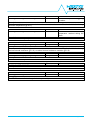
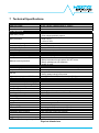
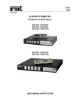
a DCU20 12/24V 20A High Performance DC-UPS User Manual DCU20 User Manual rev. 16 Page 1/29 DISCLAIMER NEXTYS reserves the right to make changes without further notice to any products herein. NEXTYS makes no warranty, representation or guarantee regarding the suitability of its products for any particular purpose, nor does NEXTYS assume any liability arising out of the application or use of any product, and specifically disclaims any and all liability, including without limitation consequential or incidental damages. “Typical" parameters which may be provided in NEXTYS data sheets and/or specifications can and do vary in different applications and actual performance may vary overtime. All operating parameters, including “Typicals", must be validated for each customer application by customer's technical experts. NEXTYS does not convey any license under its patent rights nor the rights of others. NEXTYS products are not designed, intended, or authorized for use as components in systems intended for surgical implant into the body, or other applications intended to support or sustain life, or for any other application in which the failure of the NEXTYS product could create a situation where personal injury or death may occur. Should Buyer purchase or use NEXTYS products for any such unintended or unauthorized application, Buyer shall indemnity and hold NEXTYS and its officers, employees, subsidiaries, affiliates, and distributors harmless against all claims, costs, damages, and expenses, and reasonable attorney fees arising out of, directly or indirectly, any claim of personal injury or death associated with such unintended or unauthorized use, even if such claim alleges that NEXTYS was negligent regarding the design or manufacture of the part. The Customer should ensure that it has the most up to date version of the document by contacting its local NEXTYS office. This document supersedes any earlier documentation relating to the products referred to herein. The information contained in this document is current at the date of publication. It may subsequently be updated, revised or withdrawn. All Trade Marks recognized. Specifications and information herein are Subject to change without notice. DCU20 User Manual rev. 16 Page 2/29 TABLE OF CONTENTS 1 2 3 System description ...........................................................................................................................................5 Features and benefits .......................................................................................................................................6 Functional description ......................................................................................................................................7 3.1 Remote monitoring and controlling .............................................................................................................7 3.1.1 USB ......................................................................................................................................................7 3.1.2 Digital input...........................................................................................................................................7 3.1.3 Dry contact outputs ..............................................................................................................................7 3.2 Backup ........................................................................................................................................................8 3.3 PC shutdown and automatic restart ...........................................................................................................8 3.4 Battery health monitor...............................................................................................................................10 3.5 Battery resistance measurement ..............................................................................................................11 3.6 Battery charger .........................................................................................................................................11 3.7 Coulomb counter ......................................................................................................................................12 3.8 Cold start ..................................................................................................................................................13 4 Installation ......................................................................................................................................................14 4.1 Connecting the input to the power supply ................................................................................................14 4.2 Connecting the load ..................................................................................................................................14 4.3 Connecting the battery .............................................................................................................................14 4.4 Connecting the temperature sensor .........................................................................................................14 4.5 Connecting the INHIBIT input ...................................................................................................................15 4.6 Dry contacts ..............................................................................................................................................15 4.7 Battery sense connection .........................................................................................................................15 5 User interface .................................................................................................................................................16 5.1 Status ........................................................................................................................................................17 5.2 Settings .....................................................................................................................................................17 5.2.1 Input nominal voltage .........................................................................................................................18 5.2.2 Battery chemistry ...............................................................................................................................18 5.2.3 Battery nominal voltage ......................................................................................................................18 5.2.4 Battery capacity ..................................................................................................................................18 5.2.5 Battery charge voltage .......................................................................................................................18 5.2.6 Battery charge current........................................................................................................................18 5.2.7 Battery deep discharge voltage .........................................................................................................18 5.2.8 Battery nominal internal resistance ....................................................................................................19 5.2.9 Battery maximal internal resistance variation ....................................................................................19 5.2.10 Battery maximum temperature .......................................................................................................19 5.2.11 Battery minimum temperature .....................................................................................................19 5.2.12 Battery lifetime ................................................................................................................................19 5.2.13 Maximum backup time ....................................................................................................................19 5.2.14 Inhibit polarity ..................................................................................................................................20 5.2.15 Screen contrast ...............................................................................................................................20 5.2.16 Screen backlight .............................................................................................................................20 5.2.17 Screen timeout ................................................................................................................................20 5.2.18 Buzzer state ....................................................................................................................................20 5.2.19 Date.................................................................................................................................................20 5.2.20 Time ................................................................................................................................................20 5.2.21 PC shutdown enable .......................................................................................................................21 5.2.22 PC shutdown delay .........................................................................................................................21 5.2.23 PC shutdown time ...........................................................................................................................21 5.2.24 PC restart minimum OFF time ........................................................................................................21 5.2.25 PC OFF detection current threshold ...............................................................................................21 5.2.26 PC OFF detection timer ..................................................................................................................21 5.2.27 Relay 1 (Ready) ..............................................................................................................................21 5.2.28 Relay 2 (Backup) ............................................................................................................................22 5.3 Info ............................................................................................................................................................22 5.3.1 Firmware version ................................................................................................................................22 5.3.2 Serial ..................................................................................................................................................22 5.3.3 Name ..................................................................................................................................................22 5.3.4 Power ON cycles counter ...................................................................................................................22 DCU20 User Manual rev. 16 Page 3/29 5.3.5 Operating time ....................................................................................................................................22 5.3.6 Battery installation date ......................................................................................................................22 5.3.7 Battery operating time ........................................................................................................................23 5.4 Logs ..........................................................................................................................................................23 5.5 Wizard .......................................................................................................................................................23 6 Events and Alarms .........................................................................................................................................24 7 Technical Specifications .................................................................................................................................28 DCU20 User Manual rev. 16 Page 4/29 1 System description The DCU20 is a microprocessor controlled DC UPS rated 20A (rating of the power supply connectable to the input) usable in systems with a nominal voltage between 12V and 28V. The DCU20 monitors the voltage coming from a DC power supply and in case of power failure a backup battery is connected to the load. In normal condition the battery is kept charged by an integrated battery charger supporting various battery chemistries such Lead-Acid, NiMH, NiCd and Lithium. 1. Alarm LED indicator: It is ON when the unit is in backup. It blinks at 1Hz rate in case of 1 error. 2. USB Port: Used to connect a PC running the POWERMASTER application for remote 2 10 monitoring and controlling. Firmware update is also possible through USB connection. 11 3. Temperature sensor connection: Used to connect a temperature sensor (P/N: WNTC12 3 2MT) to measure the battery temperature for protection and temperature compensated charge method. 13 4. Relays dry contacts: 2 relays are present for 4 remote monitoring. See §3.1 for more details. 5 5. Inhibit input: A signal between 5VDC and 6 30VDC applied to this input inhibits the backup function; this input is programmable to be active high or active low (see §4.5). 7 6. “Battery sense” connection: Used to accurately sense the battery voltage by 8 considering the cables voltage drop. It is recommended to use this input when the 9 battery internal resistance measurement is needed (see §4.7). 7. Input connection: 2 poles are provided for input connection. This must be connected to a power supply rated 12…28VDC with a Figure 1: Front panel view maximum rated current of 20A (see §4.2). 8. Output connection: 2 poles are provided for output connection. It must be connected to the load to be backed up with a maximum rated current of 20A (see §4.2). 9. Battery connection: 2 poles are provided for battery connection. This must be connected to the battery. Although the unit is protected, please respect the correct polarity. (see §4.3) 10. Display “Input” area: provides information regarding the unit’s input (see §5.1). 11. Display “Output” area: provides information regarding the unit’s output (see §5.1). 12. Display “Battery” area: provides information regarding the battery (see §5.1). 13. Control keys: 4 push buttons are provided to navigate through the menus and to select the various functions. DCU20 User Manual rev. 16 Page 5/29 2 Features and benefits The main features are: Integrated battery charger for multi-chemistry batteries with charging current up to 5A. Automatic sensing of input voltage, load current and battery current. Protections against battery reverse polarity connection and over current when operating from the battery. Battery “health monitoring” system: measuring battery internal resistance, battery temperature and providing a Coulomb counter. User settable maximum backup time. Remote input to inhibit the UPS function. Connection of a battery thermal sensor (optional). Integrated data logger with time stamp: all events / errors are logged in the internal memory and downloadable through the USB interface. Automatic PC shutdown/restart function (see §3.3) Embedded user interface: 4 buttons and 1 color graphic CSTN LCD, Displays the set-up, status, measures and alarms Online device configuration. USB port for remote monitoring and configuration. Dry contacts for status monitoring “POWERMASTER” PC application: Connection through USB interface. Remote monitoring and configuration. Firmware upgrade. Same functionalities of the embedded user interface with the ease of the PC benefits. DCU20 User Manual rev. 16 Page 6/29 3 Functional description A simplified block diagram of the DCU20 is shown in Figure 2. A IN A V V 5A Battery C harger TH R Buz z er Battery health Monitor Reverse Polarity BATT OUT A Thermal D is play U SB Buttons R elay s U SB R EAD Y BAC KU P V Microprocessor Figure 2: DCU20 simplified block diagram DCU20 is a high performance digitally controlled DC-UPS that can be used in any DC system with a rated voltage between 12V and 28V and up to 20A of input current. It includes a battery charger capable of charging Lead-Acid, Ni-MH and Li-ION batteries with a rated voltage between 12V and 28V and able to deliver a charge current up to 5A. The input voltage is continuously monitored by the microprocessor. In case of a power outage the battery is connected to the load instantaneously through an active switch, reducing the power loss to a minimum. The product offers additional features to improve the performance and the reliability of the system, which are described below. 3.1 Remote monitoring and controlling 3.1.1 USB The USB interface allows the communication with the proprietary POWERMASTER software (available for download at www.nextys.com) which allows the full control and monitoring of the DCU20 unit with the ease of the PC. 3.1.2 Digital input An opto-isolated input allows the inhibition of the backup function. The polarity of the input can be defined using the Inhibit polarity setting (see §5.2.14). 3.1.3 Dry contact outputs 2 relays are present on the DCU20. User can chose which event activates the relay and the polarity. The list of events is the following: DCU20 User Manual rev. 16 Page 7/29 Name Backup SoC < 25% (Low Battery) Battery life time expired Battery Ri too high Battery failure Battery under voltage Battery backup time left < 25% PC OFF signal Description Active when the system is running on the batteries. Active when the State of Charge (SoC) of the battery is below 25%. Active when the battery life time counter is exceeding the value specified on §5.2.12 Active when the measured battery internal resistance (Ri)> alarm threshold. The threshold is specified using setting §5.2.8 and §5.2.9. Active when the battery could not be charged correctly. Active when the battery voltage is below the value specified on §5.2.7 Active when the remaining backup time is higher than the 75% of the maximal backup time defined on §5.2.13 Activated by the PC shutdown and automatic restart function. See §3.3 for details. Default setting Relay 2 Unused Relay 1 Relay 1 Relay 1 Unused Unused Unused Table 1: Relays signals By default both relays polarity is set to NC (Normal Close). 3.2 Backup The system is in backup if the supply for the output is sourced from the battery (input supply missing). During backup the battery is monitored continuously to prevent over discharge (see §5.2.7). A programmable backup timer (see §5.2.13) is also implemented in order to fix a maximum backup time during power outages. This allows preserving the battery life and shortening the recharge time, avoiding discharging the battery when not needed. During backup the internal Coulomb counter is used to give an estimation of the residual charge of the battery, this information is given to the user on the LCD in form of remaining % and through the ready relay which starts toggling at 1Hz once the battery charge is < 20%. 3.3 PC shutdown and automatic restart PC shutdown: In case the DCU20 is used to supply a PC it is possible to automatically shut down the PC after an adjustable time of backup. For this the PC must run the POWERMASTER application (provided free) and must be connected through USB. Optionally POWERMASTER can call a task on the PC before shutting down, for example to backup some sensitive data. Automatic restart: DCU20 is able to automatically restart a PC which was powered OFF by mistake, for example in case of the Operating System (OS) crash. The user may adjust an output current threshold and a timer used for detecting the PC OFF status. In order to restart the PC the DCU20 toggles the output OFF and then ON again. User must enable in the PC BIOS the automatic start in case of supply ON. Note: The DCU20 cannot interrupt the supply flow from the input to the output. Therefore the user must use one of the DCU20 available relays (by activating the PC OFF signal on it) in order to enable automatic PC restart when the input supply is present. The relay contact (rated 2A/30Vdc) must be wired in series to the device output using a 4A fast cartridge fuse (Littlefuse 0217004.HXP or equivalent). Be careful to respect maximum current rating of the fuse. DCU20 User Manual rev. 16 Page 8/29 In case the load (PC) current exceeds the DCU20 dry contact rating the use of an external relay with suitable current/voltage rating is needed, relay coil voltage shall match output voltage. It should be driven by the DCU20 internal dry contact. OUTPUT+ Fuse 5x20 4A Fast Relay OUTPUT+ OUTPUT- OUTPUT- Figure 4: External relay Figure 3: Internal relay The diagram below shows the DCU20 behavior when Shutdown and automatic restart is enabled. Input voltage E1 Output voltage Ioff E3 E2 Output current PC status E4 PC OFF signal Time T1 T2 ... T3 ... T4 T3 Figure 5: Shutdown and restart chart Parameter Name E1 Backup E2 Automatic PC shutdown E3 Unexpected PC shutdown E4 PC restart DCU20 User Manual rev. 16 Description Power failure on the line happens. System enters backup mode. The POWERMASTER sends a shutdown command to the PC. Optionally: a task is called before shutdown. The PC shutdowns in an unexpected way, for example caused by OS crash. DCU20 detect the PC being OFF because the output current was lower than Ioff current threshold for T4 time. As a consequence DCU20 generates an ON->OFF->ON cycle on its output. Page 9/29 T1 PC shutdown delay T2 PC shutdown time T3 PC restart minimum OFF time T4 PC OFF detection timer Ioff PC OFF detection current threshold User settable (§5.2.22). Time between start of backup and start of PC shutdown procedure. User settable (§5.2.23). Time between start of shutdown procedure and output voltage OFF. This time must be set longer than the maximum time the PC takes to complete the shutdown. User settable (§5.2.24). T3 is the delay used between the return of the input voltage and the activation of the output. The same time is used by the automatic restart function as power OFF time to restart the PC. The value must be big enough for the PC to detect the supply ON->OFF->ON cycle to restart. User settable (§5.2.26). Minimum time at which the output current must be below the Ioff current threshold to trigger the automatic PC restart (PC supply ON->OFF->ON cycle). User settable (§5.2.25). Current threshold used to detect PC OFF status. This value must be lower than the minimum PC current consumption when this is ON. Table 2: Shutdown and restart The parameters are settable through the DCU20 LCD or using the POWERMASTER application as shown on the image below. The checkbox “Run on startup” must be checked on POWERMASTER when PC shutdown function is used, select “Start in tray” to start in minimized into the windows system tray. To inhibit the software from calling the shutdown command user can select the “Inhibit shutdown” check box. Figure 6: PC shutdown settings 3.4 Battery health monitor The battery health monitor is composed of: Internal resistance (Ri) measurement: The resistance is periodically measured. The internal resistance is a good indicator of the battery health status; a sudden increase of the internal resistance indicates a potential problem on the battery or on the battery wiring (see §3.5). Temperature (T) measurement: The battery temperature is monitored through an optional temperature sensor (P/N: WNTC-2MT). The battery charger takes into account the battery DCU20 User Manual rev. 16 Page 10/29 temperature and provides a temperature compensated charging voltage. In case of over temperature the system disconnects the battery to prevent damage. Coulomb counter: It allows having a quick estimation of the remaining battery capacity and consequently the available backup time. Deep discharge protection: It protects against the deep discharge of the battery which can lead to its irreversible damage. 3.5 Battery resistance measurement The battery internal resistance (Ri) is measured by injecting a defined AC current through a constant current source (CCS) in the battery and measuring the AC voltage drop across the battery terminals. The principle is represented in Figure 7. The injected AC current I(AC) is flowing also through the cables + connectors resistance - “Rcables”. Rcables I(AC) - + Constant Current Source (CCS) Ri Battery Figure 7: Internal resistance measurement Without using the battery sense connection as shown in Figure 9 the AC voltage drop is measured across the battery connection terminals on the DCU20. The measured resistance will be in this case: Rmeasured=Ri+Rcables. When high Ah batteries and / or small and long cables are used Rcables can be > Ri. Anyhow a connection problem as for example a loose contact can be detected by this measurement method. By using the battery sense connection (a “Kelvin” type connection) as shown in Figure 10 the AC voltage drop is measured directly at the battery terminal. In this case the measured resistance is exactly the battery internal resistance Ri, independently on the cables length and size. It is recommended to use this method to have an accurate reading of the battery internal resistance and thus an accurate prediction of the battery health status. If the battery sense cables length is > 2m it is recommended to twist the 2 wires together in order to increase the noise immunity. 3.6 Battery charger The battery charger supports various chemistries such Lead-Acid, Nickel, Lithium and every other battery chemistry assuming that the charging voltage and charging current values are provided by the battery manufacturer. The charging algorithm is shown on Figure 8. Other charging algorithms can be implemented by request. The user must set to the unit the following parameters to allow the charger to perform correctly: Battery chemistry: selectable between Lead-Acid, Nickel, Lithium (see §5.2.2). Battery nominal voltage: between 12V and 28V (see §5.2.3). Battery capacity: between 1.2Ah and 150Ah (see §5.2.4). Battery charging voltage: provided by the battery manufacturer (see §5.2.5). DCU20 User Manual rev. 16 Page 11/29 Battery charging current: provided by the battery manufacturer (see §5.2.6). Battery deep discharge voltage (see §5.2.7). The battery charger automatically reduces the current to avoid exceeding the maximum input current (20A) in case of high current load. For example if the load is consuming 19A and the charger current is set to 3A, the charger current is automatically reduced to 1A to avoid the 20A input current limit. The charger voltage is independent on the input voltage (power supply), and is user settable. Constant current Voltage Constant voltage Maintenance User settable charge voltage User settable charge current Current Time Figure 8: Battery charging algorithm The battery charge terminates in case at least one of the following conditions are satisfied: Low current: The measured battery current is lower than 10% of the “Battery charge current”. Timer: the charge is terminated after the battery has been charged for a predetermined amount of time. The value is automatically calculated by the device. For Nickel batteries only the following conditions are also checked: Temperature Cutoff (TCO): The battery temperature if higher than the “Battery maximal temperature” (§5.2.10) minus 3°C for more than one minute. For example if the maximal battery temperature is set to 60°C, the charge terminates in case the temperature is higher than 57°C. Rate of Temperature Increase (ΔT/dt): The battery temperature is rising at a rate equal or superior then 1°C/min. To avoid unattended end of charge don’t place the system on an ambient with rapid changes of temperature (for example exposed to direct sunlight). Warning: In order to avoid potentially hazardous situations including fire hazard, safety recommendations must be followed. Only authorized staff can install the unit. Warning: For Lithium cells the balancing and protection circuit must be included in the battery pack. For nickel batteries the use of the external temperature sensor is mandatory. The sensor must be placed in contact with the battery. 3.7 Coulomb counter DCU20 measures the current flowing from/to the battery to keep track of the capacity available on the battery. The capacity is measured in Ampère Hours [Ah]. The value shown is based on the following assumptions: The value shown is just informative and does not represent the real state of charge of the battery in some circumstances, for example if the battery is damaged. DCU20 User Manual rev. 16 Page 12/29 When the battery is connected for the first time or the system starts from OFF, the system assumes the battery is fully discharged and start with 0Ah counter. For Lead acid batteries only, during battery charge an approximation of charge is done checking the battery voltage. Once the battery is fully charged the system sets the counter to the nominal capacity specified by the user (§5.2.4). 3.8 Cold start The cold start is a procedure that allows turning ON the UPS without the input power. This procedure is used to turn ON the UPS to operate during a power interruption or to determine if the UPS will not turn ON due to a bad input power. This practice is also a method to see if the battery connected to the DCU20 is functional. In cold start the DCU 20 will remain ON for at least 60 seconds independently from the battery voltage being under the deep discharge threshold, the inhibit input and the backup timer. After the first 60 seconds the device stays ON until the battery is not deep discharged, the “Max backup timer” is not expired or the inhibit input is not active. If the input supply returns during cold start the device reverts to normal operation. To cold start the DCU20: Press and HOLD simultaneously the menu button and OK button until you see the welcome message on the screen. On the status screen the input voltage status is indicated as “COLDSTART”. RELEASE the buttons. DCU20 User Manual rev. 16 Page 13/29 4 Installation Warning: In order to avoid potentially hazardous situations including fire hazard, safety recommendations must be followed. Only authorized staff can install the unit. 4.1 Connecting the input to the power supply The DCU20 must be connected to a DC power supply rated between 12VDC and 28VDC with a maximum output current of 20A. Use only 60/75 Class I copper 1.5…2.5mm 2 wires stripped 6...7.5mm. The tightening torque must be 0.5…0.6Nm. Please respect the wiring polarity! Note: The input current is equal to the load current plus the current needed by the battery charger to recharge the battery. Caution: This input is designed to be connected ONLY to a short circuit protected power supply; connecting a battery to this input or other DC sources with not defined current limitation may seriously damage the unit or the load and even result in fire hazard. 4.2 Connecting the load The DCU20 must be connected to a DC load rated between 12VDC and 28VDC / maximum 20A. Use only 60/75 Class I copper 1.5…2.5mm2 wires stripped 6...7.5mm. The tightening torque must be 0.5…0.6Nm. Please respect the wiring polarity! Please check the load and the power supply are rating compliant. 4.3 Connecting the battery The DCU20 must be connected to a battery with nominal voltage between 12VDC and 28VDC with up to 150Ah capacity. Higher capacity batteries can also be used at the expense of a longer charging time. Use only 60/75 Class I copper 1.5…2.5mm2 wires stripped 6...7.5mm. The tightening torque must be 0.5…0.6Nm. Caution: The battery shall be connected to the DCU20 through a 30A ATO fuse (or equivalent). Even is the unit is electronically protected against short circuit it is mandatory to use a fuse for safety reasons. Please respect the wiring polarity! Avoid keeping the DCU20 connected to the battery for long time when not used. Although the current consumption from the battery when the unit is OFF is very low (about 30µA) it can discharge the battery in the long time. 4.4 Connecting the temperature sensor An optional temperature sensor (P/N: WNTC-2MT) can be connected to its input on the front panel. The temperature sensor is provided with 2m long cables and must be fixed to the battery body to measure its temperature (an adhesive pad can be used). When the sensor is connected the battery temperature is automatically displayed on the LCD and a temperature compensated charge is activated when charging Lead-Acid batteries. DCU20 User Manual rev. 16 Page 14/29 4.5 Connecting the INHIBIT input An opto-isolated digital input is provided. A digital signal between 5VDC and 30VDC must be applied to this input to enable the INHIBIT function. By default when the signal is 0V (or the INHIBIT input is not connected) the unit will switch the load to the battery as soon as the input voltage is no more present. Applying a signal to this input inhibits the backup function and the load can be switched OFF as soon at the input fails with no battery backup. The polarity of this input can be changed as explained in §5.2.14. 4.6 Dry contacts 2 relays’ dry contacts are provided on the DCU20. Connect the 2 relays dry contact using 60/75 Class I copper 0.15…0.5mm2 wires stripped 7...8mm. The connector is provided with spring terminals. Note: the 2 relays contacts have one pole in common. 4.7 Battery sense connection Rcables Rcables - + Ri Battery Figure 9: Battery connection without sense - + Ri Battery Figure 10: Battery connection with sense The battery sense connection is optional and it is recommended to use it to have an accurate measurement of the battery internal resistance (see §3.5). Caution: please respect the polarity of the battery sense connection! DCU20 User Manual rev. 16 Page 15/29 5 User interface Power ON screen: This screen is shown at power ON. It shows the device name, serial number and firmware version. Status: This is the default view where the user can find the most relevant information about the device status. The system always falls back to this view after 60s of inactivity (no key pressed). Settings: All the device settings are configurable from this menu. Use the UP/DOWN KEY to navigate through the parameters. Press the OK KEY to enter/exit the editing mode. In editing mode use the UP/DOWN KEY to change the highlighted value. Info: Device information such as firmware version, serial number and device name is visible from this menu. Logs: All the alarms and event are logged in a circular buffer and visible from this screen. Use the UP/DOWN KEY to navigate through the logs. Wizard: The wizard helps the user to configure the system through a series of screens. Table 3: User interface layout DCU20 User Manual rev. 16 Page 16/29 Symbol Name Function MENU KEY Scrolls between menus. DOWN KEY Scrolls down menus and values. UP KEY Scrolls up menus and values. OK KEY Confirms selection. Table 4: User interface keys The GUI is composed of 5 main menus which are selectable using the MENU KEY as shown on Table 3. The description of each menu is given below. 5.1 Status The status screen shows the measurement and statuses to ease the system diagnostic. The screen is divided in three main sections identified by the symbols shown below: Input: The measured input voltage and current is shown in this section. In case of problems with the input the background color of the symbol changes from green to red. A message with the cause appears. Output: The measured output voltage and current is shown in this section. In case of problems with the output the background color of the symbol changes from green to red and a message with the cause appears. Battery: The battery voltage, current, temperature, resistance and charge are shown in this section. In case of problems with the battery the background color of the symbol changes from green to red and a message with the cause appears. During charging and discharging the symbol background color changes to orange and the number of bars drawn inside reflects the charge status. During discharging and charging an arrow drawn beside the symbol reflects the direction of the current flowing through the battery, pointing towards the battery during charging. Table 5: Status screen symbols Furthermore in case of problem a full screen alarm message appears on the screen after 1min of inactivity (no key pressed). The message can be removed pressing the MENU KEY. 5.2 Settings The setting menu contains all the configurable parameters available to the user. Use the UP/DOWN KEY to navigate through the menu items. Press the OK KEY to enter and exit the editing mode, while in editing mode use the UP/DOWN KEY to change the selected value. DCU20 User Manual rev. 16 Page 17/29 5.2.1 Input nominal voltage Used to set the nominal input voltage on the input connector. Used to generate the input under voltage and over voltage alarm. See §6 for more details. Default: 24V Range: 11V … 28V Resolution: 0.1V 5.2.2 Battery chemistry Used to set the chemistry of the battery. The system support Lead Acid, Nickel and Lithium batteries. For Lithium the battery pack used must include the protection and balancing circuitry. Default: Pb Choices: Pb, NiMh (CC/CV), Lith.(CC/CV) 5.2.3 Battery nominal voltage Used to set the nominal battery voltage. Default: 24V Range: 11V … 28V or input nominal voltage +20% Resolution: 0.1V 5.2.4 Battery capacity Used to set the nominal battery capacity of the battery. The internal Coulomb counter uses this value to indicate the state of charge of the battery. Default: 2Ah Range: 1.2Ah … 150Ah Resolution: 0.1Ah 5.2.5 Battery charge voltage Used to set the maximum voltage used to charge the battery. See §3.6 for more details. Default: 28.8V Range: battery nominal voltage … 33V or battery nominal voltage +40% Resolution: 0.1V 5.2.6 Battery charge current Used to set the maximum current used to charge the battery. See §3.6 for more details. Default: 0.2A Range: 0.2A … 5A Resolution: 0.1A 5.2.7 Battery deep discharge voltage Used to set the deep discharge voltage of the battery. If the measured battery voltage drops below this value the system disconnects it in order to prevent irreversible damage. Default: 18V Range: 8.2V … battery nominal voltage -25% Resolution: 0.1V DCU20 User Manual rev. 16 Page 18/29 5.2.8 Battery nominal internal resistance Used to set the nominal battery internal resistance of the battery. When set to automatic the system will record the next valid measurement as the nominal value. When set to disabled no alarm related to the battery internal resistance will be generated. Default: Disabled Range: 1mΩ … 300mΩ, Disabled, Automatic Resolution: 1mΩ 5.2.9 Battery maximal internal resistance variation Combined with the nominal internal resistance, it defines the threshold for the ALARM_BATTERY_RI_TOO_HIGH. Default: 200% Range: 20% … 300% Resolution: 1% 5.2.10 Battery maximum temperature An optional external temperature sensor (P/N: WNTC-2MT) is required. Used to set the maximum temperature at which the battery can operate safely. If the measured temperature exceeds the set value, an alarm is generated and the battery charging is stopped until the return under normal temperature level. Default: 50°C Range: 30°C … 80°C Resolution: 1°C 5.2.11 Battery minimum temperature An optional external temperature sensor (P/N: WNTC-2MT) is required. Used to set the minimum temperature at which the battery can operate safely. If the measured temperature is lower than the set value, an alarm is generated and the battery charging is stopped until the return under normal temperature level. Default: -10°C Range: -20°C … 0°C Resolution: 1°C 5.2.12 Battery lifetime Used to set the expected battery lifetime. Once the battery operating time exceeds the set value an alarm is generated. Default: 100kh Range: 1kh … 200kh Resolution: 1kh 5.2.13 Maximum backup time Used to set the maximum time the system stays in backup before switching OFF. If disabled the system stays in backup until the battery reaches the deep discharge voltage. Default: 2h Range: 10s … 2h, No timeout Resolution: 1s DCU20 User Manual rev. 16 Page 19/29 5.2.14 Inhibit polarity Used to select the polarity of the INHIBIT input. The inhibit input prevents the system to enter the backup mode. Default: High Choices: Low, High 5.2.15 Screen contrast Used to set the LCD screen contrast. Default: 24 Range: 0 … 40 Resolution: 1 5.2.16 Screen backlight Used to set the LCD screen backlight. Default: 2 Range: 1… 10 Resolution: 1 5.2.17 Screen timeout To save the LCD backlight the system dims the LCD after the defined timeout value. Default: 5min Range: 1min … 30min, Disabled Resolution: 1min 5.2.18 Buzzer state Used to enable or disable the internal acoustic alarm buzzer. Default: Enabled Choices: Enabled, Disabled 5.2.19 Date Used to show and set the current RTC (Real Time Clock) date. The RTC is used to time stamp the event logs. 5.2.20 Time Used to show and set the current RTC time. The RTC is used to time stamp the event logs. DCU20 User Manual rev. 16 Page 20/29 5.2.21 PC shutdown enable Enables the PC shutdown function as explained in §3.3. Default: Disabled Choices: Enabled, Disabled 5.2.22 PC shutdown delay Delay between start of backup POWERMASTER, see §3.3 for details. Default: 0s Range: 0s … 60min Resolution: 1s and PC shutdown command sent by 5.2.23 PC shutdown time Delay between start of PC shutdown and output power OFF, see §3.3 for details. Default: 0s Range: 0s … 10min Resolution: 1s 5.2.24 PC restart minimum OFF time Minimum OFF time for PC restart, see §3.3 for details. When set to 0 the PC restart function is disabled. Default: 0s Range: 0s … 60s Resolution: 1s 5.2.25 PC OFF detection current threshold Current threshold for PC OFF detection, see §3.3 for details. When set to 0 the PC restart function is disabled. Default: 0A Range: 0A … 20A Resolution: 0.1A 5.2.26 PC OFF detection timer Timer user for PC OFF detection, see §3.3 for details. Default: 1s Range: 1s … 60s Resolution: 1s 5.2.27 Relay 1 (Ready) Used to configure the behavior of the Relay 1 contact. Click OK and then follow the instruction on the screen to define the polarity and event associated with the relay. See §3.1.3 for more details. DCU20 User Manual rev. 16 Page 21/29 5.2.28 Relay 2 (Backup) Used to configure the behavior of the Relay 2 contact. Click OK and then follow the instruction on the screen to define the polarity and event associated with the relay. See §3.1.3 for more details. 5.3 Info While in the info menu, use the UP/DOWN KEY to navigate through the menu items. 5.3.1 Firmware version Shows the current firmware version. Using the freely available POWERMASTER software is possible to upgrade the firmware with the latest available version. 5.3.2 Serial Shows the device serial number (S/N). This serial number corresponds to the S/N shown on the device label. 5.3.3 Name Shows the device name. Using the freely available POWERMASTER software is possible to modify the device name. The default name is DCU-20. 5.3.4 Power ON cycles counter Shows the Power ON cycles counter, which is incremented by 1 every time the device is powered ON. 5.3.5 Operating time Shows the device operating time. The counter shows the hours of operation (device powered) since the manufacturing. 5.3.6 Battery installation date Shows the battery installation date. This value can be edited pressing the OK KEY or using the wizard (see §5.5). It is used by the system to calculate the battery operating time. DCU20 User Manual rev. 16 Page 22/29 5.3.7 Battery operating time Shows the current battery operating time. The value is calculated from the date entered in the battery installation date field. Once the operating time exceeds the defined battery lifetime (see 5.2.12) an alarm is generated (see §6). 5.4 Logs Every event is logged in the device FLASH memory. From the log menu the user can view their history. Use the UP/DOWN KEYS to navigate between logs. For each event the following information is given: Timestamp: The time and date at which the event happened. Event name: The name identifying the event, see §6 for the complete list of events Value: The value may be empty. See §6 for the detailed description of this field for each event. 5.5 Wizard The wizard assists the user during the DCU20 configuration. The wizard should be run once at commissioning and every time the battery is replaced. The wizard shows the following screens: 1) The user must confirm with the OK KEY or use the MENU KEY to exit the wizard. Exiting the wizard any time before the end leaves the configuration unchanged. 2) Insert the input nominal voltage and click next to confirm. See §5.2.1 for more details. 3) Insert the battery chemistry and click next to confirm. See §5.2.2 for more details. 4) Insert the battery nominal voltage and click next to confirm. See §5.2.3 for more details. 5) Insert the battery nominal capacity and click next to confirm. See §5.2.4 for more details. 6) Insert the battery charge voltage and click next to continue. See §5.2.5 for more details. 7) Insert the battery charge current and click next to confirm. See §5.2.6 for more details. 8) Insert the battery deep discharge protection voltage and click next to confirm. See §5.2.7 for more details. DCU20 User Manual rev. 16 Page 23/29 9) Insert the battery nominal internal resistance and click next to confirm. See §5.2.8 for more details. 10) Insert the battery maximum temperature and click next to confirm. See §5.2.10 for more details. 11) Insert the battery expected lifetime and click next to confirm. See §5.2.12 for more details. 12) Insert the battery installation date and click next to confirm. See §5.3.6 for more details. 12) The wizard is finished. Click the OK KEY to start using the new values in the configuration or the MENU KEY to exit discarding the data and keep using the old configuration. 6 Events and Alarms Name EVENT_POWER_ON Description Triggered at device power ON. Short name Power ON Value Power ON cycles count. Name EVENT_POWER_OFF Description Triggered when DCU20 powers OFF. Short name Power OFF Value None. Name Short name EVENT_BATTERY_CHARGING Charging Description Triggered when the DCU20 starts charging the battery. Value None. Name Short name Value EVENT_BATTERY_CHARGED Charged None. Description Triggered when the DCU20 finishes charging the battery. The battery is fully charged. Name Short name EVENT_BATTERY_DISCHARGING Discharging Description Triggered when the DCU20 enters the backup mode. DCU20 User Manual rev. 16 Value None. Page 24/29 Name Short name EVENT_INHIBIT_START Inhibit start Description Triggered when the inhibit input toggles from false to true. Value None. Name Short name EVENT_INHIBIT_END Inhibit end Description Triggered when the inhibit signal toggles from true to false. Value None. Name ALARM_INPUT_UNDERVOLT_START Value Threshold voltage triggering the alarm. Short name IUVS Description The measured input voltage is lower than the alarm threshold. The threshold is calculated taking the lowest value between the input nominal voltage (§5.2.1) and the battery nominal voltage (§5.2.3) 10%. Name ALARM_INPUT_UNDERVOLT_END Short name IUVE Value The minimum input voltage reached during the alarm. Description The measured input voltage returns above the alarm threshold. Name ALARM_INPUT_OVERVOLT_START Short name IOVS Value Threshold voltage triggering the alarm. Description The measured input voltage exceeds the alarm threshold. The threshold is the input nominal voltage (§5.2.1) +30%. Name ALARM_INPUT_OVERVOLT_END Short name IOVE Value The maximum input voltage reached during the alarm. Description The measured input voltage returns below the alarm threshold. Name ALARM_INPUT_OVERLOAD_START Short name IOLS Value Threshold current triggering the alarm. Description The measured input current exceeds the alarm threshold. The alarm threshold is set to 22A. Name ALARM_INPUT_OVERLOAD_END Short name IOLE Value The maximum input current reached during the alarm. Description The measured input current returns below the alarm threshold. DCU20 User Manual rev. 16 Page 25/29 Name ALARM_OUTPUT_OVERLOAD_START Short name OOLS Value Threshold current triggering the alarm. Description The measured output current exceeds the alarm threshold. The alarm threshold is set to 22A. Name ALARM_OUTPUT_OVERLOAD_END Short name OOLE Value The maximum output current reached during the alarm. Description The measured output current returns below the alarm threshold. Name ALARM_BATTERY_UNDERVOLT_START Short name BUVS Value Threshold voltage triggering the alarm. Description The measured battery voltage is lower than the alarm threshold. The threshold is 80% of the battery deep discharge voltage (§5.2.7). Name ALARM_BATTERY_UNDERVOLT_END Short name BUVE Value The minimum battery voltage reached during the alarm. Description The measured output current returns above the alarm threshold. Name ALARM_BATTERY_OVERVOLT_START Short name BOVS Value Threshold voltage triggering the alarm. Description The measured battery voltage exceeds the alarm threshold. The threshold is the battery charge voltage (§5.2.5) + 10%. Name ALARM_BATTERY_OVERVOLT_END Short name BOVE Value The maximum battery voltage reached during the alarm. Description The measured battery voltage returns below the alarm threshold. Name ALARM_BATTERY_OVERTEMP_START Short name BOTS Value Threshold temperature triggering the alarm. Description The measured battery temperature exceeds the alarm threshold. The threshold is the battery maximum temperature (§5.2.10). Name ALARM_BATTERY_OVERTEMP_END Short name BOTE Value The maximum battery temperature reached during the alarm. Description The measured battery temperature returns below the alarm threshold. DCU20 User Manual rev. 16 Page 26/29 Name ALARM_BATTERY_UNDERTEMP_START Short name BUTS Value Threshold temperature triggering the alarm. Description The measured battery temperature is lower than the alarm threshold. The threshold is the battery minimum temperature (§5.2.11). Name ALARM_BATTERY_UNDERTEMP_END Short name BUTE Value The minumum battery temperature reached during the alarm. Description The measured battery temperature returns above the alarm threshold. Name Short name Value ALARM_BATTERY_RI_TOO_HIGH_START Ri high start None. Description The measured battery internal resistance exceeds the alarm threshold. The threshold is the battery nominal internal resistance (§5.2.8) + maximal internal resistance variation (§5.2.9). Name Short name Value ALARM_BATTERY_RI_TOO_HIGH_END Ri high end None. Description The measured battery internal resistance returns below the alarm threshold. Name ALARM_SHORT_CIRCUIT Description A short circuit has been detected on the output. Short name Short circ. Value None. Name Short name ALARM_BATTERY_ERROR Batt. error Description The DCU20 was unable to charge the battery correctly. Value None. DCU20 User Manual rev. 16 Page 27/29 7 Technical Specifications INPUT SECTION Rated input voltage Rated input current No load power consumption BATTERY SECTION Rated battery voltage Battery chemistries Maximum battery charge current Allowed battery capacity Maximum battery current Load to Battery switch time Battery protections BATTERY HEALTH MONITOR Battery internal resistance range Additional monitoring functions USER INTERFACE 1.5 inch color graphic LCD 4 keys Red LED 11VDC…28VDC (Operating range 10…29VDC) 20A <3W - 12V or 24V - Other voltages possible by request - Lead-Acid - Ni-MH / Ni-Cd - Li-ION / LiFePO4 5A up to 150Ah 20A (up to 35A for 5 seconds) <5usec overcurrent, deep discharge and reverse polarity 1mΩ…300mΩ (using Kelvin connection) - Coulomb counter - Battery temperature through optional 10kΩ NTC sensor - Battery operating time since installation - Number of cycles Used to indicate the unit’s status and to access the configuration menus Used to program the unit and to access various menus - ON: generic failure on the system, details on the LCD - blinking: battery backup function active User settable between different functions (see §3.1.3) Mini USB connector used to interface the unit with a PC 2 dry contacts (relays) rated 30V/2A USB interface GENERAL Power loss at full load (on power supply) <13W Power loss at full load (on battery) <18W Battery charger efficiency >90% Battery charger power loss <16W Maximum backup time User programmable or up to battery discharge threshold Operating ambient temperature -20°…+60°C Storage ambient temperature -20°…+85°C Isolation against enclosure 500VAC / 60seconds Protection degree IP20 Cooling method Natural convection cooling Safety standard EN60950 EMC standard EN61000-6-2 / EN61000-6-4 IN/Battery/OUT Connectors 6 pins pluggable, 5.08mm pitch, up to 2.5mm2 Auxiliary contacts connectors 7 pins pluggable, 2.54mm pitch, up to 0.5mm2 Temperature sensor connector 2 pins, 2mm pitch, friction lock connector USB connector Mini USB connector Size (WxHxD) 54.0x115.0x110.0 mm Weight 0.5kg NOTE: specifications may change without notice in order to improve the product Physical dimensions DCU20 User Manual rev. 16 Page 28/29 DCU20 User Manual rev. 16 Page 29/29