1
Thank you for purchasing the Wireless Grip Switch System for use with your Time Machine sports timing system. The
Wireless Grip Switch System provides you with a convenient wireless link between your Time Machine and up to 10 Grip
Switch timing buttons for distances of up to 500 feet. The wireless system utilizes high quality RF technology and
components to provide you with a reliable timing solution.
The Wireless Grip Switches are rugged, sealed, and waterproof. They also feature a sophisticated power circuit utilizing an
internal battery that does not require replacement. The battery will typically last for up to 20 years (depending on usage) or
up to approximately 1.6 million clicks of the button.
In addition to directly replacing the standard “wired” timing buttons, the Wireless Grip Switch System can enhance your
operation by providing wireless connectivity to multiple Time Machines at the same time. If you use more than one Time
Machine to collect timing data, a single Wireless Grip Switch can easily be assigned to start all Time Machines
simultaneously and then trigger any lane/chute input of any of the machines – provided that each machine has a receiver unit
connected.
I. Description
Status LED And
Programming Control Switch
RF Channel Number Label
Thumbscrew Fasteners
Multilane Port Extension Connector
Receiver Unit
Wireless Grip Switch
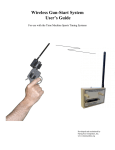
The Wireless Grip Switch System (WGSS) consists of two components: a Receiver Unit and one or more Wireless Grip
Switches. The Receiver unit plugs onto the multi-lane port connector of your Time Machine. Power for the Receiver unit is
supplied by the Time Machine through the multi-lane port and must be connected to the Time Machine before turning the
Time Machine’s power switch on in order to avoid causing a glitch on the Time Machine’s internal power supply. When
the Time Machine is powered up, the Receiver Unit turns on and is ready to receive signals from any Wireless Grip Switch
that it has been programmed to respond to.
Each Wireless Grip Switch transmits a unique ID code when triggered and it is transmitted over one of 10 different RF
channels. As long as each grip switch being used is transmitting over a different RF Channel, then they will not interfere
with each other if triggered at the same time (within 1/10 sec). If they are not triggered at the same time, then interference
will not be an issue. In order to avoid the possibility of interference, the user must be careful to insure that all of the
Wireless Grip Switches being used are operating on different RF Channels. The RF Channel is pre-programmed at the
factory and is displayed on the antenna. If you received a “set” of Wireless Grip Switches, then they will all have different
RF Channel settings. However, if you acquire additional Wireless Grip Switches, then you may have some with the same RF
Channel number. If this is the case, the RF Channel number can easily be changed by the user to eliminate any possible
interference problems. Please refer to section III on changing the RF Channel Number of a Wireless Grip Switch.
Wireless Grip Switches are assigned Lane/Chute numbers (and “start” functions) by programming the Receiver Unit. When
programmed, the Receiver Unit stores the grip switch ID codes in memory so that it can recognize a transmitted ID code and
then respond by asserting the associated Lane/Chute input to the Time Machine. The Receiver Unit is pre-programmed at the
factory, but it can very easily be reprogrammed by the user. Please refer to section II on Programming the Receiver unit.
The Receiver unit also extends all of the Multilane Port signals out to a 25-pin connector allowing you to use all of the
common accessories that connect to the Multilane Port.
3