1
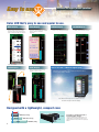
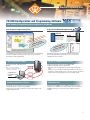
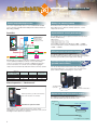
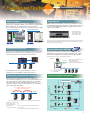
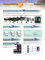
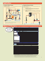
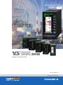
Single Loop Controller YS1000 Series Single Loop Controller Bulletin 01B08A02-01EN www.ys1700.com Adding value for the customer The Next Evolution of the YS Series Loop Controller 32 Years of Reliable Control! The new YS1000 Series of single-loop controllers is the successor to the Yokogawa YS100 and YS80 single loop controllers. The YS1000 Series offers improved connectivity with supervisory We are continuing to offer the YS1000, embodying the quality and reliability we have cultivated over the decades. systems and incorporates new, enhanced features that help operators work more efficiently. The YS1000 will work efficiently in petrochemical, chemical, power, pulp and paper, boiler and Incredibly easy to read display combustion control applications. TFT LCD makes it even easier to read. • Even wider viewing angle (at least 1.5 times wider than our previous model) • LED back light for brighter performance (at least 2.5 times brighter than our previous model) • Greater contrast (at least 20 times greater than our previous model) High reliability A YS beyond.... Dual CPU and manual control ensure high reliability. Improved maintainability Easy to upgrade With the YSS1000 setting software, you can convert your SLPC and YS170 programs with YS1700 programs. YS100 and YS80 compatible models also available. Compatible with 72 x 144 mm cutout FM/CSA certification planned YS1000™ Series is a core building block of Yokogawa's VigilantPlant solutions that promise to bring operational excellence. 2 Envision a plant... 3 Easy to use Functions that support process operations Color LCD that’s easy to see and easier to use. Meter display Event Display TREND Display ALARM Display Displays when events are occurring. messages can be displayed in English, Chinese, Japanese and other languages. Your selection of up to 4 analog inputs or outputs can be displayed as trends. Color LCD alarm display makes it easy to identify and review alarm activity. LOOP Display DUAL Display Uses a TFT LCD + LED back light display Loops color-coded for easy identification Ideal for 2-element control such as cascade or selector control Digital values displayed side-by-side with an intuitive analog meter makes the YS1000 the perfect replacement for YS80 or obsolete “moving coil” controllers. Single-loop controller Maintains good visibility, even on panels subject to direct morning and evening sunlight. Note: Avoid constant exposure to sunlight as this can shorten the lifespan of the LCD display. Designed with a lightweight, compact case YS1000 250 mm, 1.6 kg YS1000 YS100 320 mm, 3.4 kg YS100 YS80 4 480 mm, 6 kg YS80 Provides for greater freedom of instrumentation design Compact, lightweight design allows the use of smaller and less expensive panel. Moreover, it allows attachment to doors which was previously difficult. Reduction of engineering costs YS1000 Configuration and Programming Software Your Choice of Programming Style: Graphical or Text Based New Graphic Programming Tool Original Text Based Programming YS170 ion unct ing f r o t i on ule m mod e n i l onorts Supp city ks capa am 0 Bloc r g o 0 Pr rts 4 po Sup Backwards compatible with existing programs. Conversion software for existing YS170 user programs is available. le patib m o C SLPC Backwards compatible with existing programs. Conversion tool for importing programs from YS80 SLPC ROM is available. city capa teps. m a s r . Prog 1000 us YS170 orts previo Su5ptpimes of the 2. Programming is easier with our intuitive function block programming. The online module monitoring function allows you to confirm the performance while programming. Three connection modes Connection modes: USB, Ethernet or RS485 When connecting via RS485 or Ethernet, a communication option is required on the main unit. Configuration and Programming Software YSS1000 Backwards compatible with existing YS170 users programs. Increased programming capacity allows you to create more sophisitated control schemes. Full set of computation functions Ethernet communications Dedicated USB cable · Supports parameter setting for all YS1000 models · Support for YS1700 custom programming. - Calculations done using Engineering units and Floating point math. - Includes over one-hundred computation modules for exponents, logarithms, temperature/pressure correction, and other operations. - Function blocks (sub-programs) can be saved and reused. RS485 communication Password protection function Passwords can be assigned to user programs to prevent unauthorized access to proprietary programs. A password on the main unit prevents unexpected changes in the engineering parameters. Calibration tool Following the YSS1000’s online calibration instructions makes calibration easy. Calibration records and data can be saved on the YS1000, allowing you to load or print past calibration data as needed. 5 High reliability Improved process up time Control output backup function Battery free memory backup The control output backup function comes standard with YS1000 series controllers (YS1700 and YS1500) and the Manual Station for MV Setting (YS1360). Dual CPU Improved basic control performance The YS1000 series achieves higher performance than previous models (YS100 series). · I/O accuracy Display CPU's process at normal condition Display CPU Main CPU's process at normal condition Voltage input accuracy: ±0.2% ±0.1% Voltage output accuracy: ±0.3% ±0.1% Current output accuracy: ±1.0% ±0.2% Back-up process at fail Display signal Control Key operation Circuit D/A converter MV Output Circuit MV MV A/D converter PV · Internal data resolution of the I/O signal: 1/1000 1/10000 · Internal computation resolution of PID and other computations: 1/4096 1/65536 Main CPU PV MV operation Failure area Main CPU fail Display CPU fail tible AC/DC power supply resists powerline fluctuations. Compa The AC/DC (100V/24V) power supply powers the instrument to provide consistent performance.Also accepts DC power regardless of polarity (specify 220 V power supply when ordering). Hard Manual With dual-CPU construction (main CPU and display CPU), manual control capability and display continues even if an abnormality occurs on one of the CPUs. If controller self-diagnostics detects a control circuit failure, the controller can suspend analog/digital output, switch to manual mode and allow manual control by operator. Functions Nonvolatile memory is used for memory backup. Service life is improved because no batteries, backup capacitors, or other components are used. Controller online replacement function le patib m o (portable manual station) C Use the YS110 portable manual station when exchanging or performing maintenance on a controller. You can switch to the spare controller without interrupting the control output. All CPU and Control Circuit Control with “Hard manual” N/A Manual operation with front keys N/A Display for PV and SV Control algorithm stop stop stop Manual operation —“Hard manual” Front Panel Manual operation is possible even if all CPUs and control circuits are in a fail state. Hard manual operation wheel YS1700, YS1500 Controller YS110 Portable manual station Replace the display while retaining output. The display unit is replaced by Yokogawa service personnel. Recommended LCD replacement period: 8 years Brightness (%) 100.0 Slow to deteriorate New YS1000 Independent manual override is built into the control circuits, ensuring that control output can continue even when a control circuit including the CPU experiences a problem. Previous model 0.0 0 10 Year * Test data of our company 6 Powerful and Flexible Ethernet support System connectivity functions Expandable I/O The instrument can be easily connected to DAQWORX, SMARTDAC+ general-purpose SCADA, and OPC servers via Ethernet (Modbus/TCP). Measured data from the YS1000 can be recorded on the GX. Note: The GX requires the communication channel function option (/MC). Ethernet (Modbus/TCP) Additional I/O can be added by selecting the YS1700 basic model (with Expandable I/O). The total number of input/outputs points with the main unit and Expandable I/O are 8 analog inputs, 4 analog outputs, and 14 DI/DO. Ethernet (Modbus/TCP) • External AI: 3 inputs • External AO: 1 outputs • External DI: 4 points • External DO: 4 points GX10/GX20 Communication with PLC Note: An interface for the additional Expandable I/O cannot be added after delivery. If there is a possibility that extra input/outputs will be needed, we recommend that you start with the basic model (with expansion I/O). Communication with CENTUM Connections are enabled using the FA-M3’s UT link module and the RS485 communication function. No programming is necessary to exchange data between the instrument and the FA-M3. le patib Com As with previous models, communication with Yokogawa’s DCS (CENTUM) is supported. This is ideal for DCS backup in chemical plants and other applications requiring extreamly high reliability. Applicable Models: YS1700, YS1500, YS1350, and YS1360 FA-M3 CENTUM VP HIS Control bus FCS RS485 ALR121 Please specify the communication options /A31 (RS-485 communication) to directly communicate with the CENTUM. FCU RS485 YS1700 YS1700 Note: Direct communication with CENTUM. The YS1000 can also be connected to PLCs of various manufacturers via the Modbus communication protocol. Peer-to-peer communication function YS1700 YS1500 YS1350 YS1360 A sample of System Construction With peer-to-peer communication, up to 32 YS1700 can be connected interchangeably. Four of the connected instruments can each output 4 points of analog data and 16 points of status data. This makes data exchange and I/O sharing possible since all instruments under peer-to-peer communications can read all data (16 analog and 64 status data). I/O sharing Data sharing RS485 Field instruments This is optimal for multi-loop control as such with boiler instrumentation. Inter-lock system Upper system YS1700 YS1310 YS1700 Note: Does not support the YS100 series peer-to-peer communication network (YS-net). Maximum no. of connections No. of receiving units No. of transmitting units Transmitted data Communication interval : 32 : 32 :4 : 4 analog and 16 status data per transmitting YS1700 : 200 ms average (not synchronized to the control computation interval) YS1500 YS1350 YS1360 Field wiring Signal in the panel Communication 7 Compatibility Total cost reduction e atibl p m Co Cases and housing for replacing old models Indispensable for lasting, stable operations at the plant when replacing instrumentation. Case and housing are available for replacement of older-model SLCs by Yokogawa Electric Corp. (the EBS, I, EK, and HOMAC series) allowing you to exchange 2 YS100*1 YS80* YS1000 compatible type internal unit Case I,EBS*2 100line*2 Housing Housing EK*2 YS80*1 Housing Case instruments without modifying existing instrumentation panels. Moreover, front panel design with analog-like meters lets you update to new instruments without losing the familiarity of the old interface. Housing YS80 YS1000 *1: Compatibility is established by inserting the YS1000’s internal circuitry of the appropriate compatible type into the existing case. *2: Compatibility is established by inserting the entire YS1000 unit of the appropriate compatible type into the existing controller housing. Order the housing separately as needed. Self-tuning (STC) le patib m o C Setpoint filter (SVF) Simplifies tuning when starting up or changing the process unit under control. Before STC 60 40 40 Set-point change 60 40 At set-point change PV without SVF SV SV PV 20 0 At disturbance P = 160% I = 20sec. D = 0sec. SFA = 1.0 80 60 SV Can optimize tracking with changes in set-points. Also can maintain optimum responsiveness to disturbances. Before STC 100 P = 80% I = 20sec. D = 0sec. SFA = 1.0 80 SV·MV 80 SV·MV After STC 100 P = 89% I = 14sec. D = 2sec. SFA = 0.465 SV·MV 100 le patib m o C 0 1 PV 20 2 3 Time (min.) Flexible DI/DO 0 0 1 PV 20 2 3 Time (min.) 0 PV with SVF 0 1 2 Time (min.) SFA : SVF Parameter le patib m o C The YS1700/YS1500’s six DI/DO terminals can be used for both input and output. e atibl Programmable function key Comp With a user program, the program function key (PF key) on the instrument’s front panel can be used as an ON/OFF switch for self-tuning, or as a Start button for sequence operation. 3 optimum responsiveness to disturbances. Direct input function* optimize tracking with changes in set-points le patib m o C An optional signal conversion function can be added for 1 channel. Current, voltage pulse, thermocouples, RTDs, mV and potentiometers signals from differential pressure gauges, manometers, and flow meters can be connected directly to the controller. The direct input employs highly noise resistant, isolated inputs. TC mV TAGTAGTAG TAGTAGTA LOOP1 RTD PV ∞C SV ∞C H.MAN 100.00 123.45 –67.543 MV C A % 34.56 M ALARM–1 STC-ON STC ON Pulse 2 wire transmitter * Options available for suffix code “2”, “4”, “5” of “Type”. 8 0.00∞C C O Applications Automatic Boiler Control Residual Chlorine Control An appropriate distribution of control functionality enables safe and stable automatic boiler control. With the 2-loop control function, you can control hypochloric flow control and residual chlorine. Loop 1: Hypochloric flow control (Boiler master) Main steam pressure control Calculates hypochloric infusion from the flow, infusion rate, concentration, and specific gravity, and controls the flow. Feed water level control Fx PV1 FF Loop 2: Controls residual chlorine Cascade PRD control Control is achieved by receiving signals from a residual chlorine analyzer. The infusion rate from loop 1 is corrected by this control output. PV2 PV FF Steam Drum level SV Air flow control Main steam pressure X1 Main steam flow X2 Feed water SV Fuel flow control PV PV Y1 X3 Exhaust gas oxygen concentration control Fx SV Fuel oil Fuel oil flow Air flow Pump Oxygen Exhaust concentration gas Residual chlorine analyzer Air -Cascade Primary Direct (PRD) control: Enables stable level control when the boiler is started. -Cross limiting control calculation: Air and fuel flow are calculated so that air flow always exceeds fuel flow to prevent incomplete combustion and explosion. -Feedforward (FF) control: The main steam pressure and feed water level are controlled quickly in response to changes in the main steam flow. Flow Water Flow Models and Suffix Codes (See General Specification Sheets for the ordereing information in the detail.) Model Suffix codes can be used to select models with or without manual control. YS1700 YS1500 YS1310 YS1350 YS1360 Use Suffix code option code — — — — — — — — — — — Programmable Indicating controller Indicating controller Indicator with alarm Manual setter for SV setting Manual setter for MV setting — — — — — — — — — Without hard manual unit CE marking, IP54 Basic type CE marking, IP54 Basic type with expandable I/O *5 Compatible type for YS100 (with YS100 case) CE marking Compatible type for YS80 internal unit, Compatible type for EBS, I, EK and HOMAC Compatible type for YS80 (Compatible size for YS80 with YS100 terminal) Compatible type for 100 line (with YS100 terminal) 100VAC, 24VDC 220VAC mV input Thermocouple input RTD input Potentiometer input Isolator 2-wire transmitter input (isolated) 2-wire transmitter input (non-isolated) Frequency input Direct input with Fahrenheit temperature range function *7 RS-485 communication (PC-link, Modbus, YS protocol, Peer-to-peer) *4 *6 DCS-LCS communication *6 Ethernet communication (Modbus/TCP) *1 FM nonincendive approved (FM Class I, div 2) *1 (To be approved) CSA safety and nonincendive approved (Class I, Division 2) *2 (To be approved) -1 -2 0 1 2 3 4 5 Type 0 1 Power supply Direct input *3 /A01 /A02 /A03 /A04 /A05 /A06 /A07 /A08 /DF /A31 /A32 /A34 /FM /CSA Communication Certification Model Suffix code option code — — — — YSS1000 -0 0 Description In case of YS1700, YS1500 and YS1360: With hard manual unit In case of YS1310 and YS1350: Always “-1” Description Setting software for YS1000 series Always 0 Always 0 (with CD Media and proprietary cable) Accessories (sold separately) Product name SHUP standard housing SHUP long housing SHUP EK/HOMAC housing 100 Line pneumatic instrument replace housing 120 Ω terminating resistor 250 Ω shunt resistor Model SHUP-000 SHUP-100 SHUP-420 YS006 YS020 YS021 Remarks Available for YS1xx0-x3x (Replace for YS80 Series) Available for YS1xx0-x3x (Replace for I Series or EBS Series) Available for YS1xx0-x3x (Replace for EK or HOMAC Series) Available for YS1xx0-x5x (Replace for 100 Line pneumatic instrument) For RS-485 communication For a built-in 24 V transmitter power supply Option YS1700 User programming Expandable I/O Ethernet communication RS485 communication (PC-link, Modbus, YS protocol) RS485 communication (Peer-to-peer) DCS-LCS communication Direct input (*5) (*1) YS1500 N/A N/A (*1) N/A (*3) (*3) YS1310 N/A N/A (*1) N/A N/A (*3) YS1350 N/A N/A (*1) YS1360 N/A N/A (*1) N/A N/A (*3) (*3) *1 Can be added only for basic type (when selecting type “0” or “1”) *2 Can be added for basic type (when selecting type “0” or “1”) or compatible type for YS100 (when selecting type "2"). *3 Can be added only for compatible type for YS100 (when selecting type “2”, “4” and “5”). Multiple selections are not possible. *4 Cannot be combined with type “3” *5 For basic type with expandable I/O only (when selecting type “1”). An expansion I/O terminal (model: YS010) and expansion I/O cable (model: YS011) are included. *6 /A31 and /A32 cannot be specified together. Please specify the communication options /A31 (RS-485 communication) to directly communicate with the CENTUM CS3000/VP. Please specify the communication options /A32 (DCS-LCS communication) to communicate with the CENTUM through the SCIU. *7 This option can be combined only with option code /A02 or /A03.If option code /DF is specified, Fahrenheit temperature range can be available for direct input range in addition to Centigrade temperature range. In case of specifying Fahrenheit temperature range for direct input, option code /DF is required. When the direct input temperature range may be changed to Fahrenheit temperature range after shipment, also specify option code /DF. 9 YS1000 Series Line-up YS1700 YS1500 Programmable Indicating Controller A programmable controller in which control and computational functions are combined by the user with the YSS1000 programming tool. Each YS1700 can run two PID control calculations simultaneously and output the respective 4-20 mA output signals. The YS1700 can also be used as a multi-function controller without programming, in the same way as the Model YS1500. Controller mode Control type Control period Additional control function Extended control function Auxiliary control function Analog input Analog output Alarm function Digital signal Retransmission output Input computation Output computation Computation modules Program method Program capacity Security Communication Hardmanual Programmable, Multi-function mode (single-loop, cascade and auto-selector) Basic PID control (built-in nonlinear control function), proportional control (built-in nonlinear control function), sampling PI control, (built-in sampling PI control function), and batch PID control 0.05, 0.1 and 0.2 sec (programmable mode), 0.1 sec (multi-function mode) Adjustable setpoint filter (SVF), Self-tuning (STC), Non-linear PID control, PID control with reset bias function, output limiter, external cascade-control setpoint signal Input/output compensation, Variable gain, preset PID Feed-forward control, output tracking, preset MV output, PV/SV tracking, operation mode change, input filter, Square-root, 10-line-segment characterizer, ratio 1 to 5 V DC (5 channels or 8 channels with with expandable I/O) 4 to 20 mA (1or 2 channels), 1 to 5 V DC (2 channels or 3 channels with expandable I/O) High/low/high-high/low-low limits, deviation limit, and velocity alarm Six channels (each being common to both input and output) PV1, PV2, SV1, SV2, and other analog inputs Square-root with low signal cut off, 10-line-segment characterizer, first-order lag calculation, scaling of external cascade-control setpoint signal, feed-forward signal calculation Output high/low limiting Four arithmetic operations, square-root, absolute, selector, limiter, ten segmen characterizer, alarm, first-order lag, differentiation, dead time, velocity computations, moving average, timer, program setting, counter, pulse output, temperature/pressure compasations, power, logarithmic, logic computations, comparison, branching, switching, sub-program and register manipulation Function block or text (use YSS1000 configuration and programming software) 400 modules (function block), 1000 steps (text) Protection by password Modbus/TCP, RS-485 (modbus, peer-to-peer), and DCS-LCS Yes/No Indicating Controller Incorporates fundamental control functions required for PID control. Necessary functions can be selected in accordance with the user’s purpose. The available functions include those necessary for input signal processing, such as square root extraction and linear segment conversion, and feed-forward calculation. Cascade and autoselector control is also possible. Controller mode Control type single-loop, cascade and auto-selector Basic PID control (built-in nonlinear control function), proportional control (built-in nonlinear control function), sampling PI control, (built-in sampling PI control function) 0.1 sec Control period Extended control Adjustable setpoint filter (SVF), Self-tuning (STC), function Non-linear PID control, PID control with reset bias function, output limiter, external cascade-control setpoint signal Auxiliary control Feed-forward control, output tracking, preset MV output, function PV/SV tracking, operation mode change, input filter, Square-root, 10-line-segment characterizer, ratio 1 to 5 V DC (4 channels) Analog input 4 to 20 mA (1 channel) and 1 to 5 V DC (2 channels) Analog output High/low/high-high/low-low limits, deviation limit, and Alarm function velocity alarm Six channels (each being common to both input and Digital signal output) Retransmission output PV1, PV2, SV1, SV2, and other analog inputs Input computation Square-root with low signal cut off, 10-line-segment characterizer, first-order lag calculation, scaling of external cascade-control setpoint signal, feed-forward signal calculation Output computation Output high/low limiting Security Protection by password Communication Modbus/TCP, RS-485 (modbus), and DCS-LCS Hardmanual Yes/No YS1310 YS1350 YS1360 Indicating alarm monitor with two inputs for simultaneous monitoring of two loops. High-high, high, low, and low-low alarms can be detected for each of the two inputs, and logical ANDs or ORs of arbitrary alarms can be set. From among these, a total of six alarms can be assigned to alarm output contacts. This manual loader allows an operator to send a setpoint to a remote controller. Its operation mode is switched by the mode keys (C and M) or a status input. A status identification output is provided as standard. This manual loader allows an operator to interrupt a control signal to a final control device and manually control it's operation temporally. Its operation mode is switched by the mode keys (C and M) or a status input. A status identification output is provided as standard. When a YS1700, YS1500 or YS1360 requires maintenance, the YS110 Portable Manual Station can be used to output a 4 - 20 mA signal to the final control element. Simply swing up the front panel of the controller, connect this unit to the controller, and replace the internal assembly while keeping the existing manipulated output active. Analog input Digital signal Analog input Analog output Digital signal Analog input Analog output Input signal Manipulation signal Input/manipulation signal meters Indicator with Alarm Alarm functions Input computation Security Trend display Communication 10 1 to 5 V DC (2 channels) Six outputs(with one for digital input as backlight off) and one FAIL contact High/low/high-high/low-low limits Square-root with low signal cut off, first-order lag calculation Protection by password PV1, PV2 Modbus/TCP, RS-485 (modbus), and DCS-LCS Manual Setter for SV Setting Alarm functions Input computation Security Trend display Communication 1 to 5 V DC (2 channels) 1 to 5 V DC (1 channel) Two input, three outputs and one FAIL contact High/low limits Square-root with low signal cut off Protection by password PV1, SV1, MV1, and other analog inputs Max. 4 points Modbus/TCP, RS-485 (modbus), and DCS-LCS YS110 Manual Setter for MV Setting 1 to 5 V DC (2 channels) 4 to 20 mA (1 channel) and 1 to 5 V DC (1 channel) Two input, three outputs Digital signal and one FAIL contact High/low limits Alarm functions Input computation Square-root with low signal cut off Security Protection by password Trend display PV1, SV1, MV1, and other analog inputs Max. 4 points Communication Modbus/TCP, RS-485 (modbus), and DCS-LCS Hardmanual Yes/No Portable Manual Station Output manipulation I/O connection Models to be backed up 1 to 5 V DC (1 channel) 4 to 20 mA DC (1 channel) Moving-coil method Range: 0 to 100% Scaling: 20 equal divisions Manual using the front-panel dials I/Os are coupled with the connector on the case using a dedicated cable. YS1700, YS1500, YS1360 Terminal Block YS1700/YS1500 Terminal Arrangements Terminal No. 1 2 3 4 5 6 7 8 9 10 11 12 YS1700 Programmable mode Analog input 1 (1-5V DC) Analog input 2 (1-5V DC) Analog input 3 (1-5V DC) Analog input 4 (1-5V DC) Analog input 5 (1-5V DC) Fail output YS1310/YS1350/YS1360 Terminal Arrangements YS1700/YS1500 Single-loop mode PV (1-5V DC) Cascade set point input (1-5V DC) Tracking input (1-5V DC) Feedforward input (1-5V DC) Direct input signal output (1-5V DC) (*1) Fail output Cascade mode PV1 (1-5V DC) Cascade set point input (1-5V DC) PV2 (1-5V DC) Feedforward input (1-5V DC) Direct input signal output (1-5V DC) (*1) Fail output Selector mode Terminal No. PV1 1 (1-5V DC) 2 Cascade set point input 1 3 (1-5V DC) 4 PV2 5 (1-5V DC) 6 Cascade set point input 2 7 (1-5V DC) 8 Direct input signal 9 output (1-5V DC) (*1) 10 Fail output 11 12 YS1310 YS1350 PV1 Direct input signal (1-5V DC) PV2 (1-5V DC) output (1-5V DC) (*1) Fail output YS1360 PV1 Direct input signal (1-5V DC) Cascade set point input (1-5V DC) output (1-5V DC) (*1) Fail output PV1 Direct input signal (1-5V DC) Cascade input (1-5V DC) output (1-5V DC) (*1) Fail output 13 Transmitter Power supply (24V DC) Transmitter Power supply (24V DC) Transmitter Power supply (24V DC) Transmitter Power supply (24V DC) 13 Transmitter Power supply (24V DC) Transmitter Power supply (24V DC) Transmitter Power supply (24V DC) 14 Communication SG Communication SG Communication SG Communication SG 14 Communication SG Communication SG 15 Communication SDA () Communication SDA () Communication SDA () Communication SDA () 15 Communication SDA () Communication SDA () Communication SDA () 16 Communication SDB () Communication SDB () Communication SDB () Communication SDB () 16 Communication SDB () Communication SDB () Communication SDB () Communication SG 17 Communication RDA ()or LCS () Communication RDA ()or LCS () Communication RDA ()or LCS () Communication RDA ()or LCS () 17 Communication RDA () Communication RDA ()or LCS () Communication RDA ()or LCS () 18 Communication RDB ()or LCS () Communication RDB ()or LCS () Communication RDB ()or LCS () Communication RDB ()or LCS () 18 Communication RDB () Communication RDB ()or LCS () Communication RDB ()or LCS () 19 20 Direct input (*1) Direct input (*1) Direct input (*1) 19 Direct input (*1) 21 N G Ground (GND) 23 24 25 26 27 28 29 30 31 32 33 34 35 36 37 38 39 L Direct input (*1) Direct input (*1) Direct input (*1) 21 22 20 Analog output 1 (420mA DC) Analog output 2 (1-5V DC) Analog output 3 (420mA DC/1-5V DC) Digital output 1 or Digital input 6 Digital output 2 or Digital input 5 Digital output 3 or Digital input 4 Digital output 4 or Digital input 3 Digital output 5 or Digital input 2 Digital output 6 or Digital input 1 Power supply MV1 (420mA DC) MV2 (1-5V DC) SV (1-5V DC) PV1 high limit alarm output PV1 low limit alarm output Deviation alarm output C/A·M status output C·A/M status output Action mode switching input Power supply Ground (GND) MV1 (420mA DC) MV2 (1-5V DC) SV (1-5V DC) First loop alarm output Second loop alarm output O/C status output C/A·M status output C·A/M status output Action mode switching input Power supply Ground (GND) MV1 22 (420mA DC) 23 MV2 24 (1-5V DC) 25 SV 26 (1-5V DC) 27 First loop alarm output Second loop alarm output L/R status output C/A·M status output C·A/M status output N G Ground (GND) 28 29 30 31 32 33 34 35 36 37 Action mode switching 38 input 39 Power supply Ground (GND) L Alarm output 1 Alarm output 2 SV PV1 high limit alarm (1-5V DC) output PV1 low limit alarm output Alarm output 3 Alarm output 4 Alarm output 5 Alarm output 6 or Degital input 1 Power supply C/M status output Input for LCD backlight off Action mode switching input Power supply Ground (GND) MV1 PV1 high limit alarm (420mA DC) MV2 (1-5V DC) output PV1 low limit alarm output C/M status output Input for LCD backlight off Action mode switching input Power supply Ground (GND) *1: Only applicable for YS100 compatible terminal type (“2” “4” “5”) YS1000 Series (Basic Type) Terminal Block YS010 Expandable I/O Terminal Arrangements Terminal number 1 2 3 4 5 6 7 8 9 10 11 12 Our product names or brand names mentioned in this manual are the trademarks or registered trademarks of YOKOGAWA Electric Corporation (hereinafter referred to as YOKOGAWA). Microsoft, MS-DOS, and Windows are either registered trademarks or trademarks of Microsoft Corporation in the United States and/or other countries. Ethernet is a registered trademark of XEROX Corporation. We do not use the TM or ® mark to indicate these trademarks or registered trademarks in this user’s manual. All other product names mentioned in this user’s manual are trademarks or registered trademarks of their respective companies. 1 2 3 4 5 6 7 8 9 10 11 12 13 14 15 16 17 18 19 20 21 22 23 24 Expandable I/O Terminal Analog input 6 Analog input 7 Digital input 7 Digital input 8 Digital input 9 Digital input 10 Terminal number 13 14 15 16 17 18 19 20 21 22 23 24 Expandable I/O Terminal Analog input 8 Analog output 4 (1 to 5VDC) Digital output 7 Digital output 8 Digital output 9 Digital output 10 11 67 Main Unit Dimensions (YS1000 Basic Type) (YS1000 Basic Type with Expandable I/O) 69.8 Dimensions 56 Note 1 When swung up 60 Instrument panel thickness: 2.3 to 25 mm Expandable I/O cable (YS1700 with Expandable I/O) Clamp bracket 60 13 24.6 250 Clamp bracket 162.4 144 136.4 R6 0 M IN 13 72 132 MIN Note 2 6 72 Weight: Main unit 1.6 kg + Expandable I/O Cable 320 g Note 1: If a nameplate, etc. is installed within 60 mm above the instrument, the height of the nameplate, etc. must be 30 mm or less from the panel surface. Note 2: When installing the expandable I/O cable, secure the wiring space of at least 60 mm for a minimum curvature radius of the cable in addition to the mountiing bracket space of 72 mm from the terminal cover face of the main unit. Expandable I/O Terminal Dimensions Panel Cutout Width 176 167 68 (For side-by-side mounting) +0.7 0 L +1 0 Expandable I/O Cable Dimensions R1.25-4 137 220 or more Weight: 260 g 220 or more 7 31.2 +2 0 2- n4 33.5 (when mounted on DIN rail) +2 0 M4xL8 137 11 .5 9 4 5 29.75 50 60 (For single mounting) Ground wiring: 1.25 mm2, green Length:500 ± 50 mm Panel Cutout Width for Side-by-side Mounting Number of instruments to be mounted L (mm) 2 3 4 5 6 7 8 9 10 11 12 13 14 140 212 284 356 428 500 572 644 716 788 860 932 1004 (70) Third angle projection Unit: mm General tolerance: ±(value of tolerance class IT18 based on JIS B 0401-1998)/2 (95) 3000 ± 50 mm (40) Weight: 320 g YOKOGAWA CORPORATION OF AMERICA 2 Dart Road, Newnan, Georgia 30265, U.S.A. Phone: 800-258-2552, Fax: (1)-770-254-0928 YOKOGAWA EUROPE B.V. Euroweg 2, 3825 HD Amersfoort, THE NETHERLANDS Phone: (31)-88-4641000, Fax: (31)-88-4641111 YOKOGAWA ENGINEERING ASIA PTE. LTD. 5 Bedok South Road, Singapore 469270 Phone: (65)-62419933, Fax: (65)-62412606 YOKOGAWA ELECTRIC CORPORATION Control Instruments Business Division 2-9-32 Nakacho, Musashino-shi, Tokyo, 180-8750 Japan Phone: (81)-422-52-7179, Fax: (81)-422-52-6973 E-mail: [email protected] Subject to change without notice. All Rights Reserved, Copyright c 2014, Yokogawa Electric Corporation. *1: When attaching a nameplate or the like to the panel within 60 mm above this instrument, ensure that its thickness is less than 30 mm. *2: To ensure adequate ventilation, allow space of at least 100 mm above and below the panel. *3: Front display of YS1700 and YS1500 are shown, and they are slightly different from that of YS130 (keytop and front plate and the like) . Represented by : Vig-RM-6E Sign up for our free e-mail newsletter www.yokogawa.com/ns/ Printed in Japan, 405(KP) [Ed : 01/b]