1
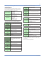
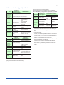
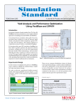
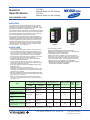
General Specifications YS1350 Manual Setter for SV Setting YS1360 Manual Setter for MV Setting GS 01B08E02-01EN l tiona Func ment nce Enha nGENERAL The YS1350 is a manual setter that allows for manually outputting setting signals to controllers and the like. The YS1360 is a manual setter that allows for manually outputting operation signals to operation terminals. The YS1350 and YS1360 include as standard an operation mode selector switch [cascade (C) and manual (M)], status input-based operation mode selector function, and operation mode discrimination status output function. The YS1350 and YS1360 offer high reliability thanks to Yokogawa’s proprietary technology, user friendliness, and expandability. The basic type conforming to the DIN short case size contributes to space saving for mounting, and complies with standards (CE, FM*, and CSA*). For easy replacement of earlier models requiring the same panel cutout dimensions and depth as those of earlier models are also offered. *: To be approved. YS1350 YS1360 nFEATURES ▪A full-dot, TFT LCD Clear visibility of the display screen is ensured even in direct sunlight in the early morning and late afternoon. The user can freely access a desired operation screen from meter, trend, bar graph, alarm, and event displays. All parameters can be set via the front panel display. ▪The parameters can all be set by operation on the front panel (no need to draw out the internal unit). ▪Parameters can also be set using YSS1000 Setting Software available separately. ▪Can be driven by either an AC (100 V) or DC (24 V) power supply. (Must be specified upon ordering if using a 220–240 V DC power supply.) ▪ Dust- and splash-proof IP54 compatible faceplate (for basic type only) ▪ Depth 250 mm (only for the basic type) ▪ No battery or capacitor is used for memory backup. No maintenance is required because batteries and backup capacitors are not used. ▪ CE mark (for basic types and YS100-compatible type only) ▪ FM non-incentive explosion protection (optional for basic types only) (To be approved) ▪ CSA non-incentive explosion protection (optional for basic type, compatible type for YS100 (with YS100 case)) ▪ Communication (option) Ethernet (Modbus/TCP) (for basic types only) RS485 (PC Link, Modbus, YS protocol, unavailable for YS80 internal unit-compatible type) ▪ Compatibility with the YS100 series Setting and control operations can be done with the same feel. In the case of the basic type, terminal-to-terminal pitches differ but the signal-to-terminal arrangement is almost the same. The following functions are included to ensure compatibility with the SMST. ▪ Meter Display was added to the Operation Display. ▪ Housing for replacement purposes (SHUP-000 separately available) (To be approved) Type Basic type Model and Suffix Codes ( ¨ : Depending on specifications) YS1350 YS1360 Analog Inputs (*1) 1-5V Direct Input (*2) Analog Outputs YS1350/YS1360 Digital Outputs Digital Inputs YS1350-10x YS1360-x0x 2 - 1/2 3 2 YS1350-12x Basic type with expandable I/O (/A ¨ (*1)) YS1360-x2x (/A ¨ (*1)) 2 (1) (1) 1/2 3 2 Compatible type for YS100 Compatible type for YS80 internal unit Compatible type for EBS and I series YS1350-13x YS1360-x3x 2 - 1/2 3 2 Compatible type for EK and HOMAC YS1350-14x (/A ¨ (*1)) YS1360-x4x (/A ¨ (*1)) 2 (1) (1) 1/2 3 2 (1) 1/2 3 2 Compatible type for YS80 YS1350-15x YS1360-x5x (Compatible size for YS80 with 2 (1) (/A ¨ (*1)) (/A ¨ (*1)) YS100 terminal) *1: The point counts shown in parenthesis are those when direct input is specified. *2: One of the two analog inputs can be used as direct input (option/A ¨ : ¨ = 01 to 08) Yokogawa Electric Corporation 2-9-32, Nakacho, Musashino-shi, Tokyo, 180-8750 Japan GS 01B08E01-01EN ©Copyright Jun. 2014 (YK) 1st Edition Jun 13,2014 (YK) 2 nDisplay and Setting Functions •Tag Number and Digital Value Displays ● Display functions Display characters for tag numbers Display digits of tag numbers Display digits of PV and SV digital indications Display digits of MV digital indications (1) Display specification The screen is divided into Operation Display, Tuning Display, and Engineering Display groups, and functions can be set on the setting display for each function. Operation displays Tuning displays Engineering LOOP displays TREND displays ALARM displays METER displays FAIL display (when a failure occurs) Setting display Input/output data display Function settings Input specification settings Password setting Operation display settings LCD settings Communication settings (2) Operation Displays •Bar Graph Displays (in LOOP and DUAL displays) Scale divisions Digits of scale markings Display position of scale markings Units PV bar graph resolution SV pointer resolution Alarm setting pointer resolution MV bar graph resolution Up to 20 Up to 7 digits (including decimal point and sign) At 0% and100% positions Up to 7 alphanumeric characters 0.5% 0.5% (only for YS1350) 0.5% 1.25% (only for YS1350) PV overflow display Above 100% PV underflow display Below 0% •Meter Displays (in METER displays) Scale markings Up to 12 Up to 7 (including decimal point and sign) Up to 6 (including decimal point and sign) ▪ Trend display specification Trend display types PV1 and SV1 trends can be displayed and Trend 1 Display hidden. PV1 and SV1 scaling can be displayed. Four arbitrary values for PV1, SV1, PV2, SV2, X1, and X2 can be selected and displayed on Trend 3 Display a single display. PV scaling can be displayed. Trend display time span Trend display time span 1.5 minutes, 7.5 minutes, 15 minutes, 45 minutes, 1.5 hours, 7.5 hours, 15 hours, and 45 hours ▪ Event display specification Function Cancel and redisplay When an event occurs, a popup window appears on Operation Display. Preset messages appear in the popup window. The event display can be closed by pressing the SHIFT key for three seconds and the messages can be redisplayed in the ALARM display. Number of settable events Up to 5 Setting software (available separately) The YSS1000 (Setting software for the YS1000) is used. Display details and event flags are set with the YSS1000’s event display function. Display during Failure Scale divisions Scale graduation Alphanumeric characters Automatic setting based on upper and lower scale limits (reading factor can be modified). The display is automatically switched to the FAIL display upon a failure. Refer to the functional specification. Reading factor Digits of scale markings Display position of scale markings Units PV pointer resolution SV pointer resolution Alarm setting pointer resolution MV pointer resolution Up to 4 digits (including decimal point and sign) At 0% and 100% positions Up to 7 alphanumeric characters 0.5% 0.5% (only for YS1350) 0.5% 1.25% (only for YS1360) All Rights Reserved. Copyright © 2014, Yokogawa Electric Corporation GS 01B08E02-01EN Jun.01,2014-00 3 ● Display section names (1) Front panel section names YS1360 front panel YS1350 front panel YS1360 YS1350 1 LCD display unit (color LCD): 120 x 320 dots *1 1 LCD display unit (color LCD): 120 x 320 dots *1 2 FAIL lamp (LED: red) 2 FAIL lamp (LED: red) 3 ALM lamp (LED: yellow) 3 ALM lamp (LED: yellow) 4 C mode key (LED: green), M mode key (LED: yellow) 4 C mode key (LED: green), M mode key (LED: yellow) 5 MV decrease key 5 SV increase key 6 MV increase key 6 SV decrease key 7 Page key 8 Fast-change key/SHIFT key 9 Tag label (recommended placement position) 7 Page key 8 SHIFT key 9 Tag label (recommended placement position) *1: The backlight brightness can be adjusted, and the backlight can be turned off. (2) Swing-up internal panel section names Front Panel (YS1360 only) (YS1360 only) (YS1360 only) (YS1360 only) Item Name ● Control output backup (For suffix code -1xx) (For YS1360 only) The hard manual wheel behind the front panel enables manual operations. Output balancing before switching to/from hard manual is possible. Note: Connecting the YS110 standby manual station enables the internal unit to be replaced without interrupting the 4 to 20 mA DC control output (Y1). (Replacement of the internal unit, however, should be performed by a Yokogawa authorized service person.) Remark 1 Connector for PC connection (PROGRAMMER) A communication cable connector to download and upload parameters set with YSS1000 Setting Software 2 Internal unit’s release bar 3 Internal unit’s fixing screws Do not draw out the internal unit. If you need to draw out the internal unit, ask our sales representative or service office. 4 Connector for the YS110 Standby Manual Station Can be used only for YS1360. 5 Hard manual operation wheel 6 MV balance lamp 7 Hard manual selector switch 8 LED and switch for repair Can be used only for YS1360. An operation wheel for output manipulation. Can be used only for YS1360. Lights up when the manipulated output value and the hard manual output value match. Can be used only for YS1360. Used to switch over the output (MV) to the level set by the hard manual operation wheel. Contact us for repair. All Rights Reserved. Copyright © 2014, Yokogawa Electric Corporation GS 01B08E02-01EN Jun.01,2014-00 4 nFunctional Specification ▪ Response to Power Recovery ● Alarm function Name Setting range High limit alarm setpoint for PV -6.3 to 106.3% Low limit alarm setpoint for PV -6.3 to 106.3% Alarm hysteresis 0.1 to 20.0% Remark Set in engineering units ▪ Alarm output: 2 points ▪ Contact status during alarm: Close or open as selected by the user. ▪ Contact status during power failure: Open. Name Alarm setting pointer display Service High limit alarm setpoint for PV Low limit alarm setpoint for PV ALM lamp Alarm Indications Indication When Alarm Setpoint is Set or When Alarm Has Occurred LOOP Display METER Display Yellow pointer Yellow pointer Lights up in yellow Alarm occurAlarm indication on rence indication LOOP display Alarm name Display on ALARM display Inversion and Tag number in- alternating display version display of tag numbers in all displays Active display Remark ― ― ― Enabled and disabled by a parameter. Alarm type to cause the acChange of PV bar and tive display is its background colors to be set by a parameter. ● Input signal computation function Square root computation Setting Range PV square root computation OFF: square root computation disabled ON: square root computation enabled PV square root computation low signal cut off point setting value 0.0 to 100.0% ● Output signal computation function Name Output limiter function for MV Setting Range -6.3 to 106.3% -6.3 to 106.3% ● Input and output computation period 100 ms ● Power failure and power return operation Operation starts under the conditions of start mode set with the parameters. Parameters are stored in the nonvolatile memory. ▪ Return mode Select from the following return modes. Start Mode Duration of Failure Less than approx. 2 s Approx. 2 s or longer AUT mode M-COLD mode C-COLD mode COLD mode Start Mode (START) M-COLD C-COLD start start Remains the same as C and M status M mode before power failure.. Manipulated output (MV) (YS1360) Setting value (SV) (YS1350) Parameter First-order lag computation Process alarm and system alarm Analog output terminal Y1 (YS1360) Remains the same as before power failure. C mode COLD start Remains the same as before power failure. -6.3% Remains the same as before power failure. Remains the same as before power failure. Continuously Initialized performed. Continues without OFF change Continues without -20% change Continues Analog output without -6.3% terminal Y2 change Continues DO01 to DO02, without OFF DO04 change ● Self-diagnosis function (1) FAIL Diagnosis Content Clock stop Main CPU abnormal Display CPU abnormal Name High limit output limiter Low limit output limiter HOT start Hot start Hot start Hot start M-cold start Hot start C-cold start Hot start Cold start All Rights Reserved. Copyright © 2014, Yokogawa Electric Corporation A/D conversion unit abnormal RAM abnormal System ROM abnormal Nonvolatile memory abnormal When a failure occurs: FAIL lamp lights up. FAIL contact output open (Open when a power failure occurs) (2) Alarm Diagnosis Content System alarm Process alarm When an alarm is generated: ALM lamp lights up. The alarm cause is displayed on the screen. Active display (only when the function is set to ON) = When a process alarm is generated, the color of the PV bar on LOOP Display changes. Tag blinking display (only when the function is set to ON) = When an alarm lamp lights up, the color of the tag is changed and blinking alternately. ● Screen display when a failure occurs When a failure occurs, the screen changes to FAIL Display. When the main CPU fails, FAIL Display is displayed using the display CPU, and output can also be performed in MAN mode. When the display CPU fails, FAIL Display is displayed using the main CPU, and output can also be performed in MAN mode. ● Security Password-based parameter protection function GS 01B08E02-01EN Jun.01,2014-00 5 nHardware Specification ● Input and output signal specification Analog input signal Specification 1 to 5 VDC 2 points, PV input and cascade input Input resistance 1 MΩ or more Direct input (*1) One of the above 2 points (PV input) possible (option) *1: Any one of mV, thermocouple, resistance temperature detector, potentiometer, 2-wire transmitter, input isolator, or frequency input. Analog output signal YS1350 4 to 20 mA Load resistance 1 to 5 VDC Load resistance None None 1 point 2 kΩ or more YS1360 1 point 0 to 750 Ω 1 point 2kΩ or more Digital input Specification Digital input Input signal 2 points (operation mode switching input, LCD backlight auto-off input ON OFF Close Open Resistance 200 Ω Resistance 100 kΩ or less or more Low High In case of voltage Input voltage –0.5 Input voltage +4.5 contract (*2) to 1 VDC to 30VDC *2: Input contact rating: 5VDC, 20 mA or more Minimum pulse width: 120 ms *3: The no-voltage contact and voltage contact share the same terminal. In case of no-voltage contact (*2) (*3) Digital output ● Reference performance Reference operating conditions Ambient temperature: 23°C ±2°C, relative humidity: 50% ±10% However, the power supply voltage shall be as follows. 24 VDC ±10% or 100 VAC ±10%, 50/60 Hz 135 VDC ±10% or 220 VAC ±10%, 50/60 Hz Item 1 to 5 V input signal ±0.1% of the span (*1) Direct input ±0.5% or ±(2 x | direct input card accuracy | + 0.1%) (*1) Allowable input voltage 1 to 5 V signal Direct input signal (distributor) 1 minute (time required to meet the tolerance after the power is turned on), 3 minutes in the case of direct input. Input resistance 1MΩ (1 to 5 V input) Current consumption and power consumption Insulation resistance Withstanding voltage Specification 25 to 25.5 VDC Load 30 mA or less (60 mA or less when direct input is not used) 80 mA ±10 mA The computation circuit is not affected by a short circuit. Not isolated from the computation circuit. 1 to 5 V conversion resistance (250 Ω) shall be supplied externally. Short-circuit protection Other ● Isolation of signals from each other Specification Not isolated from the computation circuit. Signals are not isolated from each other. The negative wire is shared. Isolated from other input and output signals. Except for a 2-wire transmitter (not isolated), the input signal and computation circuit are Direct input isolated. Isolated from the power supply circuit, and other input and output signals. Digital input and output Isolated from the computation circuit. Signals are also isolated from each other. Isosignal lated from other input and output signals. FAIL signal Communication Isolated from the computation circuit. Isolated from other input and output signals. Power supply Analog input and output signal Grounding All Rights Reserved. Copyright © 2014, Yokogawa Electric Corporation +40 mA DC Warm-up time ● Transmitter power supply Output voltage ±30 VDC Direct input signal (mV, TC) -0.5 to 4 VDC Specification 3 points (C/M status output, high limit Digital output alarm output, low limit alarm output) Transistor contact Rated 30VDC/200mA (resistance load) FAIL output (*4) 1 point Rating: 30 V DC, 200 mA (resistance load) Transistor contacts *4: FAIL contact output is in the off state when the power is OFF and a failure occurs. (In normal time: on state) Operation is a NC operation. Specification Input and output conversion accuracy rating 100 VAC and 24 VDC common power supply 750 mA (20 to 132 VDC) 30 VA (80 to 138 VAC) 220 VAC power supply 110 mA (120 to 340 VDC) 30 VA (138 to 264 VAC) 100 MΩ or more (at DC 500 V) between input and output terminal and ground terminal, and between power supply terminal and ground terminal 1000 VAC for one minute (for suffix Between input/ codes -x0x or -x2x) output terminal and 500 VAC for one minute ground terminal (for suffix codes -x3x, -x4x, -x5x) Between power supply terminal (L, N) and (all I/O terminal and ground terminal) 3000 VAC for one minute (for suffix codes -x0x or -x2x) Between power 1500 VAC for one supply terminal (L,N) minute and ground terminal LCD display unit 8 years replacement cycle *1: Measurement classification in accordance with IEC/ EN61010-1, IEC/EN61010-2-030, and CAN/CSA-C22.2 No.61010-1, CAN/CSA-C22.2 No. 61010-2-030: O (other) ● Influence of operating conditions Item Specification Influence of changes in |Accuracy| (in the range of power supply power supply rating) Influence of input lead 0.13% (per 1 kΩ) resistance |Accuracy|/5 Influence of load 2 kΩ to ∞, 1 to 5 V output resistance 0 to 750 Ω, 4 to 20 mA Common mode noise 83 dB (1 to 5 V input) 50/60 Hz rejection ratio Series mode noise 46 dB (1 to 5 V input) 50/60 Hz rejection ratio Influence of magnetic field |Accuracy|/5 (400 A/m, 50/60 Hz or DC) Influence of ambient temperature |Accuracy| (per 10°C in the range of 0 to 50°C) Influence of ambient humidity |Accuracy| (50 to 93% RH, 40°C) GS 01B08E02-01EN Jun.01,2014-00 6 nCommunication Signal Specification Item Electrical specification Transmission control methods Baud rate Programmer Communication (Used for YSS1000) RS-232C compliant RS-485 Communication EIA RS-485 compliant Asynchronous, no Asynchronous, no proceprocedure, half-duplex dure, half-duplex - 1200, 2400, 4800, 9600, 19200, 38400 bps PC link PC link with SUM Modbus ASCII Modbus RTU YS protocol Back panel screw terminal (5 terminals and 1 ground terminal) Protocol Dedicated protocol Connection Dedicated front panel connector Number of connection modules 1 module Up to 31 modules/port Applicable cable Dedicated cable A1053UR(USBRS232C conversion cable) Shielded twisted pair wire Wire size: 0.5 to 1.25 mm2 (AWG No. 20 to 16) Cable length About 2.7 m Up to 1200 m (1.25 mm2) DCS-LCS Communication Item Ethernet Communication Electrical specification Transmission control methods Yokogawa’s proprietary IEEE802.3 compliantone 10BASE-T/100BASE-TX Back panel screw terminal (2 terminals) CSMA/CD Baud rate - 10 Mbps, 100 Mbps Protocol - Modbus/TCP Connection - Number of connection modules 8 modules/LCS card4 modules/SCIU card Applicable cable Dedicated shielded twisted pair wire (Model: SCCD) 10BASE-T/100BASE-TX cable Cable length Up to 100 m 100 m (*2) ● Communication functions Communication with the host systems Communication with host systems such as Yokogawa’s DCS (CENTUM) or Yokogawa’s PLC (FA-MA3) is possible. Destination Link device in host system YS1350/1360 communication functions Option CENTUM CS3000 or VP ALR121 (direct communication) FA-M3 UT link module PLC or PC from other vendors Device with RS485 communication functions Device with Eth- Ethernet ernet communi- communication cation functions (/A34) Protocol YS protocol RS-485 communication (/A31) PC link Modbus Modbus/TCP ▪Communication items Measured values can be read out and configuration parameters can be read out and written. Data setting can be enabled and disabled through the use of communication. ▪Computer modes: In addition to the previously mentioned normal operation modes, there are two operation modes for control by an host system. In DDC mode, the control output MV is directly manipulated by the host system (for YS1360 only). In SPC mode, the control setpoint SV is manipulated by the host system (for YS1350 only). ▪Backup mode after communication fault: The mode into which the controller should fall when communication with the host system has continuously been lost for a preset time period, the M mode is activated. Back panel RJ45 connector Up to 4-tier cascade stack(10BASE-T)Up to 2-tier stack(100BASE-TX) (*1) Number of connections: 2 *1: Number of cascade connected hubs *2: Maximum segment length (length between hub and YS1350/YS1360) All Rights Reserved. Copyright © 2014, Yokogawa Electric Corporation GS 01B08E02-01EN Jun.01,2014-00 7 nDirect Input Specification Item mV input Optional code /A01 Input signal DC potential difference -50 to +150 mV Thermocouple Input /A02 JIS and ANSI standards, thermocouple types K, T, J, E, B, R, S IEC and ANSI standards, type N 10 to 63 mV (thermoelectric power equivalent) Within the smaller value out of either 3 times the span or ±25 mV Measurement 10 to 100 mVDC range span Within the smaller value Measurement out of either 3 times the range zero span or elevation ±50 mV Measurement Can be changed on Engineering Display. range Input resist1 MΩ (3 kΩ in the event of a power failure) ance External input 500 Ω or less resistance Allowable input voltage -0.5 to 4 VDC and current Input lineariNo Yes zation 1 to 5 V output The larger value out of eiWithin ±0.2% of the conversion acther ±0.2% of the span or span curacy rating input equivalent ±20 µV Reference junction Within ±1°C (*1) compensation error *1: Reference junction temperature compensation is not performed for type B. With the exception of type B, when the measured temperature is less than 0°C, the above value is to be multiplied by the following factor (K). K = (thermoelectric power per 1°C around 0°C)/ (thermoelectric power per 1°C for the measured temperature) Item Resistance Temperature Detector Input Optional code /A03 Potentiometer Input /A04 Pt 100 (IPTS-68:JIS’89), JPt100 (JIS’89) Pt100 (ITS-90: JIS’97), Input signal Potentiometer, 3-wire Pt50(JIS’81) 3-wire Measurement current: 1mA Total resistance: 100 to Measurement 10 to 650°C (Pt100) 2000 Ω range span 10 to 500°C (JPt100) Span: 80 to 2000 Ω Measurement Within 50% of total range zero Within 5 times the span resistance elevation Measurement Can be changed on Engineering Display. range External input 10 Ω or less per wire (*2) 10 Ω or less per wire resistance Input lineariYes No zation 1 to 5 V output The larger value out of Within ±0.2% of the conversion ac- either ±0.2% of the span span curacy rating or ±0.2°C *2: The value shall be equal or less than the smaller value out of 10 Ω per wire or (measurement temperature span) × 0.4 Ω. All Rights Reserved. Copyright © 2014, Yokogawa Electric Corporation Item Input Isolator 2-wire Transmitter Input and 2-wire Transmitter Input (Input Not Isolated) Optional code /A05 /A06, /A07 Input signal 4 to 20 mADC signal from the 2-wire transmitter (power is supplied to the transmitter) 1 to 5 VDC 1 MΩ (100 kΩ in the event of a 250 Ω power failure) RL = within (20-miniExternal input mum transmitter operatresistance ing voltage)/(0.02 A (Ω)) Allowable input voltage ±30 VDC 40 mADC and current Input lineariNo No zation 1 to 5 V output converWithin 0.2% of the span sion accuracy rating Input resistance Item Frequency Input Optional code /A08 Input signal 2-wire: contact, voltage pulse, current pulse (power can also be supplied to the transmitter) 3-wire: power supply type voltage pulse Input frequency 0 to 10 kHz (0 to 10 Hz when the input filter is set to ON.) 100% frequency 0.1 to 10 kHz (0.1 to 10 Hz when the input filter is set to ON.) Zero elevation 0 to 50% can be set for 100% input frequency. Measurement Can be changed on Engineering Display range Low level Setting range: 0.01 Hz (and 1% of maximum input cut off frequency) to 100% input frequency. point ON: 60 µs Minimum OFF: 60 µs (input frequency 0 to 6 kHz) input pulse ON: 30 µs width OFF: 30 µs (input frequency 6 to 10 kHz) Contact input: relay contact, transistor contact Open and close detection level, open: 100 kΩ or more, close: 200 Ω or less Contact capacity: 15 VDC, 15 mA or more Input signal Voltage and current pulse input: low level: -1 to +8 level V, high level: +3 to +24 V Pulse wave high value: 3 V or more (input frequency 0 to 6 kHz), 5 V or more (input frequency 6 to 10 kHz) Internal load Selectable from 200 Ω, 500 Ω, and 1 kΩ. This item resistance (for is to be specified at the time of ordering. current pulse) Selectable whether to add a 10 ms filter (for noInput filter voltage contact). This item is to be specified at the time of ordering. Power supply Selectable from 12 VDC/30 mA or 24 VDC/30 mA. for transmitter This item to be specified at the time of ordering. 1 to 5 V output converWithin 0.2% of the span sion accuracy rating GS 01B08E02-01EN Jun.01,2014-00 8 nOperating Conditions, Transport, and Storage Conditions ● Normal operating conditions, transport and storage conditions Item Ambient temperature Ambient humidity Power supply voltage (AC) (*1) Power supply frequency (AC) Power supply voltage (DC) (*1) Continuous vibration Transport and Storage Normal Operation 0 to 50°C -20 to 60°C 5 to 90% RH (no condensation) 80 to 138 VAC (100 VAC and 24 VDC power supply) 138 to 264 VAC (220 VAC power supply) 5 to 95% RH (no condensation) 50/60 Hz ±3 Hz - - 20 to 132 VDC (100 VAC and 24 VDC power supply) 120 to 340 VDC (220 VAC power supply) 5 to 14 Hz, amplitude: 0.625 mm or less, 14 to 150 Hz, 4.9 m/s2 or less, orthogonal three-directional, with 2 hours each Short-time vibration 14.7 m/s2, 15 s or less Shock 49 m/s2 (5G) or less 11 ms or less Package drop Within 1 m Magnetic field 400 A/m or less Hazardous gas Installation altitude Atmospheric pressure *1: There shall be no corrosive gas in the location. 2000 m above the sea or less 86k to 106 kPa The safety standard and FM/CSA non-incentive standard compliance conditions apply to the following power supply ratings. For AC (100 V) and DC (24 V DC) dual power drive models: -24 to 120 V DC (±10%), no polarity, 750 mA MAX -100 to 120 V AC (±10%), 50/60 Hz (±3 Hz), 30 VA MAX For 220 V AC power drive models: -135 to 190 V DC (±10%), no polarity, 110 mA MAX -220 to 240 V AC (±10%), 50/60 Hz (±3 Hz), 30 VA MAX All Rights Reserved. Copyright © 2014, Yokogawa Electric Corporation nSafety Standard Item Content Compliant with IEC/EN610101, IEC/EN61010-2-030 Overvoltage category: II Pollution Degree: 2 Measurement category: O (other) Rated voltage to earth of General measuring circuit terminal: 33 V safety compli- ACrms (50/60 Hz) or 70 V DC ance standard Compliant with CAN/CSAC22.2 NO. 61010-1 and CAN/ CSA-C22.2 NO. 61010-2-030 Overvoltage category: II Pollution Degree: 2 Measurement category: O (other) EN61326 Class A EN55011 Class A Group 1 EN61000-3-2 EN61000-3-3 Note: The instrument continues to operate within ±20% measurement EMC compliaccuracy of range during testing. ance standard EMC Regulatory Arrangement in Australia and New Zealand EN 55011 Class A, Group 1 KC marking: Electromagnetic wave interference prevention standard, electromagnetic wave protection standard compliance FM standard: FM No. 3611 Location: Class I, Division 2, Groups A, B, C and D, Class I, Zone 2, Groups II C Hazardous Temperature code: T4 area clasUnder an application sification CSA nonincendive C22.2 No. 213-M1987 Locations: Class I, Division 2, Groups A, B, C, and D Temperature Code T4 Remark Only for suffix code: -x0x or -x2x For suffix code: -x0x or -x2x and /CSA option, compliant with CSA. Nonincendive electrical equipment used in a hazardous area (only for optional codes /FM, /CSA) (To be approved) ● Notes regarding the safety standard 1) The standalone internal unit does not comply with the safety standard. Combination of the internal unit either with the safety standard compliance case or the safety standard compliance housing complies with the safety standard. 2) For work involving taking out the internal unit or storing it in the case as described below, it is required to check safety in accordance with the safety standard (IEC/ EN61010-1). This work must be carried out by Yokogawa technicians or those authorized by Yokogawa, and testing (withstanding voltage test and the like) to check safety is required. If customers carry out the work at their own responsibility, the internal unit will no longer comply with the safety standard. [1] Work to take the internal unit out of the case, and work to put it back into the case or housing after it is replaced. [2] Work to replace and mount the power supply unit, display unit, or optional board. [3] Work to make changes to the setting switches on the main board and optional board. [4] Other maintenance and repair work involving taking out the internal unit. GS 01B08E02-01EN Jun.01,2014-00 9 nFunctional Block Diagram ● YS1350 functional block diagram Backlight OFF DI2 Cascade input X2 Measurement input X1 ON PSR1 Square root extraction and low cutoff adjustable PLC1 Action mode switching input DI1 SV key OFF M Input filter PLG1 PV1 C SV1 PV SV display display High/Low limit alarm LCD backlight PH1 DO1 PL1 DO2 C/M status DO4 SV output Y2 0101.ai YS1350 functional block diagram ● YS1360 functional block diagram Backlight OFF DI2 Cascade input X2 Measurement input X1 ON Limiters MH1, ML1 PSR1 Square root extraction and low cutoff adjustable PLC1 Action mode switching input DI1 OFF Input filter PLG1 <> MV key M PV1 PV MV display display C MV1 High/Low limit alarm LCD backlight PH1 DO1 PL1 DO2 MV output 1 Y1 MV output 2 Y2 C/M status DO4 0102.ai YS1360 functional block diagram All Rights Reserved. Copyright © 2014, Yokogawa Electric Corporation GS 01B08E02-01EN Jun.01,2014-00 10 nTerminal Layout (Basic type) Terminal Layout YS1350 Terminal No. 1 + 2 – 3 + 4 – 5 6 7 8 9 + 10 – 11 + 12 – 13 YS1360 Measurement input 1 (1-5V DC) + Cascade input (1-5V DC) + – – Measurement input 1 (1-5V DC) Cascade input (1-5V DC) (*1) (*1) (*1) (*1) Direct input signal output (*2) Fail output + – + – Direct input signal output (*2) Transmitter Power supply Transmitter Power supply (24V DC) (*3) (24V DC) (*3) 14 Communication SG 15 Communication SDA (–) Communication SG 16 Communication SDB (+) Communication SDB (+) 17 18 Communication SDA (–) Communication RDA (–) or Communication RDA (–) or LCS (+) LCS (+) Communication RDB (+) or Communication RDB (+) or LCS (–) LCS (–) 19 + 20 – + Direct input (*4) Direct Input Terminals Fail output – Direct input (*4) + MV output1 (4–20mA DC) Terminal number 19 2mV input (optional code /A01) 3Isolator (optional code /A05) 23 24 + 25 – 26 (*1) SV (1-5V DC) – + – (*1) (*1) 28 + 29 – PV1 high limit alarm output + 30 + 31 – PV1 low limit alarm output + (*1) (*1) 27 32 33 – – + 34 + 35 – C/M status output 36 + 37 – Input for LCD backlight off 38 + 39 – Operation mode switching + input – L + Power supply N – G Ground (GND) – + – + – MV output2 (1-5V DC) PV1 high limit alarm output PV1 low limit alarm output Thermocouple input (optional code /A02) C/M status output Input for LCD backlight off Operation mode switching input Power supply RJC + RTD input (optional code /A03) B Match the wiring resistances of terminals 19 and 21 with each other. 100% Potentiometer input (optional code /A04) Two-wire transmitter input (optional code /A06, /A07) - B A Frequency input (optional code /A08) 20 + 21 22 21 0% Match the wiring resistances of terminals 19 and 20 with each other. Two-wire type (voltage, contact) + Power feed type, two-wired Power feed type, threewired Supply voltage required - Signal Power Supply + Power Supply - + Case of 4 to 20 mA signal not requiring supply power - - + Connection of Transmitter Power Supply Ground (GND) Measurement input 1 1 2 250Ω 3W - + 24 V DC 13 supply voltage *1:Do not connect. *2:If direct input (optional specifications) is provided, it becomes direct input signal output. *3:For connecting two wire transmitters: see “Connection of Transmitter Power Supply”. *4:For direct input connection: see “Direct Input Wiring” described later. All Rights Reserved. Copyright © 2014, Yokogawa Electric Corporation GS 01B08E02-01EN Jun.01,2014-00 11 67 nDIMENSIONS 56 Note 1 When swung up Instrument panel thickness: 2.3 to 25 mm 60 72 60 162.4 13 144 136.4 13 Clamp bracket 24.6 250 Clamp bracket Pane Cutout Dimensions +0.7 68 0 +1 220 or more 137 0 +2 L0 137+2 0 220 or more Panel Cutout Width for Side-by-side Mounting For side-by-side mounting: For single mounting: Weight: 1.6 kg 6 Number of instruments to be mounted L(mm) 2 3 4 5 6 7 8 9 10 11 12 13 14 140 212 284 356 428 500 572 644 716 788 860 932 1004 Trigonometry Unit: mm General tolerance = ±(value of tolerance class IT18 based on JIS B 0401-1998) / 2 0908E.ai *1: When, for example, a rating plate is mounted within 60 mm or less of the top of the unit, the height shall be 300 mm or less from the panel surface. *2: An adequate space of 100 mm or more shall be provided under and over the panel to ensure ventilation. *3: For the YS100 compatible type, YS80 internal unit compatible type, EBS, I, EK, and HOMAC compatible types, YS80 compatible type, and 100 Line compatible type, refer to the relevant separate outline view. nStructure, Mounting (Basic type) Item Specification Structure Front panel drip and dust proof structure (compliant with IP54). However, this structure cannot be used for side-by-side mounting instrumentation, and replacement types. Mounting type Indoor panel mounting Panel mounting device Mounting brackets to be used (at the top and bottom) Panel cutout 137+2 x 68+0.7 (mm) Connection method External signal connection M4 screw terminal connection Power supply and ground connection M4 screw terminal connection Dimensions 144 × 72 × 250 mm (height × width × depth from the panel) Weight 1.6 kg All Rights Reserved. Copyright © 2014, Yokogawa Electric Corporation GS 01B08E02-01EN Jun.01,2014-00 12 nModel and Suffix Code Model Suffix Code Optional Code YS1350 YS1360 Use -1 -2 Type 0 2 3 4 5 0 1 Power supply /A01 /A02 /A03 /A04 /A05 /A06 /A07 /A08 /DF /A31 /A32 /A34 /FM /CSA Direct input (*3) Communication Certification Remark Manual setter for SV Setting Manual setter for MV Setting YS1350: Always -1 YS1360: With hard manual unit YS1360 only: Without hard manual unit Basic type YS100 compatible type (with YS100 case) YS80 internal unit compatible type, EBS, I, EK, HOMAC compatible type (*1) YS80 compatible type (YS 80 compatible size, YS100 terminal type) 100 Line compatible type (YS100 terminal type) (*2) 100 VAC and 24 VDC common power supply 220 VAC power supply mV input Thermocouple input Resistance temperature detector input Potentiometer input Isolator 2-wire transmitter input (insulation type) 2-wire transmitter input (non-insulation type) Frequency input Direct input with Fahrenheit temperature range function (*9) RS-485 communication (PC link, Modbus, YS protocol) (*4) DCS-LCS communication (*5) Ethernet communication (Modbus/TCP) (*6) FM nonincendive approved (FM Class I, Division 2) (*7) (To be approved) CSA safety and nonincendive approved (Class I, Division 2) (*8) (To be approved) *1: Can be connected with the YS80 housing (Model: SHUP-000). (The EK and HOMAC compatible housing SHUP-420 and EBS/I Series compatible housing SHUP-100 are available separately.) *2: The 100 Line compatible housing (Model: YS006) is available separately. *3: The direct input option can be added only for optional codes –x2x, -x4x, and -x5x. Multiple selections are not possible. *4: A combination with suffix code “-x3x” is not possible. Optional codes /A31 and /A32 cannot be simultaneously specified. Please specify the communication options /A31 (RS-485 communication) to directly communicate with the CENTUM CS3000/VP. *5: Optional codes /A31 and /A32 cannot be simultaneously specified. Please specify the communication options /A32 (DCS-LCS communication) to communicate with the CENTUM CS3000/VP through the SCIU. *6: Communication option /A34 can be specified only for suffix code –x0x. *7: Can be added only for suffix code –x0x. *8: Can be added only for suffix code –x0x and –x2x. *9 This option can be combined only with option code /A02 or /A03.If option code /DF is specified, Fahrenheit temperature range can be available for direct input range in addition to Centigrade temperature range. In case of specifying Fahrenheit temperature range for direct input, option code /DF is required. When the direct input temperature range may be changed to Fahrenheit temperature range after shipment, also specify option code /DF. nItems to Be Specified at the Time of Ordering Model, suffix code, and optional codes, when necessary, are required to be specified. A tag number for the 12 alphanumerical symbols to be used on the main rating plate can be specified. Direct input spec can be specified (only for the optional codes listed in the table below). Optional Code /A01 /A02 /A03 /A04 /A08 Item to Be Specified Measurement range, Burnout Thermocouple’s compliance standard and type, Measurement range, Burnout Resistance temperature detector’s compliance standard, type, and resistance value at 0°C. Measurement range, Burnout Total resistance, 0% resistance, 100% resistance, Burnout Measurement range, Transmitter power supply (12 VDC/24 VDC), Input filter (ON/ OFF), Current pulse load resistance (200 Ω, 500 Ω, 1 kΩ) nAccessories (sold separately) Product name nAccessories Product Name Part Number Clamp bracket Tag plate seal Range entry seal 2 2 2 1 1 4 4 L4041UA RJC sensor L3501RA 1 Ferrite core A1179MN 1 YS1350 and YS1360 Operation Guide * Model L4041RA E9760RJ E9760RN E9760RJ E9760RP Quantity - 1 Remark YS13x0-x0x YS13x0-x2x YS13x0-x4x 50x3.5mm 34x2mm Can be used only with optional code /A02. For direct input cable (Supplied with products with optional code /A0x.) A4-size Product user’s manuals can be downloaded or viewed at the following URL. To view the user’s manual, you need to use Adobe Reader 7 or later by Adobe Systems. http://www.yokogawa.com/ns/ys/im/ Remarks SHUP standard housing SHUP-000 Available for YS1xx0-x3x (Replace for YS80 Series) SHUP long housing SHUP-100 Available for YS1xx0-x3x (Replace for I Series or EBS Series) SHUP EK/HOMAC housing SHUP-420 Available for YS1xx0-x3x (Replace for EK or HOMAC Series) 100 Line pneumatic instrument replace housing YS006 Available for YS1xx0-x5x (Replace for 100 Line pneumatic instrument) 120 Ω terminating resistor(*10) YS020 For RS-485 communication 250 Ω shunt resistor YS021 For a built-in 24 V transmitter power supply *10: The YS1350 or the YS1360 has a built-in terminating resistor, which can be selected for use by setting the relevant parameter. If a terminating resistor is used in another device at the termination of the same communication system, an external terminating resistor needs to be provided to match the terminating resistance of the YS1000’s built-in terminating resistor. All Rights Reserved. Copyright © 2014, Yokogawa Electric Corporation Subject to change without notice. GS 01B08E02-01EN Jun.01,2014-00