1
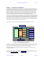
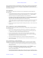
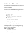
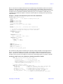
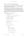
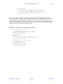
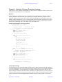
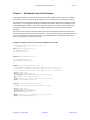
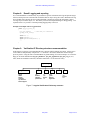
Verification Intellectual Property (IP)
Modeling Architecture
Guide to Structured Development
Using OpenVera
May 2002
Version 1.1
Verification IP Modeling Architecture
version 1.1
Authors:
Mehdi Mohtashemi
Azita Mofidian
Verification Technology Group,
Synopsys, Inc.
http://www.smartverification.com/
http://www.synopsys.com/products/hlv/hlv.html
http://www.open-vera.com/
Revision History
Version 1.1
Date
May 2002
Description
First release on open-vera.com page.
Copyright and Release information:
Vera, OpenVera, and OpenVera Assertion (OVA) are trademark of Synopsys, Inc. All usage is governed by legal
agreements. With proper credit, referencing and usage of the concept is permitted.
Send correspondence and clarifications to: [email protected]
© Synopsys, Inc. 2001-2002
May 2002
Page 2 of 32
Verification IP Modeling Architecture
version 1.1
Abstract
The ever increasing advances in the integrated circuit technology during the past decade has
made it possible for electronic system designers to assemble complete systems-on-chips (SoC).
As these System on chips have found their use in more and more computer, graphics, and
networking hardware systems the level and complexity of functionality within them have
dramatically increased. At the same time shrinking time to market leaves little room for errors
in the design. Hence functional verification has become one of the major tasks in committing
chips to fabrication. Just as designs are pushing more towards reusable and portable
environment so must the verification components and environment. Also, more technologically
advanced and high-pin packages allow each chip to have multiple bus interfaces, each of which
may share internal resources in parallel and increase the possible concurrent operations.
Therefore there has arisen a real and pressing need in the electronic design process for standalone, pre-verified and built-in verification infrastructure, which can be easily plugged in the
simulation-based validation tests. The Verification Intellectual Property (Verification IP) is an
integral and important component of such infrastructure and provides such mechanisms.
In this technical document we present a foundation of a modeling architecture for the structured
development of such verification components. The architecture is based on the concept of
layered methodology, which can be applied to general abstract and advanced testbench
development for ASICS and SoC and systems. In this paper the psuedo-code examples based
on OpenVera Hardware Verification Language are provided to show the fundamentals of the
modeling methodology. In addition, general usability guidelines related to development of
structured and re-usable code for verification IP, verification platform and infrastructure are
highlighted.
© Synopsys, Inc. 2001-2002
May 2002
Page 3 of 32
Verification IP Modeling Architecture
version 1.1
Table of Contents
Chapter 1:
Introduction to Verification IP ...............................................................................................5
Modeling Architecture Fundamentals ............................................................................................................6
Layering types................................................................................................................................................6
Layer 0: Signal Layer ................................................................................................................................7
Layer 1: Command Layer [protocol command and data packets] ...........................................................7
Layer 2: Transaction Layer [Traffic and checking].................................................................................7
Layer 3: Application Layer [Test scenario Generation and Checking Mechanisms] ...............................8
Bus Functional Model, Protocol Checking, Monitor and Functional Coverage ............................................9
Fully directed and pseudo-random tests.......................................................................................................10
Chapter 2:
Layer0, Signal Layer ............................................................................................................11
Chapter 3:
Layer1, Command [BFM, protocol, data] Layer..................................................................13
Chapter 4:
Layer2, Transaction and Traffic Generation and Checking .................................................16
Chapter 5:
Layer3, Test Scenario or Application Layer ........................................................................18
Chapter 6:
Monitors, Checkers, Functional Coverage ...........................................................................20
Monitors.......................................................................................................................................................20
Functional Coverage ....................................................................................................................................20
Protocol Checkers ........................................................................................................................................22
Chapter 7:
OVA based Protocol Rule Checkers ....................................................................................23
Chapter 8:
Result Logging and reporting...............................................................................................24
Chapter 9:
Verification IP Directory structure recommendation ...........................................................24
Chapter 10:
Usability guidelines..............................................................................................................25
Configuration management ..........................................................................................................................25
Naming convention ......................................................................................................................................25
Script and simulation control .......................................................................................................................25
Debug control level ......................................................................................................................................25
Array and list manipulation..........................................................................................................................25
Packet, Transaction Sequence and Device identification.............................................................................25
Error generation and handling......................................................................................................................25
Synchronization and concurrency ................................................................................................................25
Verification IP version and identification ....................................................................................................26
Verification IP modules and object model diagrams with UML..................................................................26
Documentation, data-sheet and application notes ........................................................................................26
Verification IP licensing and delivery mechanisms .....................................................................................26
Appendix A: A PCI arbiter psuedo-code example...........................................................................................27
Appendix B: Guideline and Methodology Checklist .......................................................................................31
© Synopsys, Inc. 2001-2002
May 2002
Page 4 of 32
Verification IP Modeling Architecture
Chapter 1:
version 1.1
Introduction to Verification IP
The Verification Intellectual Property (Verification IP) is the verification model and overall environment,
which aids designers and verification engineers in the task of validating the functionality of their design. The
Verification IP (VIP) is used in all levels of simulation-based verification. The Verification Intellectual
Properties are based on standard protocols used in Networking, computer and system designs, such as
PCI/PCIx, USB, Ethernet. These components are pre-verified to the standard protocols and contain the
necessary infrastructure for testbench generation and checking mechanisms as well as all the appropriate
routines to create individual protocols, commonly known as Bus Functional Models (BFM).
Verification IP components provide enhanced productivity to the system and ASIC designers by reducing the
time to create the verification infrastructure and testbench environment including the required models. The
verification IP based on OpenVera Hardware Verification Language (HVL) allows verification and design
teams to quickly and easily create random scenarios. They also allow users to easily create directed test
scenarios and test sequences for their designs. These test cases greatly aid users in finding functional bugs
early in design cycle, hence reducing the overall verification time.
A typical SoC and verification IP with representation of testbench environments is shown below:
External Memory
Design Under Test
CPU
Core IP
Memory
Controller
Serial
Ports
Serial I/O VIP
Control
Logic
Parallel
Ports
1284 VIP
Ethernet
Controller
Ethernet VIP
USB
controller
USB VIP
Prop. Bus
Controller
Proprietary bus
VIP
PCIx
Controller
PCI/PCIx VIP
VERA
Testbench
Infrastructure
Figure 1: A Typical SOC with Vera testbench
This technical document provides guidelines for structured development of such Verification IP. It discusses
requirements for modeling generators and checkers of standard protocols for a verification IP based on
1
OpenVera Hardware Verification Language using a layered testbench methodology.
The modeling guideline is based on the layered architecture, which defines four basic layers for each
Verification IP component.
1. The readers are referred to “OpenVera User Manual” for full syntax and feature explanation of the language which also contains
important information and guidelines on usage. Please refer to www.open-vera.com site. However for any questions and inquiries you
can send email to [email protected] for immediate response.
© Synopsys, Inc. 2001-2002
May 2002
Page 5 of 32
Verification IP Modeling Architecture
version 1.1
Modeling Architecture Fundamentals
A Verification IP defines the environment for simulating and testing the logical functionality of a given
protocol and connects at the physical (logic) levels to the design under test. These models may handle timing
checks for input/output signals.
The modeling architecture is based on the layered testbench methodology. Each Verification IP primarily
consists of four layers as follows.
Layer 0: Signal:
Layer 1: Command:
Pin Interface.
Protocol Command and Data Packets.
Layer 2: Transaction: High-level Transactions and Traffic Generation and Checking.
Layer 3: Application:
Test Scenario Generation mechanism
Figure 2 shows the overall picture of these four layers mentioned with a pseudo-code example.
Functional Coverage
Layer3: ApplicationFigure2: Representation of Layers in VIP
High-level test
Scenario
Generator
Layer2: Transaction
Domain Sepecific information
High-level
Transactions
Generators/checking
Data for test
scenarios
random-based and
directed infrastructure
Commands
Generation
[BFM]:
Sequence of
transactions [traffic]
Layer0:
Signal
Physical Signal
manipulation
[BFM]
Design
Under
Test
Local_read
Local_write
Random/directed
Directional
Communication
2Master/3Slaves
30%/50% Wr/Rd
distribution
Layer1:
Command
Monitors/
Checkers
Assertions
Functional
Coverage
Read/Write/Back-toBack/Write/Rd
MultiWr/RandomData/Address
Pci_read
Pci_write
inout bit [63:0] PA_Data
Figure 2: Representation of Layers in Verification IP with an example
Layering types
In general software development the there are two basic types of layering: Strict and Loose layering. The
concept of strict layering enforces the fact that the communications among elements within each layer be
moderated in such a way that there is a fixed and strict channel of access between each layer. This means that
there are only selected functions and tasks are allocated for passing information between layers. On the other
hand loose layering allows freer access within each layer.
© Synopsys, Inc. 2001-2002
May 2002
Page 6 of 32
Verification IP Modeling Architecture
version 1.1
In the Verification IP architecture a hybrid approach is modeled. Wherever possible strict layering should be
implemented, however, if there is a need to allow calls to be made amongst layers to make modeling more
user-friendly, it should be done with care. For example, accessing pin interfaces from the top layer, layer 3 or
the main program is allowed.
Layer 0: Signal Layer
Layer 0, signal layer or physical layer, allows direct access to Design-Under-Test (DUT) signals at the
physical boundary.
•
Provides signal and task level connectivity into the physical representation of the DUT. Each DUT
or modules of the system under test could be written in HDL, HVL, C/C++, or other languages.
•
Interfaces between the test environment (including other Layers) and the DUT.
For example, if the DUT is implemented in HDL and the rest of the testbench in OpenVera, then this
representation layer would simply consist of the interface file (.if file), the virtual port and bind
declarations, and the task declarations statements between DUT and Vera.
Another example would be if an emulation engine represents the DUT, then this layer would consist
of C-code that would connect OpenVera testbench to an emulation engine over the computing
network.
•
Monitors the design signals for physical interface checking and correctness. These can also be used
in upper layers.
Layer 1: Command Layer [protocol command and data packets]
The command layer implements the BFMs, protocol generation, checking routines, and monitor methods at
the most primitive levels.
•
It provides calls to BFM commands and contains the basic command for the standard protocol.
•
This layer can be controlled and configured per user application from layer1and the upper layers,
i.e., methods can be called in a directed environment if desired by users.
•
Provides for monitoring routines, checkers and self-checking components within the BFM.
•
Provides appropriate data-packet, data structure in the primitive classes with their corresponding
randomizeable parameters and built-in constraint mechanisms
•
Also provides initialization methods for the verification environment and design under test.
•
As an example, in the case of PCI Verification IP, this layer would consist of basic local pci_read
and pci_write commands.
Layer 2: Transaction Layer [Traffic and checking]
The transaction layer implements a high-level transaction generation. At this level, sequences of BFM
commands can be generated in a directed and automatic randomized fashion and checked for correctness.
•
Users can identify the order of the sequences and the distribution of sequence of transactions and
data packets at this layer.
•
For example in a PCI Verification IP, this can be a Read_back_to_back command or a
Read_write_seq command, where the command itself contains a sequence of lower level simple
pci_read or pci_write commands. Another example can be a burst read/write or
memory_write_multiple sequence.
•
The self-checking components provided in this level will use the lower layer commands, as well as
creating specialized formats for command generation, which gets mapped to routines and methods in
© Synopsys, Inc. 2001-2002
May 2002
Page 7 of 32
Verification IP Modeling Architecture
version 1.1
lower layers. For example, the data for pci_read and pci_write commands/transaction can be
compared with the expected data at layer 2.
•
The checking of results can also be done through a checker routine, i.e, a scoreboard or validation
mechanism that checks the actual output(s) against the expected value. This is usually accomplished
by feeding the generated data patterns to a checker engine, which then compares it with the value it
snoops from the output points.
•
This layer also handles proper logging of the results and statistics, usually to a file. Note that the
checking mechanisms, logging and statistics gathering can reside in this and the upper layer.
We also recommend the object-oriented paradigm for the structure of base classes and usage of extension to
the class and its methods. In this flow the main classes in the component are defined virtual requiring the
extension(s) to be defined and declared. This will maximize flexibility for re-use of verification IP.
Layer 3: Application Layer [Test scenario Generation and Checking Mechanisms]
The application layer is the highest-level abstraction in the Verification IP, where application specific test
scenarios can be generated in pseudo-random and full-directed environments.
•
The configuration of all the lower layers can be controlled from layer3.
•
Actual application services are reflected in this layer. In the PCI example, users should be able to
specify the number of Masters, Slaves and distribution of specific transactions per initiator or
Targets with test scenarios and sequences of transactions related to each Master and Slave.
•
This layer contains the intelligence to decode the scenarios to call appropriate lower level methods
and routines upon execution of transactions.
•
The checking mechanisms in this layer depend mainly on the routines/methods in lower layers.
These mechanisms can use scoreboard/checking engines in this layer in conjunction with the lower
layer routines and compare expected values with sampled values at appropriate outputs.
•
This layer provides proper logging and statistics gathering for the tests and scenarios.
Test suites
1-n
1
Random
& directed
Coverage objects
Configuration
Control
Traffic
Sequence
Generator
generation
Of adresses
and data
Extensions
Data/protocol checks
Monitor
Scoreboards
OVA Checker IP
BFMs, and Signal layer methods
Figure 3: A top-down view of Verification IP layered object formation
© Synopsys, Inc. 2001-2002
May 2002
Page 8 of 32
Verification IP Modeling Architecture
version 1.1
Bus Functional Model, Protocol Checking, Monitor and Functional Coverage
In conjunction with the layers described in the previous sections, let us note that the bulk of BFMs, the
protocol generators as well as protocol checking and monitoring scheme is intended to be embedded in the
signal and command layers. The functional coverage routines and methods will allow users to gather
information about tests, most importantly about standard protocols’ functionality coverage. As such, these
coverage methods should be accessible from higher layers and can act as templates for users to add their own
in the higher layers.
BFMs generate the input stimuli to the DUT. The methods described by BFM commands directly relate to the
functionality of protocol and would be configurable to users specific input.
Protocol checks and monitors are used to ensure the standard compliancy and monitor the correct bus
activities. Monitors are developed as integral part of verification IP and should be dynamic and include
specific and descriptive error messages that are user controllable. OpenVera technology allows protocol
checkers to be developed as an embedded part of the verification IP or as a standalone checker module.
The Verification IP embedded Checkers and Monitors are usually included in Layer1 and can be accessed by
all the layers. The OpenVera Assertions (OVA) as part of OpenVera HVL provide a clear, concise and
highly abstract mechanisms to describe sequences of events and to test for their occurrence. The OVA can
also be used to specify functionality to simulate and measure functional coverage. The template and macro
capability built in OVA allows creation of pre-verified stand-alone abstract checker modules and IP that will
be easily used and re-used in a simulation-based environment. Please refer to chapters 6 and 7 for more
explanation and example usage.
VERA Verification IP and verification environment
Test Scenario, Transaction
Sequence Generation
Constraints- randomization
Directed
Check Engine
Scoreboard
Generators
Generators
Monitors/ Checkers
Results Info and
Statistics, log
Design
Under Test
Monitors/
Checkers
Functional
Coverage
OVA based Protocol
Rule Checker IP
Figure 4: Representative verification environment with Verification IP
We also note that the testbench and Verification IP configuration is to be provided at higher layers, for
examples at layers 2 and 3. In this way a user can configure the Verification IP and allow the commands
and proper stimulus to be generated for exercising the DUT.
© Synopsys, Inc. 2001-2002
May 2002
Page 9 of 32
Verification IP Modeling Architecture
version 1.1
Fully directed and pseudo-random tests
The Verification IP environment uses the capabilities in OpenVera to allow creation of fully directed test
suites and random test cases from the same base with ease. The randomized test and sequence generation is
orchestrated through the constraint blocks. These blocks can be dynamically manipulated throughout the
simulation. The information about routines and parameters at each layer should be clearly documented to
allow users to create directed and focused test cases.
In the following chapters, we will first provide a brief description of the Verification IP layers followed by
a more detailed discussion of each layer. In this light, we provide pseudo-code as examples as well as
expected deliverables for such Verification IP.
© Synopsys, Inc. 2001-2002
May 2002
Page 10 of 32
Verification IP Modeling Architecture
Chapter 2:
version 1.1
Layer0, Signal Layer
Layer0 provides a signal level interface between the OpenVera Verification IP, its testbench infrastructure
and design under test (DUT), mainly assumed to be in a Verilog or VHDL representation. Note that in this
layer, template wrapper files are also provided between Vera environment and design under test. Interface
files (*.if.vrh) will provide a clean and manageable way to determine how OpenVera drives and samples
signals, defines the clock to which the signals are tied, and identifies a set of signals through which
OpenVera communicates with the HDL (DUT) environment. The recommended method for DUT signals
and internal nodes to be accessed is through virtual ports and its corresponding binding routines. Taking
PCI signal information as an example, we show the basic construct in the following paragraphs.
Virtual Ports and Bind constructs
It is most suitable to use the ports and bind features in OpenVera, where a virtual port contains a set of
signal members grouped together under a given name. Port signal members are arbitrary placeholders that
are then linked to the actual interface signals via binding. Example 1 shows an interface structure for PCI
protocol.
Example1: Interface file for a PCI BFM
interface PCI {
inout [63:0]
inout [7:0]
inout
inout
inout
inout
. . . }
AD
C_BE_
PAR
FRAME_
TRDY_
IRDY_
PSAMPLE
PSAMPLE
PSAMPLE
PSAMPLE
PSAMPLE
PSAMPLE
PCI_SAMPLE_SKEW
PCI_SAMPLE_SKEW
PCI_SAMPLE_SKEW
PCI_SAMPLE_SKEW
PCI_SAMPLE_SKEW
PCI_SAMPLE_SKEW
PHOLD
PHOLD
PHOLD
PHOLD
PHOLD
PHOLD
PCI_DRIVE_SKEW
PCI_DRIVE_SKEW
PCI_DRIVE_SKEW
PCI_DRIVE_SKEW
PCI_DRIVE_SKEW
PCI_DRIVE_SKEW
depth 1 ;
;
;
;
;
;
In example 2 a representative port and bind description are provided.
Example2: Ports and Binds to connect PCI signals to VERA interface signals:
port pci_port {
ad ;
c_be_ ;
par ;
frame_ ;
trdy_ ;
irdy_ ;
. . . }
bind pci_port
ad
c_be_
par
frame_
trdy_
irdy_
. . . }
PCI_BIND {
PCI.AD ;
PCI.C_BE_ ;
PCI.PAR ;
PCI.FRAME_ ;
PCI.TRDY_ ;
PCI.IRDY_ ;
Static and dynamic signal connections
Every Verification IP should contain static connection routines for use in the testbench, which can be
accomplished through directly incorporating hdl_nodes or through configuration (.vcon) file. In
conjunction with this ability to dynamically connect signals can be provided through signal_connect
methods. This method is a more reusable approach. The following example shows sample code for
signal_connect.
Example3: dynamic connection with signal_connect()
…..
signal_connect (pci_port.$ad, PCI.AD);
signal_connect (pci_port.$c_be_, PCI.C_BE_);
signal_connect (pci_port.$frame_, PCI.FRAME_);
……
© Synopsys, Inc. 2001-2002
May 2002
Page 11 of 32
Verification IP Modeling Architecture
version 1.1
Here we also show an example of direct connection using configuration “.vcon” file. For multiple
modules/mains, users can employ project-based configuration mechanism. VERA’s multiple module
support is based on its implementation of project-based methodology. There are three major components to
this approach:
A configuration (.vcon) file for each module
The VERA object (.vro) files for each module type
An overall project (.proj) file specifying VERA source code
The .vcon file’s “connect” statement can override an interface signal specification in the VERA program.
This includes changing port-connected interface signals to direct connect interface signals (and vice-versa),
and changing the HDL path to which signals are connected. Please refer to the OpenVera User Manual
for more details. The following sample code is an example of a .vcon file for PCI Verification IP.
Example 4: Sample OpenVera .vcon file for a PCI master
timescale 100ns/10ns
clock SystemClock period 100
connect
input
pcimaster.PCLK=testbench.u1.PCLK
connect
output
pcimaster.PIDSEL=testbench.u1.PIDSEL
connect
output
pcimaster.PGNTNN=testbench.u1.PGNTNN
connect
output
pcimaster.PRSTNN=testbench.u1.PRSTNN
connect
output
pcimaster.PSBONN=testbench.u1.PSBONN
connect
output
pcimaster.PSDONE=testbench.u1.PSDONE
. . .}
Verilog and VHDL top level test and Vera shell wrapper files
Since the Verification IP can be used in any mixed HDL environment, appropriate set of templates of top
test files and Vera shell wrapper files should be supplied with the model. The wrapper files and top-test
files will be modified by users in an SoC testbench environment since other models and interface
connections are needed and will be added as appropriate.
© Synopsys, Inc. 2001-2002
May 2002
Page 12 of 32
Verification IP Modeling Architecture
Chapter 3:
version 1.1
Layer1, Command [BFM, protocol, data] Layer
All primitive access methods for BFMs, monitors, checkers and packet data structures are implemented in
this layer. These BFM commands and activities at the input and output boundaries, as well as signal levels,
are also monitored at this level.
BFM and commands will be discussed in this chapter. There will be a more detailed review of functional
coverage, checking and monitors in chapter 6.
It is a requirement that the description of the BFM’s individual methods be encapsulated in OpenVera
Classes, following the object-oriented paradigm. Given that most standard protocols are sufficiently
complex, one can create low-level primitive methods (tasks and functions), which are used to create more
complex and complete full cycle transactions corresponding to specified protocols. Using a PCI standard
protocol, we will show sample pseudo code examples to highlight the modeling architecture.
Therefore in layer 0 and 1, we can define the lowest layers of the connection to device under test as well as
some combination of the functionality to create higher-level objects. For example in the PCI/PCIX case,
one may create the layers of object as follows: (Here the structure/header of arbiter class is shown. The
more detailed code is inserted in Appendix A)
Example 5: A psuedo-code for a pci_arbiter_model class
//include appropriate header files
// for example extern for SynPCIprnt object
class Syn_Pci_arbiter_model {
pci_port devPrt, // binds to the PCI bus
integer type,
// priority rule (Round_Robin or Two_Level_Round_Robin)
integer parking
// 0: do not park, 1:park to the last winner
task new (pci_port inPrt, integer type, integer parking, … );
task pci_arbiter_start(..);
…
} //end of class Syn_Pci_arbiter_model
task Syn_Pci_arbiter_model::new (pci_port inPrt,..)
{
devPrt = inPrt; // make the object binding singals
…..
} // end of new task
task Syn_Pci_arbiter_model::pci_arbiter_start(..)
{
integer rstlast, lastwinner, lastwinner2, winner, curwinner, granted;
bit [7:0] req_, gnt_, gnt_l;
bit frame_, irdy_, rst_;
if( (type != Two_Level_Round_Robin && type != Round_Robin) || (parking > 1) )
SynPCIprnt.SynPrint("Illegal argument for pci_arbiter_model()\n");
…..
} // end of task pci_arbiter_start
In this layer, appropriate classes must be developed to allow creation of devices specific to the standard
protocol. For example, for an Ethernet design, a receiver class and a transmitter class should be defined.
For the above example of PCI, one defines a master_device class as well as target, etc. The following
header code shows the class for a PCI master device. This class will have methods, which use primitive
bus functional methods to interact with the design under test. Note that these primitive sets can be hidden
from the users and only be used to define a PCI master device.
Example 6: a class describing PCI Master device
class Syn_pci_master_device {
pci_port devPrt, // binds to the PCI bus
integer mid
// Master id, which REQ to be used (0-7)
...
task new (pci_port inPrt, integer inMid); // binds to the PCI port
task pci_master_burst(..);
task pci_master_arb (..);
…
} // end of the class Syn_pci_master_device
© Synopsys, Inc. 2001-2002
May 2002
Page 13 of 32
Verification IP Modeling Architecture
version 1.1
Here we also show an example of data structure for an Ethernet packet definition, which can be used as a
template for similar packet data description. The following shows a partial Ethernet Mac packet frame
description. Note that the randomization and serialization attributes have been inserted here for use in this
and upper layers to automatically randomize fields with a given set of constraints. Usually this set of
constraints can be defined as template so that users can then add more according to their specific design
implementation.
Example 7: Example of an Ethernet data packet class with randomization
virtual class Syn_Ether_packet {
integer Pkt_Id;
// for purpose of keeping track of pkt
rand {
packed bit [47:0] dest;
packed bit [47:0] srce;
packed bit [15:0] type;
bit [15:0] length;
packed bit [7:0] data [] assoc_size lenght;
…..
}
packed bit [31:0] crc; // calculated after randomization
// can describe constraints which are controlled from higher
// layers by accessing the string name of each constraint
constraint srce_range {
srce < MAX_SRC;
srce > MIN_SRC;
}
constraint dest_range {
dest == (type_set) ? void : srce);
}
constraint Pkt_lengths {
length dist {
RANGE_1 :/ dist_1,
RANGE_2 :/ dist_2,
..}
task new(..);
task pre_randomize(..);
task calculate_crc(..);
task post_randomize(..);
...
} //end of class Syn_Ether_packet
We noted the fact that primitive methods maybe required in complex standards to form higher abstract
objects. For our PCI example, one can create a set of primitive routines that access the PCI bus as a
master. Therefore the combination of primitive tasks completes a full bus command for PCI protocol.
Example 8 shows a pseudo-code sample for a master burst read through sequences of primitive methods.
Example 8: sample code for bus command by combining the primitive methods
task Syn_pci_master_device::pci_master_burst (
....
pci_master_arb( .. ) ; // get bus arbitration
pci_master_rd_init( .. ) ; // initiate master read
repeat ( number_of_burst_cycles - 1 )
pci_master_rd_sub( .. ) ; // subsequent master read
//end of pci_master_burts method
)
// Another example of method
task Syn_pci_master_device::pci_master_arb(
integer dly,
// Number of cycles to delay before asserting REQ.
integer mid,
// Master id, which REQ to be used (0 - 7).
integer max_latency,
// Maximum latency to wait for grant.
bit lock,
// = 1 means the master wants lock ownership.
var integer ret_status,
// Return status, 0:success, -1:failed
(bit keep_request = 1'b0) // = 0 request is released with grant
// = 1 request is held asserted even after grant
.......
)
© Synopsys, Inc. 2001-2002
May 2002
Page 14 of 32
Verification IP Modeling Architecture
version 1.1
A similar class can be created for pci_target_core_device with appropriate methods to properly respond to
activities on the bus according to the protocol.
Example 9: An example of pci_target_core_device
class Syn_pci_target_device {
pci_port devPrt
// binding the signals
.....
// local paramters for device manipulation
bit [15:0]
device_id;
local bit [15:0] vendor_id;
local bit [7:0] revision_id;
local bit [7:0] mem_space[];
local bit [7:0] iom_space[];
local bit [7:0] cfg_space[];
task
task
task
task
task
task
task
task
new ( pci_port inPrt, ...);
terminate_target(..);
device_config(..);
pci_target_rd_init(..);
pci_target_rd_sub(..);
target_rd(..);
target_burst_rd(..);
start_target_model(..);
...
} // end of class
task Syn_pci_target_device::new(pci_port inPrt,..){
..
devPrt = inPrt;
//binds to the PCI signals.
// device is instantiated
...
}
Note that because of the complexity of the protocol set of primitive routines (atomic activities which allow
full bus commands) a class is formed by combining the target driver primitives. Example 10 below shows a
sample code for PCI target burst read method.
Example 10: Sample code combination for Target Burst Read method
task Syn_pci_target_device::trgt_burst_rd (
....
pci_target_rd_init (..);
// initiate target read wait
repeat (number_of_burst_cycles -1)
pci_target_rd_sub(...);
// subsequent target read
)
task Syn_pci_target_device::trget_rd (
...
pci_target_rd_init(..);
pci_target_rd_sub(..);
... )
}
The following shows a typical sequence of primitives for running a target model, which comes alive and
responds correctly to actions.
Example 11: Sample code for a PCI Target using primitives
task Syn_pci_target_device::start_target_model(
....
pci_target_rd_addr(...);
// With TCTL_MONITOR on
// Check the returned address and command to see if we should repond
if (respond)
{
if (read_response)
{ pci_target_rd_devsel(...); // Respond with a device select
pci_target_rd_sub(...);
// Do a read data transfer.
...}
else
{ pci_target_wr_devsel(...); // Respond with a device select
pci_target_wr_sub(...);
// Do a write data transfer.
...}
Initialization routines
Proper device initialization routines and register and pin setups must be carefully crafted, so that upon start
of test, no unknown behavior is seen and the test suite and design are in a known and correct state.
© Synopsys, Inc. 2001-2002
May 2002
Page 15 of 32
Verification IP Modeling Architecture
Chapter 4:
version 1.1
Layer2, Transaction and Traffic Generation and Checking
At this level, the Verification IP must provide an abstraction layer through objects and classes with its own
specific and appropriate randomization/constraint methods that allow creation of fully directed and pseudorandom sequences of higher-level transactions to stimulate the DUT. Implementation of result checking
through self-checking mechanisms are embedded and used here. The checks can be accomplished using an
engine or scoreboard methods that compare sampled outputs with expected values, which are provided by
the traffic/data/transaction generation routine.
For generation methods, the guideline is to place the overall structure in classes, which use automatic
randomization routines to assemble a legal sequence of transaction and data packets. Each sequence must
then be decoded and dispatch appropriate routines in lower layers to drive and sample data to the DUT.
In a sample example using the PCI environment, we show a simple structure, which can be used as a base
to create sequences of activities on the bus.
Note that the functional coverage routines for BFM command activities should be connected in this layer to
provide for reporting and statistics gathering. We also note that each transaction can be defined in a task
or class method. Constraint setting and automatic randomization of fields within each transaction must be
appropriately defined and declared according to each specific standard protocol requirements.
Below is an example of setting constraints to some of the fields of PCI I/O read and I/O write commands,
which are all defined in a Class called “Syn_Pci_cmd_operation”.
Example 12: Sample code for a PCI command Operation Class
class Syn_Pci_cmd_operation {
rand bit [31:0] addr;
// Address for 32 bit PCI accesses
rand bit [63:0] data[20];
// PCI data
rand integer
byte_cnt;
// Number of bytes to transfer
….
constraint c_io_wr {
// Constraint for I/O Writes
byte_cnt dist {1 :/ 30, 2:16 :/ 70};
addr > IO_L_0;
addr < IO_U_0 - (byte_cnt * 4);
}
constraint c_io_rd {
// Constraint for I/O Reads
byte_cnt dist {1 :/ 100, 2:16 :/ 100};
addr > IO_L_0;
addr < IO_U_0 - (byte_cnt * 4);
}
task new(..);
task get_opr(integer icommand);
task do_cmd (..);
..
} //end of class definition
task Syn_Pci_cmd_operation::new(..) {
void=constraint_mode(OFF,”c_io_rd”);
void=constraint_mode(OFF,”c_io_wr”);
} //end of task new!
task Syn_Pci_cmd_operation::get_opr(integer icommand)
string constr;
bit [32:0] max_addr;
bit [36:0] addr_index;
{
case(icommand) {
IO_RD
: constr = “c_io_rd”;
IO_WR
: constr = “c_io_wr”;
}
void=constraint_mode(ON,constr);
void=randomize();
void=constraint_mode(OFF,constr);
}
//end of get_opr task
task Syn_Pci_cmd_operation::do_cmd (..// decode the above and call appropriate
//bfm routines from master/target device
}
// end of Pci_cmd_operation
© Synopsys, Inc. 2001-2002
May 2002
Page 16 of 32
Verification IP Modeling Architecture
version 1.1
Note that in the example above, the c_io_rd and c_io_wr methods could be defined in a separate class or in
the same class, or be part of the BFM class itself.
One other advanced method to introduce a higher level of randomization is to use Vera sequence
generation feature in conjunction with the above mentioned class structure, in this case the cmd_operation
class. A sample code follows:
Example 13: Example of Vera Sequence Generator (VSG), randomizing PCI commands
….
class Syn_Pci_cmd_generator
{
….
Syn_Pci_cmd_operation opr;
….//other variables
task new(…);
task set_dist_param(..);
task set_cmd_seq(..);
..
}
..
..
task Syn_Pci_cmd_generator::set_cmd_seq (..)
// other parameter settings
..
// here use the appropriate vsg style
randseq()
{
commands:
io_rd_prod | io_wr_prod |
mem_rd_multi_prod;
io_rd_prod: &(io_rd_cmd_w) io_rd_cmd;
io_rd_cmd:
{
opr.get_opr(IO_RD);
do_cmd(2, mstr);
};
io_wr_prod: &(io_wr_cmd_w) io_wr_cmd;
io_wr_cmd:
{
opr.get_opr(IO_WR);
do_cmd(3, mstr);
};
mem_rd_multi_prod: &(mem_rd_multi_cmd_w) mem_rd_multi_cmd;
mem_rd_multi_cmd: {
opr.get_opr(MEM_RD_MULTI);
do_cmd(12, mstr);
};
} // end of randseq
)
…..//other routines.
Resultant data and response from the design should be checked through check engine and appropriate selfchecking routines in this layer.
© Synopsys, Inc. 2001-2002
May 2002
Page 17 of 32
Verification IP Modeling Architecture
Chapter 5:
version 1.1
Layer3, Test Scenario or Application Layer
This layer is the highest level of interaction with the DUT for test suite creation. At this level, users will
have control over creating a combination of different test scenarios based on the specific application.
Through setting parameters either in the constraint segments of the class or parameters for the sequence
generation, psuedo-random test suites can be generated.
Checking the results is of course more domain specific. For example for a PCI test, one may want to
follow memory access of a master device with a follow-on transaction that checks the validity of the data.
For a networking design, a packet or frame received at the receiver side can be checked via a minireference mechanism at the transmit side. In this layer, a Verification IP must also provide facilities to
allow checking of all transactions at the end of the simulation. In a networking testbench environment, one
can use this to check that all packets and frames have arrived at their destination sides. The following is an
example of a class for test scenario, using the psuedo-code for PCI. This class is responsible for holding a
user-defined scenario, and executing the test, stimulating the design and checking the response as specified
in the scenario.
Example 14: A sample code for test environment class
class Syn_Pci_test_gen {
// local variables for control of test -- distribution
// and random sequences
integer test_seq;
bit
directed;
// can be used to bypass all randomization
string test_flow_name; // for identification purposes
// instantiate targets/masters/monitors/checkers/
// and coverage elements object holders
Syn_Pci_master_device sPciM[];
Syn_Pci_targer_device sPciT[];
Syn_Pci_monitor
sPciMntr[];
Syn_Pci_arbiter_model sPciArb;
Syn_Pci_coverage_core sPciCvrg;
Syn_Pci_Prtcl_Check
sPciChk;
Syn_Pci_cmd_generator sPciCmd;
task new(string test_flow_name);
// initialize all objects with appropriate parameters
task setup_config(..);
task setup_test_seq(..);
task start_test_seq(..);
..
} //end of class definition
task Syn_Pci_test_gen::setup_test_seq (..)
{
while (Syn_Pci_not_end_of_test) {
// setup parameters here
randseq () {
// ..
PCI_TESTS:
&(memory_dist) MEMORY_SEQ |
&(io_dist)
IO_SEQ |
&(complx_dist) INTERLEAVED_SEQ |
&(directed) TEST_SUITE_DIRECT;
MEMORY_SEQ:
&(parma1)
{sPciCmd.set_dist_param(..);
sPciCmd.set_cmd_seq(..);} |
&(rpt_factor) MEMORY_SEQ;
IO_SEQ:
&(parma3)
{sPciCmd.set_dist_param(..);
sPciCmd.set_cmd_seq(..);} |
&(rpt_factor) IO_SEQ;
© Synopsys, Inc. 2001-2002
May 2002
Page 18 of 32
Verification IP Modeling Architecture
version 1.1
//..
TEST_SUITE_DIRECT:
//.. Directly and easily setting parameters and calling
//
routines to generate desired and controlled sequences
//
without constraint manipulation and with ease.
//
Or calling a sequence generated or test-vectors created in
//
advance for specific compliancy test.
}
We can now see what a sample test would consist of. The following code segment shows the basic
structure of the main test program. Note that parameters for the lower modules and layers can be set from
this main highest level. In a typical SoC environment, instances of other verification IP such as USB,
Ethernet, will be instantiated in this main test program level. The interaction between the device under test
and verification IP through user-defined scenarios, which are executed, by the verification IP should be
carefully monitored and recorded to validate the design.
Example 15: A sample code for main program test routine
….
#include <vera_defines.vrh>
// include appropriate header files as well as
// external custom HDL and/or c/c++ routines.
#include “pci_master.vrh”
#include “pci_slave.vrh”
program main_test {
// instantiate individual masters/targets
// or call the test scenario generator for example.
Syn_Pci_test_gen test1Seq;
// ..
test1Seq = new(..); //proper objects
test1Seq.setup_config();
test1Seq.setup_test_seq();
test1Seq.start_test_seq();
test1Seq.start_check_engine();
test1Seq.generate_report();
..
..
}
© Synopsys, Inc. 2001-2002
May 2002
Page 19 of 32
Verification IP Modeling Architecture
Chapter 6:
version 1.1
Monitors, Checkers, Functional Coverage
In this chapter, a basic guideline and methodology is discussed for developing the monitors, checkers, and
functional coverage modules for the verification IP.
Monitors
As described in previous chapters, monitor routines should be embedded in class structures. Users can
define a virtual base class for monitor objects, which act as a template and will be extended to define
additional methods. These monitor objects can be called from different layers independent of how many
BFM are actually instantiated by users. In our PCI example, where many master and target devices can be
instantiated in the testbench environment, users should be able to use one set of monitor object to handle
the bus activity monitoring. Here is an example of two PCI monitor class.
Example 16: PCI Initiator and Target Monitors
virtual class Syn_Pci_monitor
{
pci_port devPrt;
// binding the signals
.....
// local paramters for device manipulation
bit [15:0]
device;
task new ( pci_port inPrt, ...);
task pci_monitor(..);
task print_status(..);
….
} //end class Syn_Pci_monitor
task Syn_Pci_monitor::pci_monitor()
{
fork
while(Syn_Pci_not_end_of_test)
{
bit [3:0] ret_cmd;
bit [63:0] ret_addr;
integer ret_status;
pci_rd_addr (..);
// ..
print_status(ret_status);
}
join none
}
class Syn_PCI_Mon extends Syn_Pci_monitor()
{
// specific information required per monitor
// paramters for device manipulation
bit [15:0]
Mon_device;
task new ( pci_port inPrt, ...);
task Special_pci_monitor(..);
task Special_print_status(..);
} //end class Syn_PCI_Mon
task Syn_PCI_Mon::Special_pci_monitor()
{
//set appropriate parameters
pci_monitor(..); // call routine
}
Functional Coverage
The functional coverage routines and methods will allow users to gather information about the stimulus as
well as the standard protocols. Users of VIP will use the provided coverage object as template and add their
own coverage definitions. The same approach as described for monitors can be used in this case. That
means creating a virtual based class that could be extended by users’ defined-classes. Coverage objects can
be defined in this virtual based class and can be turned “OFF” by default. All Verification IP layers should
be able to access these objects through appropriate methods. Sample coverage module is shown below.
© Synopsys, Inc. 2001-2002
May 2002
Page 20 of 32
Verification IP Modeling Architecture
version 1.1
Example 17: Sample coverage definitions for PCI Commands, address modes, Transaction
coverage_def Syn_pci_cmd_cov (bit[4:0] addr_cmd)
{
coverage_option = LO;
state Int_Ack_32
(5'b1_0000);
state Spec_Cyc_32
(5'b1_0001);
state IO_Rd_32
(5'b1_0010);
state IO_Wr_32
(5'b1_0011);
…..}
coverage_def Syn_pci_term_cov (bit[4:0] ctrl_sig)
{
/*** check for PCI control signals and define valid transactions ***/
state cycle_start
(5'b01111),
mstr_rdy_b
(5'b00111),
mstr_rdy_s
(5'b10111),
data_xfer
(5'b00001)….;
/*** Define all valid states of control signals
trans vld_cyc_start (
"mstr_rdy_b" -> "cycle_start",
"mstr_rdy_s" -> "cycle_start",
"data_xfer" -> "cycle_start",
"trgt_abort" -> "cycle_start",…..;
***/
…..}
coverage_def Syn_pci_tx_cov (bit[8:0] pci_tx_type)
{
coverage_option = LO;
/*** I/O Read and Writes***/
state IO_Rd_32_S_Norm
(9'h041),
IO_Rd_32_B_Norm
(9'h042),
IO_Rd_32_MAbt
(9'h043),…..;
state
IO_Wr_32_S_Norm
(9'h061),
IO_Wr_32_B_Norm
(9'h062),
IO_Wr_32_MAbt
(9'h063),….;
coverage_goal = 100;
} // end of pci_tx_cov coverage definition
These coverage definitions can be encapsulated in a coverage class as shown below.
Example 18: Sample code for PCI Coverage Class
class Syn_Pci_coverage_core
{
pci_port devPrt;
// bind the pci connection
bit [15:0] supported_cmd;
bit global_coverage;
bit accumulate_cov;
Syn_pci_cmd_cov
cmd_cov;
Syn_pci_term_cov term_cov;
Syn_pci_tx_cov
tx_cov;
event
start_cmd_cov;
event
start_term_cov;
event
start_tx_cov;
task new(..);
task coverage_monitor(..);
task coverage_report(..);
…….
}// end of class definition
task Syn_Pci_coverage_core::coverage_monitor(..)
{ …….
cmd_cov = newcov(addr_cmd, sync(ALL,start_cmd_cov));
term_cov = newcov(ctrl_sig, sync(ALL,start_term_cov));
tx_cov = newcov(pci_tx_type, sync(ALL,start_tx_cov));
……} //end of task Syn_Pci_coverage_core::coverage_monitor
task Syn_Pci_coverage_core::coverage_report(..)
{..
//control reporting mechanism for coverage commands
}
© Synopsys, Inc. 2001-2002
May 2002
Page 21 of 32
Verification IP Modeling Architecture
version 1.1
Protocol Checkers
The function of protocol checkers is to insure that the logical activities on the I/O bus comply with the
standard protocol definition for the bus architecture. The checkers would be able to flag any violation from
the protocol standards. The functionality of checker should be organized in a base class which can be
extended on a need basis.
Example 19: Sample code for PCI protocol check class
class Syn_Pci_Prtcl_Check
{
pci_port devPrt;
// bind the pci connection
..
task new(..);
task pci_mstr_ret_status(..);
task pci_check_reset(..);
task pci_check_interrupt(..);
task pci_check_perr(..);
task pci_check_dpar(..);
task pci_cache_snoop(..);
…….
}// end of class definition
task Syn_Pci_Prtcl_Check::pci_mstr_ret_status( bit [31:0]
errormask,
var integer
Syn_Pci_ret_status
)
{
bit [31:0]
status;
status = Syn_Pci_ret_status;
status = status & ~(errormask|MSTR_FATAL);
if (status)
{
if (status & MSTR_NORMAL)
SynPCIprnt.SynPrint ("MSTR: Unexpected NORMAL termination from target occurred\n");
if (status & MSTR_RETRY)
SynPCIprnt.SynPrint ("MSTR: Unexpected RETRY from target occurred\n");
if (status & MSTR_DISCON)
SynPCIprnt.SynPrint ("MSTR: Unexpected DISCONNECT from target occurred\n");
..
..);
if (!flag(OFF))
{
SynPCIprnt.SynPrint ("MSTR: Internal error, unknown error status found\n");
flag(OFF);}
Syn_Pci_ret_status |= MSTR_FATAL; // Mark that a fatal error has occurred.
}
task Syn_Pci_Prtcl_Check::check_dpar(
bit [7:0] ben,
bit [63:0] data,
bit dt_par_err,
// pretend data parity error
bit err_dperr,
bit err_dperr64,
bit [63:0] ad,
bit [7:0] c_be_,
bit mode64
)
{
bit par, par64, epar, epar64;
epar = ^ { ad[31:0], c_be_[3:0] };
epar64 = ^ { ad[63:32], c_be_[7:4] };
@(posedge devPrt.$clk);
par = devPrt$par; par64 = devPrt.$par64;
// Print out error messages if enabled
if (err_dperr && par !== epar)
SynPCIprnt.SynPrint("TARG-WR: Data parity error got PAR = %0b expected = %0b
(data=%0h,ben=%0h)\n", par, epar, data, ben);
if (mode64 && err_dperr64 && par64 !== epar64)
SynPCIprnt.SynPrint ("TARG-WR: Data parity error got PAR64 = %0b expected = %0b
(data=%0h,ben=%0h)\n", par64, epar64, data, ben);
}
© Synopsys, Inc. 2001-2002
May 2002
Page 22 of 32
Verification IP Modeling Architecture
Chapter 7:
version 1.1
OVA based Protocol Rule Checkers
As discussed in chapter 1, OpenVera Assertion (OVA) provides a highly abstract and concise declarative
mechanism to code the specification of the sequences of events and activities of a standard bus protocol.
The Assertion based verification component embodied in OVA protocol rule checker can work in a standalone mode, i.e, can be plugged in any design verification environment, which uses the standard protocol
without disturbing the structure. The function of protocol rule checkers is to insure that activities on the
I/O bus do not deviate from standard protocol definition and report any violation from the standard
operation.
For example, a PCI compliance protocol checker can be developed using the abstraction in OVA syntax
that is used in dynamic simulation of a PCI based SoC. Note that the same OVA checks and assertions can
also be used in formal verification environment for the standard protocol. The following example shows
psuedo-code segments of a protocol rules check.
Example 19: Sample code for OVA based PCI compliance rule checker
// include appropriate header files for macros
// and template use
module Syn_Pci_MstrSlv_check (…) {
…
Syn_PciMaster_check(…);
Syn_PciSlave_check(…);
}
template Syn_PciMaster_check(…):{
…
Syn_Pci_BusOptn_Rule_8_b(…);
Syn_Pci_BusOptn_Rule_8_c(…);
…
}
template Syn_Pci_BusOptn_Rule_8_b (clk): {
// Once FRAME has been de-asserted, it cannot reassert in the same
// transaction. If FRAME is de-asserted and the cycle is not yet over
// (i.e. IRDY is still asserted), then FRAME must not be re-asserted.
clock posedge clk {
event Syn_Pci_BusOptn_rule_8_b :
if( matched SynPciFrame_deassert_and_transact_not_over)
then #1 inv( SynPci_frame_asserted);
}
assert SynPciOp_8_b_frame_not_reassert_in_same_transact :
check( Syn_Pci_BusOptn_rule_8_b);
}
template Syn_Pci_BusOptn_Rule_8_c (clk): {
// FRAME cannot be deasserted unless IRDY is asserted
clock posedge clk {
event Syn_Pci_BusOptn_rule_8_c :
if( matched SynPciFrame_deassert)
then SynPci_irdy_asserted;
}
assert SynPciOp_8_c_frame_deassert_only_if_irdy_assert :
check( Syn_Pci_BusOptn_rule_8_c);
}
© Synopsys, Inc. 2001-2002
May 2002
Page 23 of 32
Verification IP Modeling Architecture
Chapter 8:
version 1.1
Result Logging and reporting
It is recommended that a central facility be provided for specific verification IP for log and print messages.
All files and objects in the verification IP would then share an object to log the results. Methods in the log
object should clearly identify the object and method that is printing or logging the information, such as
coverage object or arbiter object, etc. This facility can also control option setting for debug printing. The
required feature is to provide a consistent printing/logging utility to the user.
Example 21: Sample code for log-print Class
class Syn_Pci_print_obj
{
pci_port devPrt;
// bind the pci connection
string print_string;
..
task new(..);
task SynPrint(..);
task SynPCIsetDebugLevel(..);
...
…….
}
Chapter 9:
Verification IP Directory structure recommendation
In this chapter, we discuss a recommended directory structure and file naming convention. All the source
codes which are independently compiled use *.vr extension. File names should also contain a unique
prefix or postfix. Using the same recommendation for global naming, for our PCI example, we can use the
Syn_ for file name identification (Syn_Pci_models.vr, Syn_Pci_signal.if.vrh, Syn_Pci_cvrg.vr, etc.).
Files, which are included in other files, should be named with .vri extension for clarity.
VIP_Directory
design under test
Verilig
VHDL
Design
examples
Top-test files
Shell wrappers
include
lib
.vrh
Headers
interface
ports/binds
.vr
.vro
Source
.vri
doc
User
guide
Manual
AppNotes
test
sim
.vrl
Scripts
.ini
Figure 5: A typical Verification IP directory structure
© Synopsys, Inc. 2001-2002
May 2002
Page 24 of 32
Verification IP Modeling Architecture
version 1.1
Chapter 10: Usability guidelines
In this chapter we will highlight guidelines to ensure robust usability of the verification IP and models. The
following items will enhance re-use methodology and allow verification teams to incorporate the layered
verification IP in the testbench infrastructure.
Configuration management
The Verification IP code must take care of all default setting. For example, log files and coverage report
files must have default strings. Through appropriate mechanism such as plus argument, passing the
defaults can be overruled. This will allow users to customize the VIP environment.
Naming convention
In general the verification IP files and codes will be used in conjunction with other Vera testbenches. This
can potentially cause collision on names of data structures and methods. It is required that global variables
and data_types and structures such as classes use appropriate prefix or post-fixes. This also allows easy
identification of modules for debugging purposes. In this document all classes and global variables have
used a Syn_ prefix as an indication that they belong to Synopsys, Inc. library. For example, look at class
Syn_Pci_arbiter_model.
Script and simulation control
The verification IP contains appropriate make files, run-command files and scripts. These scripts must be
tested for the environment settings as well compilation and running a simulation with standard Verilog and
VHDL simulator such as VCS and Scirocco. The Verification IP users may choose to use the provided
scripts or modify them to incorporate in their system simulation scripts.
Debug control level
It is customary to use print statements to aid in debugging both the verification IP and testbench code. The
requirement is to use debugging level identifiers that can be controlled, say from a plus argument or set of
variables, by users. Refer to logging and reporting section for more information.
Array and list manipulation
List structures within Vera and dynamic associative arrays are used for storage purposes. The associative
arrays should be handled properly. For example, the structures which are not needed should be deleted
using appropriate assoc_array(DELETE) routines, etc. Another method to reduce the chance of allocating
more storage/memory when packets/frames/data structures are created is to use appropriate default
allocation limits for input queues of data packets.
Packet, Transaction Sequence and Device identification
For statistic gathering as well as finer control of the test suites, data generation and checking, sequence
identification and packet identification such as packet_id, sequence_id, device_id, etc should be part of
each object and properly manipulated (incremented and registered in the logs and checks).
Error generation and handling
The verification IP model contains capability to easily create and generate error conditions and injection to
the DUT. It also should allow for checking the correct design response to the errors generated.
Synchronization and concurrency
The synchronization construct and features of Vera such as semaphores, mailboxes, regions and events
must be used for accurate handling of any thread manipulation. Please note the naming convention
discussed above for the identification of these constructs. For example arbitration mechanism most likely
would use a set of semaphore keys for control purposes.
© Synopsys, Inc. 2001-2002
May 2002
Page 25 of 32
Verification IP Modeling Architecture
version 1.1
Verification IP version and identification
Each verification IP shall be registering its appropriate name and identify in a print statement the developer
information for identification purposes. Information regarding code version and standard compliancy
levels must also be available in the verification IP code.
Verification IP modules and object model diagrams with UML
Unified Modeling Language (UML) is a language used mainly in software design for creating models of
object-oriented systems. Since UML is a graphical entry language and environment it can assist developers
of verification IP with specification, documentation and visualization of the objects and their interactions.
Most UML diagrams and some complex symbols are graphs containing nodes connected by paths. The
information is mostly in the topology. Data object and class diagram, along with activity diagram would be
helpful to the users of the verification IP, as it can provide a visual description and overview of the system
2
and class methods and data . The associations and aggregation, interaction between classes can also be
represented in the UML diagrams. The following figure is a sample representation of data object model,
using Vera extension to Rational Rose package.
UML data objects diagram model
Figure 6: A sample data object model in UML
Documentation, data-sheet and application notes
A concrete and all-encompassing data-sheet and a manual, a user guide should accompany verification IP
package. The user guide must detail how one would deploy the model in verification environment.
Application note(s) are customary for more clarification and expanded explanation. There should be a
quick-start section with a typical small test case at the minimum for a Verilog and VHDL environments
that shows the verification IP usage in each case.
Verification IP licensing and delivery mechanisms
The Verification IP code can be provided as object and protected format or complete source code. If the
objects are provided for use, then proper licensing and delivery mechanisms should be part of the
verification IP and its usage clearly documented. The simplest method is to use user-defined-function
mechanism to embed license checking and manipulation.
2. For more discussion on UML and object modeling readers can refer to following book and technical papers among many:
James Martin, James J. Odell, ‘Object-Oriented Methods, A foundation’.
“Mapping Objects to Data Models with UML” http://www.rational.com/media/whitepapers/tp185.pdf
“UML and Data Modeling” http://www.rational.com/media/whitepapers/Tp180.PDF
© Synopsys, Inc. 2001-2002
May 2002
Page 26 of 32
Verification IP Modeling Architecture
version 1.1
Appendix A: A PCI arbiter psuedo-code example
An expanded psuedo-code segments for a PCI arbiter and coverage class is shown in this appendix. These
are fragments of code to show the flow; this code is not a complete implementation.
//
// assumption that all required header files have been included properly
// and external objects/parameters have declare.
// example: extern Syn_pci_print_obj SynPCIprnt
class Syn_Pci_arbiter_model {
pci_port devPrt, // binds to the PCI bus
integer type,
// priority rule (Round_Robin or Two_Level_Round_Robin)
integer parking
// 0: do not park, 1:park to the last winner
task
new ( pci_port inPrt, integer type, integer parking);
local function integer RR_winner( integer last, bit[7:0] req_ );
local function integer Two_Level_RR_winner( integer last, integer last2, bit[7:0] req_ );
task pci_arbiter_start();
..
} // end of class Syn_Pci_arbiter_model definition
task Syn_Pci_arbiter_model::new( pci_port inPrt, integer inType, integer inParking)
{
devPrt = inPrt;
type =inType;
parking = inParking;
SynPCIprnt.SynPrint(" PCI arbiter model is instantiated \n");
pci_arbiter_start();
} // end of new task
// define what the RoundRobin winner method function
local function integer Syn_Pci_arbiter_model::RR_winner(integer last, bit[7:0] req_ )
{
integer i;
for( i = 0; i < 8; i++ )
{
if( req_[(last+i+1)%8]==1'b0 )
{
RR_winner = (last+i+1)%8; // set return value
return;
}
}
} // end of RR_winner function
// Some comments on the code for function described below.
// This is an example of 2Level Round Robin arbitration. Even number requests
// are higher in priority with the last winner having lower priority among the same
// priority level. If there is no request, it returns X.
local function integer Syn_Pci_arbiter_model::Two_Level_RR_winner(
integer last, integer last2, bit[7:0] req_ )
{
integer i, j;
integer current1, current2;
// if last was 2nd (odd) level, then scan 1st (even) level requests first.
//
current1 = (last & 1) ? 0 : (last + 2) % 10;
for( i = 0; i < 5; i++, current1 = (current1+2)%10 ) // scan 1st level
{
if( current1 == 8 ) // 2nd level's turn
{
current2 = (last2 + 2) % 8;
for( j = 0; j < 4; j++, current2 = (current2+2)%8 ) // scan 2nd level
{
if( req_[current2]==1'b0 )
{
Two_Level_RR_winner = current2; // set return value
return;
}
}
}
else if( req_[current1]==1'b0 ) // test for 1st level request
© Synopsys, Inc. 2001-2002
May 2002
Page 27 of 32
Verification IP Modeling Architecture
version 1.1
{
Two_Level_RR_winner = current1;
return;
// set return value
}
}
} // end of function Two_Level_RR_winner
task Syn_Pci_arbiter_model::pci_arbiter_start ()
{
integer rstlast, lastwinner, lastwinner2, winner, curwinner, granted;
bit [7:0] req_, gnt_, gnt_l;
bit frame_, irdy_, rst_;
if( (type != Two_Level_Round_Robin && type != Round_Robin) || (parking > 1) )
SynPCIprnt.SynPrint("Illegal argument for pci_arbiter_model()\n");
lastwinner = 7; // last winner
lastwinner2 = 7; // last winner from level 2
rstlast = 0;
// "reset previous clock" flag
curwinner = -1; // holds the last state of the granted when frame_ = 1
granted = -1;
// see note below
// Note: Variable ‘granted’ reflects the current state of the grant lines
//
(-1 means no-grant else holds value of master with the grant).
//
fork
while(Syn_Pci_not_end_of_test)
{
@( posedge devPrt.$clk ); // wait for clock edge
// sample data
req_ = devPrt.$req_;
frame_ = devPrt.$frame_;
irdy_ = devPrt.$irdy_;
gnt_ = devPrt.$gnt_;
rst_ = devPrt.$rst_;
if( rst_ == 1'b0 )
{
lastwinner = 7;
lastwinner2 = 7;
rstlast = 1;
curwinner = -1;
granted = -1;
@0 devPrt.$gnt_ <= 8'hzz; // Grant signals go tristate.
}
else
{ // not a reset
if( frame_==1'b1 )
{
curwinner = granted;
}
else
{
if( curwinner < 0 ) error("Frame asserted with master unknown\n");
lastwinner = curwinner;
if( curwinner & 1) lastwinner2 = curwinner;
}
if( req_ !== SYN_PCI_ALL_ACTIVE ) // one or more requests are active
{
case (type)
{
Round_Robin:
winner = RR_winner( lastwinner, req_ );
Two_Level_Round_Robin:
winner = Two_Level_RR_winner( lastwinner, lastwinner2, req_ );
}
gnt_l = 8'hff; gnt_l[winner] = 1'b0; // setup grant array
if( (gnt_==8'hff) || (frame_==1'b0) || (irdy_==1'b0) )
{
// if no grant or not idle state then generate new grant immediately
@0 devPrt.$gnt_ <= gnt_l;
© Synopsys, Inc. 2001-2002
May 2002
Page 28 of 32
Verification IP Modeling Architecture
version 1.1
granted = winner;
}
else if (granted != winner)
{
// disable all grants first; grant will be applied next cycle
@0 devPrt.$gnt_ <= 8'hff;
granted = -1;
}
}
else
{ // no one's requesting bus
if( parking==0 ) { @0 devPrt.$gnt_ <= 8'hff; granted = -1; }
else if( rstlast ) { @0 devPrt.$gnt_ <= 8'hfe; granted = 0; }
}
rstlast = 0;
}
}
join none // return without waiting
} // end of task that is continuously running after instantiation
Here is what a core of the coverage class would look like for the PCI example.
// Note: appropriate header files to be included
class Syn_Pci_coverage_core
{
pci_port devPrt, // binds to the PCI bus
bit [15:0] supported_cmd;
bit global_coverage;
bit accumulate_cov;
bit [3:0] cmd;
bit [4:0] addr_cmd;
bit [4:0] ctrl_sig;
bit [8:0] pci_tx_type;
pci_cmd_cov cmd_cov;
pci_term_cov term_cov;
pci_tx_cov tx_cov;
event start_cmd_cov;
event start_term_cov;
event start_tx_cov;
task new(pci_port inPrt, bit [15:0] new_supported_cmd,
bit new_global_coverage, bit new_accumulate_cov);
task coverage_monitor (..);
task coverage_report();
..
} //end of class Syn_Pci_coverage_core definition
task Syn_Pci_coverage_core::new(pci_port inPrt,
bit [15:0] new_supported_cmd,
bit new_global_coverage, bit new_accumulate_cov)
{
devPrt = inPrt;
global_coverage = new_global_coverage;
accumulate_cov = new_accumulate_cov;
if (global_coverage == ON)
{
supported_cmd = new_supported_cmd;
trigger(OFF, start_cmd_cov);
trigger(OFF, start_term_cov);
trigger(OFF, start_tx_cov);
fork
coverage_monitor(supported_cmd);
join none
}
}
}
task Syn_Pci_coverage_core::coverage_report(..)
{
© Synopsys, Inc. 2001-2002
May 2002
Page 29 of 32
Verification IP Modeling Architecture
version 1.1
if (global_coverage == ON)
{
sync(ALL,mstr[21]);
trigger(OFF,mstr[21]);
// coverage(SAVE, tx_cov, "pci_tx_cov.save");
coverage(REPORT, tx_cov, "pci_tx_cov_final.report");
trigger(ON,mstr[20]);
}
}
task Syn_Pci_coverage_core::coverage_monitor (..)
{
cmd_cov = newcov(addr_cmd, sync(ALL,start_cmd_cov));
term_cov = newcov(ctrl_sig, sync(ALL,start_term_cov));
coverage(OFF, term_cov);
tx_cov = newcov(pci_tx_type, sync(ALL,start_tx_cov));
/*** This block enables the control signal coverage for the current
/*** command, and turned off after the cycle completes.
***/
***/
fork
{
while(Syn_Pci_not_end_of_test)
{
@(negedge devPrt.$frame_);
cmd = devPrt.$c_be_;
/*** only use lower 4 bits ***/
addr_cmd = { devPrt.$req64_,cmd};
if (addr_cmd[3:0] == 13)
/*** Dual Address Cycle ***/
{ @(negedge devPrt.$clk);}
trigger(HAND_SHAKE, start_cmd_cov);
@(negedge devPrt.$clk);
}
}
{
while (Syn_Pci_not_end_of_test)
{ while (devPrt.$frame_ == 0 | devPrt.$irdy_ == 0)
{
coverage(ON, term_cov);
ctrl_sig = { devPrt.$frame_, devPrt.$irdy_, devPrt.$trdy_,
devPrt.$devsel_, devPrt.$stop_};
trigger(HAND_SHAKE, start_term_cov);
@(negedge devPrt.$clk);
coverage(OFF, term_cov);
..
}
}
join all
} //end of task
© Synopsys, Inc. 2001-2002
May 2002
Page 30 of 32
Verification IP Modeling Architecture
version 1.1
Appendix B: Guideline and Methodology Checklist
The following table presents a matrix for the major aspects of the Vera Verification IP guideline discussed
in this document. The checklist table should be used in conjunction with the discussions in previous
chapters and not as a direct replacement.
Item
Number
1
Category
Guideline and Methodology Description
2
3
Signals
[Layer 0]
“
“
4
HDL wrappers
5
Monitor
6
Command
[Layer 1]
Access
methods
Checking
Interface and signal definitions encapsulated for VIP and Design Under
Test connection.
Port and bind definitions and usage for VIP.
Static connection routines for use in testbench and their appropriate
wrappers. Dynamic connection methods examples in the code.
Appropriate shell files for Verilog and VHDL connection must be
provided.
Monitoring the design signals for physical interface checking and
correctness.
Set of Bus Functional Commands, basic transactions for the standard
protocol.
Primitive access methods for BFM, monitors and packet data structures.
7
8
9
10
11
12
13
14
15
16
17
18
19
20
21
22
Random
attributes
Initialization
Transactions
[Layer 2]
Checking
Logging
Functional
Coverage
Random
generation
Application
[Layer 3]
Configuration
Coverage
statistics
Checkers
monitors
Directed
Random test
OO methods
23
Usability
Guidelines
“
24
25
“
“
26
27
28
“
"
“
29
30
“
“
31
32
“
“
© Synopsys, Inc. 2001-2002
Incorporation
in IP
Provides monitoring routines and self-checking components within the
BFM and commands.
Provides appropriate random attributes for data structures and
corresponding constraint sets.
Default initialization and methods with configuration files and appropriate
reset conditions.
Structures and classes for generating directed and random sequences of
commands.
Score-boarding and checking engine with appropriate methods for the
sequences of transactions.
Appropriate logging and messaging routine.
Coverage of transactions, commands and data flow.
Sequence generation and distribution setting through usage of VSG and
the constraint mechanisms in appropriate classes.
Structures and classes encapsulating test scenario in both random and
directed environments.
Methods allowing setting proper configuration of testbench VIP elements
as well as calls to set proper design properties.
Coverage monitoring and statistics gathering.
Protocol checks and monitors on the standard bus, controllable from top
layer and main program.
Easily create fully directed tests as well as pseudo-random tests
Proper base class definition, and extension methods with clear definition
how to use them at all layers.
Logging: Logging and message printing/status through appropriate
objects.
Documentation: Data sheets, application notes, user manual and a
quick-start document.
Directory structure: A simple and useful directory structure.
Licensing: Proper licensing mechanism and files, through UDFs
delivered with the verification IP package.
Name Space: Avoid collision by appropriate prefix-postfix naming.
Scripts: Make files, scripts, run-command and log-file generations.
Debug Levels: Debug level controls mechanisms.
Error Generation: Error generation and handling properly implemented.
UML Diagrams: Use UML for object diagrams, relationships, and
aggregation of the models.
Verification IP version: Registering correct name and version.
HDL wrappers: Verilog and VHDL test case with appropriate shell files
May 2002
Page 31 of 32
700 East Middlefield Road, Mountain View, Ca., 94043 T 650 584 5000 www.synopsys.com
For products related training, call 1-800-793-3448 or visit www.synopsys.com/services
For OpenVera related products visit www.open-vera.com
Synopsys, and the Synopsys logo are registered trademarks and OpenVera is a trademark of Synopsys, Inc., All other products or service
names mentioned herein are trademarks of their respective holders and should be treated as such. All rights reserved.
© Synopsys, Inc. 2001-2002
May 2002