1
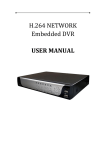
SMDVS8OPTI USER OPERATION MANUAL CONTENT INTRODUCTION .............................................................................................. 1 -PRECAUTIONS / FEATURES / RESTRICTION ABOUT AUDIO RECORDING SPECIFICATIONS ...............................................................................2-3 DVR 2 Camera 3 REMOTE CONTROL OPERATION ............................................................. 4 MOUSE OPERATION............................................................................... 5 ICON INDICATORS ………………………………………………………………………..5 OPERATION ……………………………………………………….........................6-12 - ON/OFF 6 - SUB-MENU 6 - MAIN MENU 6 - BASIC 6 - LIVE 7 - RECORD 8 - NETWORK 9 - Alarm 10 - Exception 10 - PTZ Configuration 11 - Preview 11 - USER 12 - BACKUP 12 - TOOLS 12 REMOTE VIEWING ………………………...…………………………………………....13 FAQ (Frequently Asked Questions) ….…………………….………………… 14-15 PACKAGE CONTENTS …………………………………………………………………... 16 Cell phone remote viewing referred to include CD in package INTRODUCTION Who would think this is possible, this 8 channel H.264 compression system w/6 cameras in kit, leave two out for your option, GO TO www.sumasmedia.com for choices. here we are offering you with most advanced and high up to 650 TV Line cameras and is not even offering in this market, multi function on data back up for whatever your convince at the time, reliable function for such an affordable pricing and the system is so simple to operate, the VGA/RCA connectors allows you to display on your TV and/or LCD monitor, built in network connector allow you have remote internet viewing and access, you can also monitor from your smart phones, and playback with H.323 compression superb high resolution. AUDIO RESTRICTION Audio recording is illegal in some states, such as California. So please check with your local law enforcement to confirm it’s allowed in your area, without violating the law. PRECAUTIONS For your safety, while using the DVR and to prolong device life, please pay attention to the following details: o o o o o o o When installing device, please comply with all the electric product safety criteria. Power and ground: Do not touch the power and DVR with a wet hand Do not spill liquid on DVR Do not put any object on DVR Please use soft dry cloth to clean DVR; do not use harmful chemicals. Please unplug power line from power source if the Device is not intended to be used for a long period of time. FEATURES 6 Day/Night High Resolution Digital Cameras 2 with audio H.264 compression Two USB interface, USB2.0 for data backup, USB1.1 for mouse operation. 1TB SATA HDD built-in Password sensitive secure operation up to 4 users Auto Data Rollover Recording Optimized four channel simultaneously playback Support remote live view, parameter setting and copy playback video via network. Cell phone remote viewing Data backup via USB port and DVDRW Motion detection USB mouse 1 SPECIFICATIONS DVR Specifications Item System Video Audio Alarm Picture and Storage Network and Monitoring Device Parameter Specification Language Multi language to choose from English/Spanish/Chinese/Dutch/French/Turkish/Russian/ Polish/Hungarian/Danish/Italian/Czech/Portuguese GUI Graphic menu (OSD Menu) Video in 8ch composite video input 1.0Vp-p,impedance75Ω, BNC Video out 1 VGA port,1 RCA port Video display 8ch:1/8channel switch Video system NTSC (30 frames/sec) Audio input 1-way Audio output 1-way Alarm Alarm sensor input; video dynamic detecting alarm; video loss alarm; disk space full alarm Alarm input 2-way (switching capacity) Alarm output 1-way (switching capacity) Picture compression H.264 Picture Resolution NTSC system: Display Resolution: 704 x 480 compressed resolution: 350 x 240 (NTSC for north America only) Data storage 1TB built-in SATA HDD storage, upgradable up to 2TB Network interface RJ45,10M/100M adaptive, support LAN, WAN & ADSL, dynamic IP networking Monitoring methods IE monitoring, phone monitoring, e-mail alert function Backup mode Support for USB, Optical Drive, and Network Backup Control Support for USB mouse, remote control, PTZ camera control (speed dome camera only) Software upgrade Support USB firmware upgrade Power Voltage input Dimensions and Weight Voltage input AC:110~240V Voltage output DC: 12V/5A Power Consumption 8W without HDD Working temperature +41°F ~ +122°F; humidity: <90% Storage temperature -4°F ~ + 158°F; humidity: <95% 12V DC 12V Dimension 130.75” x 2.50” x 11.25” (W x H x D) Weight (lbs) Net weight: 6.75 2 Gross weight: 7.85 SPECIFICATIONS Camera Specification Model SM-3058CE CCD Type Sony CCD Pixels NTSC 768H x 494v TV lines 650 TV lines Minimum Illumination 0LUX/F1.2 Lens 3.6mm 1/3 IR View Distance 40m Power Supply DC12V±5% Waterproof Yes Model SM-S\622AP/A CCD Type Sharp CCD Pixels NTSC 510H x 492v TV lines 420 TV lines Minimum Illumination 0LUX/F1.2 Lens 3.6mm 1/3 IR View Distance 20m Audio Yes Power Supply DC12V±5% Night Vision Yes 3 REMOTE CONTROL OPERATION Number Button 1 Power button 2 3 Alpha-numeric keys Fn 4 5 ●► ►● 6 +/- 7 Menu/Confirm 8 9 10 11 12 Timing PTZ INFO VGA Remarks Press 1X to turn unit on, press 2X to turn unit OFF Input numbers or characters; switch recording screen System Freeze Indicates fast rewind. 1x, 2x, 4x, 8x, 16x, 32x Indicates fast forward, 2x, 4x, 8x, 16x, 32x , ●► Press to go to the beginning of the clip that is currently playing. ►● Press to go to the last recorded clip. Volume control for audio recording and playback Enter into device menu and confirm setting Use key to move cursor Up/Down/Left/Right Enable or cancel timing recording Pan, Tilt and Zoom(speed dome camera) Press to show DVR information Disabled 13 16 channel view (disabled) 14 8 channel view 15 16 Mute button REC/STOP 17 18 Press to search the next recorded clip. 20 BACKSPACE (-) ESC (+) ALERT 21 SEARCH 22 DISPLAY 23 Clear 19 Enable and disables sound Start/stop video recording. The green round icon on the screen indicates manual recording state. ►Plays/stops the last recorded playback. Indicates two functions: pause or move to the next frame. It will appear in the image while it pause or is in frame step playing. Press to search the previous recorded clip. Backspace (-) Deletes inputted data ESC (+) Press to exit out of the menu Activates/deactivates alarm alert mode Press to enter search mode for recorded events Enables/disables display icons on the screen Press to silent the buzzer alarm 24 1 channel view 25 Quad channel display 4 MOUSE OPERATION The mouse is the primary input device for navigating system menus. NOTE: Unless otherwise noted, all system functions described in this manual are achieved using the mouse. To use a mouse with the system: 1) Connect the included USB mouse to the USB MOUSE port on the front of the unit. NOTE: The top USB port on the front panel is designed for data backup to a USB flash drive ONLY. Do not connect a USB flash drive to the bottom USB port on the rear panel. Connect a USB mouse to the bottom USB port on the front panel 2) Use the mouse buttons to perform the following: • Left-Button (1): Click to select a menu option; during live viewing in split-screen, double-click on a channel to view the selected channel in full-screen. Double-click the channel again to return to split-screen view • Right-Button (2): Click to open the Sub-Menu and/or to go back to the previous screen. • Wheel (3): No function. Icon Indicators The different symbols displayed on the screen, indicating different information. Some have no icon, some have icon. Please find the indicating meaning as below: Video recording symbol The green round icon indicates manual recording state Video recording symbol The yellow round icon indicates timing recording state. Playing symbol Indicates the recording is being played FF symbol Indicates fast forward, followed such as x2, indicate the fast forward speed FR symbol Indicates fast rewind. Followed such as x4, indicate the fast reward speed Timing symbol Indicates the video recorder is in timing state Alert symbol Indicates Alarm Alert mode is on USB Symbol Indicates the USB interface is connected Single frame symbol Indicates pause in single frame playing state. **/**/** Time display Playing time or recording time. 5 OPERATION Turning the unit on/off - Plug the included AC adapter to the back of DVR and plug the other end to a wall outlet, the unit will display white screen for few seconds before power on and boot up automatically. If the unit was already plugged in press the power button in front of the unit once to turn the DVR on. To turn the DVR off press the power button in front of the unit 2x to turn the DVR off. Note: Once the system has booted up, the display will show 8 channels screen view of all the cameras hooked up to the DVR. Sub Menu Using the mouse, right-click anywhere on the screen to bring up the sub-menu, the screen will now display the following: - SETTING: This will display the main menu - FILE LIST: This will display the recorded file list - SYSTEM INFO: This will play current system info (time/date, IP address, HDD capacity, etc…) - Alert: Enables alarm alert feature - Alert Stop: Disables alarm alert feature - TIMER: This enables the scheduled record time to activate. - TIMER STOP: This disables scheduled record time. - Clear: Disables alarm sound when pressed - RECORD: This enables manual recording. (Timer must be disabled) - RECORD STOP: This disables manual recording - PLAY FILES: This will play the recorded files starting from the oldest. - PTZ: Pan, Tilt, Zoom, in use with Speed dome cameras SUB-Menu Note: These functions can also be controlled using the remote control. (See page 4 for remote control functions) Main Menu - Select and click on “SETTING” while on the submenu, and key in the default password “88888888 (admin)”. - You can also press “MENU” on the remote to bring up the main menu. - The Main Menu will now show up and display the following: BASIC/LIVE/RECORD/NETWORK/ALARMSET/EXCEPTION/P.T.Z/PREVIEW/USER/BACKUP/TOOLS/EXIT Main Menu Password Input Window Time Adjust Screen On-Screen Numeric Keypad BASIC - Video Format: Click to select from NTSC or PAL. - Language: Click to select from the following: English/Spanish/Chinese/Dutch/French/Turkish/Russian/Polish/Hungarian/Danish/Italiano/Czech/Portuguese - Brightness: Click - / + to adjust screen brightness. - DVR ID: If you have multiple DVR’s, you can set a specific numeric ID for each one, up to 8 characters. - Enable System Log: This will log all the events - Panel Lock: Enable to lock the main menu; this will require a password every time the main menu is accessed. - Wait : Set the wait time under for the panel lock from 0min to 99mins - Screen Saver: This feature will turn off the screen with the selected time from 2,5,15,30mins, 1,5hrs, or never - Watermark: The watermark is half transparent. While it’s used, it will appear at the right corner of the screen. - Time Adjust: Click to enter time adjust screen. - To change the time and date settings: Simply click on the value that you want to change, and use the onscreen keypad to enter the desired value and click “X” on the keypad to close the keypad. - Repeat steps for the Year/Month/Day/Hour/Minutes/Seconds. - Click “Time Adjust” when finish to save the time and return to the “BASIC” main screen, click “OK” to exit to the “Main Menu”, and click “EXIT” to exit out of the main menu. Click “Yes” to save and exit the setup. - NTP: Network Time Protocol is used to synchronize the time of a computer client or server to another server or reference time source. Type in the desired NTP server and click on Active, input the Interval time from 0 to 999mins. - DST – select the appropriate time zone in your area, (for example Pacific Standard Time is -8). Then select what hour the time will change. 6 OPERATION continued LIVE Lets you customize camera names and setup Motion Detection. Camera name: To change camera name: Select which channel you want to change, click on the box with “01” to bring up the number pad click the box again to bring up the alpha-numeric pad (1= abc, 2= def… 0= @.-, etc…) and key in your desired name for channel 1 (upper/lower case indicator will appear on the bottom left corner) or click on “Select” and pick from a list. Brightness/Contrast/Hue/Sharpness: Click on -\+ on each option to change to your desired video outlook. Privacy Masking: Click on the circle next to privacy masking to enable/disable feature. Click on “Mask Area” to select the desired area to be masked (Up to 4 areas to be masked per channel). Click “Active” beside “Mark area 1” – “Mark area 4”, then select the “Area” To select the desired area to mask, simply click and hold then drag the mouse on the desired area to mask, right-click to exit. Repeat steps above for all the other “Mark area”. When done click on “Back” to return to the previous page. Mask Detection: Click the circle next to mask detection to enable/disable feature. - Sensitivity: Click on the box next to sensitivity and select from the following: Lowest/Lower/Normal/High/Highest. Trigger Record Click “ALARM” to view and edit the “Trigger Record”. Select which camera (1-8) you want to modify. Buzzer: Click to enable/disable buzzer sound when triggered. Alarm Upload: Click to enable/disable Send an e-mail: Click to enable/disable email notifications. Alarm Out: Click to enable/disable alarm feed. Prerecord: This determines how long the system will prerecord after a trigger, select prerecord time from 0 seconds to 60 seconds. Postrecord: This determines how long the unit will record after a trigger, select post record time from 0 seconds to 60 minutes Alarm Output Time: This determines how long the alarm output will sound after a trigger, select time from 0 seconds to 60 minutes. - VideoLoss: Click on the circle next to videoloss to enable/disable the video loss indicator. Click “Alarm” and follow the steps above for “Trigger Record” setup. - Motion Detection: Click on the circle next to “Motion Detection” to enable/disable feature. - To change sensitivity: Click on the box next to sensitivity and select from the following: Lowest/Lower/Normal/High/Highest. - Area: Click on “Area” to specify which areas you want to have the motion detection on and off. The selected areas will turn red (section An in image above). Trees, Flags and other constant moving objects should be grayed out to save hard drive space. Right click to exit. Click “Alarm” and follow the steps above for “Trigger Record” setup. - Copy To: You can copy the above settings to 1 or all the channels by the selecting the desired option under “Copy To” then click “Copy” to copy to the desired channel(s). Post-record time: This feature determines how long the unit will record after motion is detected. - Event Type: Click to select between “Normal” or “Alarm” - Postrecord Time: You can set from 0-second to 99-minutes. Repeat steps above for all other channels. Schedule Motion: Click on “Schedule Motion” to set specific time to activate motion detection. - Set schedule: Select the day you want under “Date” (Mon-Fri, Sat-Sun, Mon-Sun, Mon, Tue, Wed, Thur, Fri, Sat, Sun). - Start time: Click on the first box under “From” and to set the desired hour, click on the second on the same row to set the minutes. - End Time: Click on the first box under “To” to set the desired hour, click on the second box on the same row to set the minutes. - Repeat steps above for all other days. Once complete make sure to click on the box next to “Activate” on the bottom left of the window to activate motion detection schedule. Once done with all the changes: Click “OK” to confirm, then click “Exit” and select “Yes” to save all changes and to close main menu window. 7 OPERATION continued Record This will allow you to change the recording video quality and the recording schedule for each channel. Record Screen - Schedule Screen To change the recording video quality: Select the desired channel to be changed (1-8) Video Resolution: CIF (Common Image Format) is the only choice Video Quality: Select from Normal/Medium/Superior/Best/Custom. Type: Select from CBR (Constant Bit Rate) or VBR (Variable Bit Rate) Frame Rate: Select from 1 to 30 F/S (Frames per Second) Audio: You can enable audio recording by select “Y” or disable by selecting “N”. Secret Record: When enable, the display on selected camera will turn white on the monitor. Schedule Record - To Setup Scheduled Recording: Click on “Setup” next to “Schedule Record” the date and time setup screen will show up. - Under Date: Click to select day (Mon-Fri, Sat-Sun, Mon-Sun, Mon, Tues, Wed, Thur, Fri, Sat, Sun) - Start time: Click on the first box under “From” and to set the desired hour, click on the second box on the same row to set the minutes. - End Time: Click on the first box under “To” to set the desired hour, click on the second box on the same row to set the minutes. - Repeat steps above for all other days. Once complete make sure to click on “OK” to save changes. Copy To: Allows you to copy the same settings to 1 or all of the channels. To copy settings to 1 or all channels, select the desire channel from the pop-up screen (All, Ch1, Ch2, Ch3,…), then click on “Copy”, a message on the bottom left of the screen will say “Copy completely”. Custom Record Customize Quality - To customize record quality click “Customize Quality” “Video Quality Definition” screen will show up. - Under “Main Stream” key-in the desired quality specified by MB/Hr (megabytes per hour), for Best/Superior/Medium/Normal/Custom. - Under “Secondary Stream” key-in the desired quality specified by MB/Hr (megabytes per hour), for Best/Superior/Medium/Normal/Custom. - Default: To reset video quality configuration to factory defaults click on “Default”, then click “OK” to exit to the previous screen, click “OK” again to go to the main menu, and click “EXIT” and select “YES” to confirm save and exit. Note: The higher the video quality the more hard drive space it will take up. 8 OPERATION continued Network This will allow you to setup the network for remote viewing. (Internet Explorer 6.0 or higher required) IP Configuration Screen Port Configuration Screen Email Configuration Screen Static IP Setup To input the IP configuration, click on “IP Config:” and select “Static IP” Fill out all appropriate fields IP Address, Subnet Mask, Gateway, DNS. Click on “Port Config” and verify that all fields are filled out. (Control Port (3357), Video Stream (3358), Talkback Stream (3360), HTTP port (80). Note: When using a router, make sure all of these ports are properly forwarded/open to be able to view outside the local network. (Check router manual for port forwarding options). DHCP This will automatically configure and assign an IP address to the system. To view the assigned IP address, simply right click anywhere on the screen and select “SYSTEM INFO” ,or go to the main menu, select “TOOLS” and click on “Sys Information”. The IP address will view display towards the bottom or the screen. Once the IP address is acquired you can now start remote viewing from a local computer, by typing the IP address on the internet explorer search bar. Note: The DVR’s IP address might change if the DVR is rebooted or after a power failure. This network configuration is limited to local remote viewing. DDNS Setup (Use for non-static IP address) Click on “DDNS Config” to configure DNS settings. If you don’t have a registered domain name, please visit www.dyndns.com or www.no-ip.com to setup a free domain name and follow the free account setup. (make sure to select “.dyndns.org” or “.no-ip.org”) Once an account has been setup, click on “DDNS”. Click on the server and select “dyndns.org” or “no-ip.org” Under “Account”, input your account user name and under “PWD” input your password from www.dyndns.com or www.no-ip.com. Under “Hostname” enter the domain name you have created from www.dyndns.com or www.no-ip.com (no need include “.dyndns.org” or “.no-ip.org”). Click on “Activate” and then click on “OK” Click “OK” again to exit to the main menu, then click “EXIT” and confirm the “save and exit” Email Configuration From: Input the desired name you want the email to show up from. To: Input the desired email address you want to received the email(s) to. Cc: Input the desired email address that you want to have a carbon copy sent to. Smpt server: Input your emails SMTP server information Account: Input the email address that you are using to send out the emails. Password: Input your email password then click ok to exit email configuration. Click “OK” again to exit to the main menu, then click “EXIT” and confirm the “save and exit” Router Setup Input DNS info from www.dyndns.org or www.no-ip.com that you have created into the DDNS setup page on your router. You must enable port forwarding for the following ports (3356, 3357, 3358, 3359, 3360, and HTTP port 80). Once all the settings are inputted correctly make sure you save and reboot your router. Once the router has rebooted; open internet explorer browser on your computer and type the domain name you have registered with www.dyndns.org or www.no-ip.com (example http://sumasmedia.dyndns.org). Note: Different brands of routers will have different ways on how to enable port forwarding. Please check with your routers user manual to properly setup port forwarding. 9 OPERATION continued ALARM This will allow you to setup and configure your alarm settings. - - Alarm In: Click on the box to select “Alarm In1” or “Alarm In2”. Alarm Input Type: Click on the box and select from “NO” (If alarm input is connected to normal opened alarm), or “NC” (If the alarm input is connected to a normal closed alarm) - Alarm: Click to enter Trigger Record setup. - Trigger Record Click “ALARM” to view and edit the “Trigger Record”. Select which camera (1-8) you want to modify. Buzzer: Click to enable/disable buzzer sound when triggered. Alarm Upload: Click to enable/disable. This feature uploads the alarm image to a remote host. (Available when management host is connected.) The time of image upload depends on time of alarm upload. Send an e-mail: Click to enable/disable email notifications. Alarm Out: Click to enable/disable alarm feed. Prerecord: This determines how long the system will prerecord after a trigger, select prerecord time from 0seconds to 60 seconds Postrecord: This determines how long the unit will record after a trigger, select post record time from 0 seconds to 60 minutes Alarm Output Time: This determines how long the alarm output will sound after a trigger, select time from 0 seconds to 60 minutes. Copy to: This feature will enable you to copy the alarm settings (1 or 2) to the other alarm input (1 or 2). To copy simply select the alarm input you want to copy to, then click on “Copy” Alarm Out: There is only 1 alarm output to select. Alarm Output Type: Click on the box and select from “NO” (If alarm input is connected to normal opened alarm), or “NC” (If the alarm input is connected to a normal closed alarm). Copy To: This feature is disabled due only 1 alarm output. Alert Delay: Enter the alert delay time from 1 second to 99 minutes. Schedule Alert To Setup Scheduled Alert: Click on “Schedule Alert” the date and time setup screen will show up. Operation: Click the box under operation and select operation type Alarm On/Alarm Off/Alarm Out. Date: Click the box under date to select day (Mon-Fri, Sat-Sun, Mon-Sun, Mon, Tues, Wed, Thur, Fri, Sat, Sun) - Start time: Click on the first box under “From” and to set the desired hour, click on the second box on the same row to set the minutes. End Time: Click on the first box under “To” to set the desired hour, click on the second box on the same row to set the minutes. Repeat steps above for all other days. Once complete make sure to click on “OK” to save changes. EXCEPTION This feature will alert you when the either the hard drive is full or has an error. - Type: Select “HDD Full” or “HDD Error” - Buzzer: Check box to enable or disable buzzer sound. - Alarm Upload: Check box to enable or disable alarm uploads. - Send an email: Check box to enable or disable email notifications. - Alarm out: Check box to enable or disable alarm out. When done click “OK” to exit to the mail menu then “EXIT” and select “Yes and exit” to confirm save. 10 OPERATION continued P.T.Z. Configuration (Speed dome camera only – not included, check for availability at www.sumasmedia.com) Set the channel number of decoder, including velocity, data bit, stop bit, checkout and stream control, in serial port device menu. The values of these items must match the connected serial device. The default values are: 8 data bits, 1 stop bit, none checkout bit and hardware stream control. These data cannot be revised by customer. - Port: Use RS485 on the back of the unit. Baud Rate: Select from: 19200, 9600, 4800, 2400, and 1200. The selected must match with the protocol and parameters of the decoder. Devise type: Select from No Device/PTZ Decoder/Keyboard. The device is applicable when the option matches with the protocol and parameters of the decoder. Channel: Select the channel that will have P.T.Z. (Ch1 – Ch8) PTZ Protocol: Select type of decoder protocol. The following decoder protocols are present in the program, including Panasonic, LLW, Pelco-D, Pelco-P, Lilin, Neon, Pelco-D YA, Pelco-D SFD, Pelco-P MK, Pelco-P JJ, Pelco-D ZT and Samsung. Note: Different protocols can be used for different channels. - - PTZ Address: Input the address of the decoder connected to the selected screen. The address ID must be consistent with the address of the front-end decoder, or it will lead to failure of control. The address ID is set by user. PTZ Step: Control the speed parameters when moving the PTZ. The bigger the step length is, the higher the speed will be. Present positions: This parameter is for setting of speed dome camera. The location of the camera, the focus, aperture and zoom should be present and memorized, and a number should be used to mark the setting. Present point number: Input a number from 00 to 63. Adjust location: Press “Adjust” to enter control status and adjust the location of the dome by direction buttons. Press Menu button to return. Save: To save current setting to the present point number. Set your required present points one by one. Get: This feature will retrieve what the current settings from the camera. Keyboard: Select the appropriate keyboard type (L.C., Pinerve, Samlink, Mianvan) Copy to: This feature will enable you to copy the PTZ settings 1 or all the channels. To copy simply select the channel you want to copy to, then click on “Copy” When done click “OK” to exit to the mail menu then “EXIT” and select “Yes and exit” to confirm save. Preview This feature will cycle through the different channels automatically when nobody is operating the unit. - Interval: Input the desired interval time from 0-99 seconds. Cyclic Screen Mode: Select between “One Chan” this will cycle one channel at a time, “Four Chan” this will cycle 4 channels at a time, “All Chan” when activated in conjunction with “One Chan” or “Four Chan” or both, the cycle will include all channels in the mix. Activate: Make sure to check this box to activate this feature. When done click “OK” to exit to the mail menu then “EXIT” and select “Yes and exit” to confirm save. 11 OPERATION continued USER This will allow you to change the default password (admin “88888888”, Operator 1-3 “66666666”) to your desired password, and also add up to 4 different users (Admin, Operator 1, 2 and 3). Change/Set Password To change password click on “USER” from the main menu. Select the which user you want to change/set the password (Admin, Operation 1, 2, or 3) Enter the current password under “Current PWD” (default password is “66666666” or “88888888”) Under “New PWD” enter your new password and enter again in “Confirm New PWD” Authorization Setting: Select which setting the operator can access (Basic/Live/Record/Network/Alarm Set/Exception/PTZ/Preview/USER/Backup/Tools). Check “Authorization Check” if you want the password to be prompted every time you want to access the system “Setting”. Repeat steps above for all the other users. When trying to access the menu, the unit will ask for a password, the entered password will determine which user is logged on. Note: Password can be up to 8 digits. Make sure you write your password in a safe place. Only admin can change the password. When done click “OK” to exit to the mail menu then “EXIT” and select “Yes and exit” to confirm save. BACKUP This will allow you to backup recorded events on the DVR to a USB flash drive, an external HDD or through the DVDRW drive. (It will also take a minute to start up). - To start backup enter the correct time and date you want to backup (From/To) Select what type of event under “By Event Type” Normal/Alarm/All Select the file size “Full” or “Original” Backup Channel: Select which channel you want to backup (1-8) and press OK Playback Screen Mode will allow you to select how many and which channel(s) you want the playback to show on. Select from 1 Chan, 2 Chan, or 4 Chan, and then select which channels 1-8, once selected, press “Playback” to view the recorded event. (Unit will not play the record event). You can also click on “List and Search” to view and select from list of recorded events on the selected time frame. Right-click anywhere on the screen to bring up the playback controls (PLAY, STOP, FB, FF, PREV, NEXT, CHAN). Once confirmed, press “STOP” to go back to the Backup menu and click on “BACKUP” and select the drive you want to backup to and click “OK”. - Note: Time of backup will vary depending on the size of the file(s) and media type. When backing up with the DVDRW drive make sure that the burning process completely finishes (when your devise’s indicator light turn off) before removing the disc, removing the disc prematurely may result incomplete transfer and the disc will not be readable by your PC. TOOLS This will give you access to the following: - Load Default: This will reset the DVR to the factory settings. - Update Firmware: Use to update the firmware of the system. - HDD Mng: Use to format or do data recovery. Data Recovery is ONLY used if the hard drive has some bad sectors. The system will try to recover any file in the bad sector. Note: Once hard drive is formatted all data will be lost. - System Log: Will list all of the system logs. (System Log must be enable in the “Basic” menu). Simply enter the dates (From-To) you want to view the logs from and click “Log list” System Information: Shows all of the system configurations. System Mng: You can reboot or power off the system in this section. 12 REMOTE VIEWING Remote viewing requires Internet Explorer (IE) 6.0 or higher running on Window XP or higher. To start - - remote viewing: Make sure that network configuration is properly setup. Open IE and type in the IP address for (xxx.xxx.xxx.xxx) on the address bar. (Fig. 1) For non static IP type-in the domain name you have registered from www.dyndns.com or www.no-ip.com. Active X attention bar should pop-up. Click on the Active X attention bar and select run/install. Active X controller must be installed in able to run remote viewing. If “Active X” bar does not pop-up and log-in screen does not come up, you must enable Active X in IE internet options (Fig.2) and try again. Enter the password when prompt and click OK. Default password is “88888888” Once logged in, quad view should automatically start showing all the active camera views. (Fig.3) Fig. 1 Fig. 2 Fig. 3 Control configurations for remote viewing. Logout: To log off remote viewing. View: To view cameras. Playback: To playback recorded events. Log: To view system logs. DVR configuration: To enter DVR configuration. (Basic info, Channel config, and Network config). Local setting: To specify local storage/capture/save paths. Camera channels: Double-click to enable/disable camera channel Viewing pane: Live and Playback viewing window. Full screen view: To view selected channel in full screen mode. Quad screen view: To switch from full screen view to quad view. 8 channel view: To switch from full or quad view to 8 channel view. Stop/Live: To stop viewing or playback, click to view live view when stopped. Capture: To take screen shot of selected camera channel. (Screenshot is save on the local hard drive) Record: To start recording what’s currently on the screen to your local hard drive. Brightness, Hue, Contrast, Sharpness: Adjust up/down to get the desired video settings. Brightness, Hue, Contrast, Sharpness Reset: Resets all video setting to default. PTZ Controls: ▲▼◄► Up/Down/Left/Right or auto cruise (center button) Channel Select: Select which channel has the PTZ Speed Dome camera. Assistant 1 & 2: Some speed dome cameras have extra features (Wiper and Sun shade) that can be controlled by these 2 buttons. Preset Setting: Select the preset angle of the speed dome camera. Preset: Click after setting the preset setting to confirm angle setup. Get: Click to get the current angle settings Focus, Zoom, Iris: Press to get the desired settings. Cell Phone Viewing This DVR also supports remote viewing via cell phone. Support cell phones are iPhone, Nokia, Motorola, Samsung, HP, etc… Please refer to the included CD for instructions and cell phone software. 13 FAQ (Frequently Asked Questions) If your problem is not listed below, please call our toll-free number for more support. 1. Question: DVR will not power up? Answer: Check the adaptor input to the DVR. Check the power supply line connection going to the wall outlet. Test another device on the wall socket to make sure there is power. 2. Question: DVR is rebooting automatically or stopped after starting the DVR for several minutes? Answer: Instability or low input voltage. Bad sector on the hard drive or the hard drive has gone bad. Power supply output is not enough or wrong voltage power supply. Over heating, dusty, or high humidity environment to operate. 3. Question: No output of signal channel, multi channel or all channel video, blue screen? Answer: Please check camera’s AC adaptor connection. Please check the camera’s BNC connection on the back of the DVR and to the camera. Make sure they are both locked in place. Try swapping the camera connections to determine if there is a defective camera. 4. Question: DVR cannot record after startup. Answer: Make sure the power adaptor is DC 12V. Confirm the HDD is formatted. To format HDD go to “Tools” then “HDD Mng” The HDD has gone bad. Go to the system info to check if the unit is recognizing the HDD. Scheduled Recording is enabled. Disable Scheduled Recording. 5. Question: Video is flickering, lines across the screen on each channel; display is distorted or black and white? Answer: Check and make sure the LCD monitor and the VGA cable are in good working condition. Make sure the system is set to NTSC NOT PAL (see Basic setup on page 6). The recommended monitor display screen resolution is at least 800 x 600. Reset the system (see page 8). 6. Question: System time is not correct? Answer: A system Reset was done. Redo time setup. (see page 6) Wrong setting or user did not click "Time Adjust" to confirm. (see page 6) 7. Question: Why the “Record Stop” by clicking the right mouse button does not work, how to stop recording? Answer: The “Record Stop” by right mouse button will only work with Manual recording. This cannot stop recording when the DVR is on “scheduled recording” mode. You must click on “Timer Stop” first to stop recording. If the recording does not stop, click on “Record Stop” to stop the recording. 14 FAQ (Frequently Asks Questions) cont. 8. Question: Motion detection is not working properly? Answer: Motion detection is not enabled. (see page 7) The setting of motion detection area is not correct. (see page 7 for setup) Sensitivity is too low. 9. Question: USB backup error Answer: The data exceeds the capacity of backup device The backup device is incompatible or not formatted properly (FAT/FAT32). The backup device is damaged. USB device plugged into the wrong port. (see page 5) External CDRW/DVDRW USB backup usually takes about a minute to start. 10. Question: Remote control cannot work? Answer: The distance of remote control is too far or the angle is bad Remote control battery run out, replace batteries. 11. Question: WEB cannot login? Answer: Please check the network to see if it is connected. Ping xxx.xxx.xxx.xxx (DVR IP) to check if the Internet is linked properly. Recommended to use Internet Explorer browser v6.0 or higher running on Windows XP or higher operating system. ActiveX control has been blocked or disabled. Enable or disable the Active X control in the options menu in internet explorer. 12.Question: There is no picture or picture is not clear when you preview the recording or playback the recording via IE. Answer: Restart browser and log back in to the DVR. Restart the DVR by going to “Tools” in the main menu then click on “System Mng” and click on “Restart DVR” 13. Question: The mouse is not detected or not working properly. Answer: Mouse is defective or broken. Mouse is plugged in the wrong port. Make sure the mouse is plugged in the USB mouse port. (see page 5) 14. Question: No picture on selected channels, Camera not displaying picture, when there’s no light the color of the picture looks weird. Answer: Camera cable are loose or disconnected, Camera power cable not connected or defective. Night vision color on a CCD camera is different than a normal camera. 15. Question: A humming sound and vibration coming from the system. Answer: This is normal, the humming and vibration is coming from hard drive while it’s spinning. 16.Question: Cannot login system when trying to remote view, IE browser stuck at loading or error message on the screen. Answer: Check and make sure all the network settings on the DVR including the DDNS setting if you are using non-static IP. Also check you domain registration to make sure it’s not expired. 15 PACKAGE CONTENT DVR 4 x Camera with bracket 4 X 80’ Power/Video Cable 2 X 60’ Power/Video/Audio Cable User Manual Software CD DVR 12V 5A DC Power supply Quick start guide USB Mouse 16 2 x Camera with audio 6 x cameras 12Volt 2A Power supply Remote Control 6 X Camera Mounting Kit