1
M68ICS08SOM/D
June 2000
M68ICS08
68HC08 In-Circuit Simulator
Operator’s Manual
©P&E Microcomputer Systems, Inc., 1999; All Rights Reserved
Purchase Agreement
P&E Microcomputer Systems, Inc. reserves the right to make changes without further notice to any products herein to
improve reliability, function, or design. P&E Microcomputer Systems, Inc. does not assume any liability arising out of
the application or use of any product or circuit described herein.
This software and accompanying documentation are protected by United States Copyright law and also by
International Treaty provisions. Any use of this software in violation of copyright law or the terms of this agreement
will be prosecuted.
All the software described in this document is copyrighted by P&E Microcomputer Systems, Inc. Copyright notices
have been included in the software.
P&E Microcomputer Systems authorizes you to make archival copies of the software and documentation for the sole
purpose of back-up and protecting your investment from loss. Under no circumstances may you copy this software or
documentation for the purpose of distribution to others. Under no conditions may you remove the copyright notices
from this software or documentation.
This software may be used by one person on as many computers as that person uses, provided that the software is
never used on two computers at the same time. P&E expects that group programming projects making use of this
software will purchase a copy of the software and documentation for each user in the group. Contact P&E for volume
discounts and site licensing agreements.
P&E Microcomputer Systems does not assume any liability for the use of this software beyond the original purchase
price of the software. In no event will P&E Microcomputer Systems be liable for additional damages, including any
lost profits, lost savings or other incidental or consequential damages arising out of the use or inability to use these
programs, even if P&E Microcomputer Systems has been advised of the possibility of such damage.
By using this software, you accept the terms of this agreement.
Portions of this manual are reprinted with permission, from M68ICS08RKSOM/D, Copyright 1999; Motorola, Inc.
MS-DOS & Windows are registered trademarks of Microsoft Corporation. Motorola is a registered trademark of
Motorola, Inc. IBM is a registered trademark of IBM corporation.
P&E Microcomputer Systems, Inc.
P.O. Box 2044
Woburn, MA 01888
617-353-9206
www.pemicro.com
Manual version 1.05
P&E
CHAPTER 1
Microcomputer
Systems, Inc.
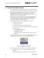
INTRODUCTION
1.1
OVERVIEW ................................................................................................................. 1-1
1.2
ICS08 INTERFACE SOFTWARE PACKAGE........................................................... 1-2
1.2.1
Software Requirements............................................................................................................... 1-2
1.3
ICS08 PACKAGE FEATURES ................................................................................... 1-2
1.4
ABOUT THIS OPERATOR’S MANUAL................................................................... 1-4
1.4.1
Chapter Organization.................................................................................................................. 1-4
1.4.2
Document Conventions .............................................................................................................. 1-5
1.5
SOFTWARE QUICK START INSTRUCTIONS........................................................ 1-5
1.6
MC68HC908 SECURITY FEATURE ......................................................................... 1-8
1.7
CUSTOMER SUPPORT ............................................................................................ 1-10
CHAPTER 2
SOFTWARE INSTALLATION AND INITIALIZATION
2.1
OVERVIEW ................................................................................................................. 2-1
2.2
THE ICS08 SOFTWARE COMPONENTS................................................................. 2-1
2.3
2.4
2.2.1
WinIDE Editor............................................................................................................................ 2-1
2.2.2
CASM08Z Assembler ................................................................................................................ 2-2
2.2.3
ICS08Z In-Circuit Simulator Software....................................................................................... 2-2
2.2.4
ICD08SZ In-Circuit Debugger ................................................................................................... 2-3
2.2.5
PROG08SZ FLASH Programmer .............................................................................................. 2-3
INSTALLING THE ICS08 SOFTWARE PACKAGE ................................................ 2-3
2.3.1
Installation Steps......................................................................................................................... 2-3
2.3.2
Starting the ICS08 Software ....................................................................................................... 2-4
TARGET CONNECTION AND SECURITY DIALOG ............................................. 2-5
2.4.1
TARGET HARDWARE TYPE ................................................................................................. 2-5
2.4.2
PC SERIAL PORT CONFIGURATION ................................................................................. 2-11
2.4.3
TARGET MCU SECURITY BYTES ...................................................................................... 2-11
2.4.4
STATUS ................................................................................................................................... 2-12
2.4.5
ADDITIONAL DIALOG BUTTONS...................................................................................... 2-15
CHAPTER 3
THE WinIDE USER INTERFACE
3.1
OVERVIEW ................................................................................................................. 3-1
3.2
WINDOWS INTEGRATED DEVELOPMENT ENVIRONMENT ........................... 3-1
3.3
WinIDE MAIN WINDOW........................................................................................... 3-2
M68ICS08SOM/D
iii
P&E
3.4
Microcomputer
Systems, Inc.
3.3.1
Main Window Functions ............................................................................................................ 3-2
3.3.2
Main Window Components ........................................................................................................ 3-3
GETTING STARTED .................................................................................................. 3-4
3.4.1
Prerequisites for Starting the WinIDE Editor ............................................................................. 3-4
3.4.2
Starting the WinIDE Editor ........................................................................................................ 3-4
3.4.3
Opening Source Files.................................................................................................................. 3-4
3.4.4
Navigating in the WinIDE Editor ............................................................................................... 3-5
3.4.5
Using Markers............................................................................................................................. 3-6
3.5
COMMAND-LINE PARAMETERS ........................................................................... 3-8
3.6
WinIDE TOOLBAR ..................................................................................................... 3-8
3.7
WinIDE MENUS ........................................................................................................ 3-10
3.8
WinIDE FILE OPTIONS............................................................................................ 3-12
3.9
3.8.1
New File.................................................................................................................................... 3-12
3.8.2
Open File................................................................................................................................... 3-13
3.8.3
Save File ................................................................................................................................... 3-13
3.8.4
Save File As .............................................................................................................................. 3-14
3.8.5
Close File .................................................................................................................................. 3-14
3.8.6
Print File ................................................................................................................................... 3-14
3.8.7
Print Setup................................................................................................................................. 3-15
3.8.8
Exit............................................................................................................................................ 3-15
WinIDE EDIT OPTIONS ........................................................................................... 3-15
3.9.1
Undo.......................................................................................................................................... 3-16
3.9.2
Redo .......................................................................................................................................... 3-16
3.9.3
Cut............................................................................................................................................. 3-17
3.9.4
Copy.......................................................................................................................................... 3-17
3.9.5
Paste .......................................................................................................................................... 3-17
3.9.6
Delete ........................................................................................................................................ 3-17
3.9.7
Select All................................................................................................................................... 3-17
3.10 WinIDE ENVIRONMENT OPTIONS....................................................................... 3-18
iv
3.10.1
Open Project ............................................................................................................................. 3-19
3.10.2
Save Project .............................................................................................................................. 3-19
3.10.3
Save Project As ......................................................................................................................... 3-20
3.10.4
Close/New Project .................................................................................................................... 3-20
3.10.5
Setup Environment ................................................................................................................... 3-20
3.10.6
Setup Fonts ............................................................................................................................... 3-31
3.10.7
WinIDE SEARCH OPTIONS .................................................................................................. 3-33
3.10.8
Find ........................................................................................................................................... 3-33
3.10.9
Replace...................................................................................................................................... 3-34
M68ICS08SOM/D
P&E
Microcomputer
Systems, Inc.
3.10.10 Find Next .................................................................................................................................. 3-35
3.10.11 Go to Line ................................................................................................................................. 3-35
3.11 WinIDE WINDOW OPTIONS .................................................................................. 3-36
3.11.1
Cascade ..................................................................................................................................... 3-37
3.11.2
Tile............................................................................................................................................ 3-38
3.11.3
Arrange Icons ........................................................................................................................... 3-39
3.11.4
Minimize All............................................................................................................................. 3-40
3.11.5
Split........................................................................................................................................... 3-41
CHAPTER 4
CASM08Z ASSEMBLER INTERFACE
4.1
OVERVIEW ................................................................................................................. 4-1
4.2
CASM08Z ASSEMBLER USER INTERFACE.......................................................... 4-2
4.3
ASSEMBLER PARAMETERS ................................................................................... 4-3
4.4
ASSEMBLER OUTPUTS ............................................................................................ 4-4
4.5
4.6
4.7
4.8
4.4.1
Object Files................................................................................................................................. 4-4
4.4.2
Map Files .................................................................................................................................... 4-4
4.4.3
Listing Files ................................................................................................................................ 4-4
4.4.4
Error Files ................................................................................................................................... 4-5
4.4.5
Files from Other Assemblers ...................................................................................................... 4-6
ASSEMBLER OPTIONS ............................................................................................. 4-6
4.5.1
Operands and Constants ............................................................................................................. 4-6
4.5.2
Comments ................................................................................................................................... 4-7
ASSEMBLER DIRECTIVES....................................................................................... 4-8
4.6.1
BASE .......................................................................................................................................... 4-8
4.6.2
Cycle Adder ................................................................................................................................ 4-8
4.6.3
Conditional Assembly .............................................................................................................. 4-10
4.6.4
INCLUDE................................................................................................................................. 4-10
4.6.5
MACRO.................................................................................................................................... 4-11
LISTING DIRECTIVES............................................................................................. 4-12
4.7.1
Listing Files .............................................................................................................................. 4-12
4.7.2
Labels........................................................................................................................................ 4-14
PSEUDO OPERATIONS ........................................................................................... 4-15
4.8.1
Equate (EQU) ........................................................................................................................... 4-15
4.8.2
Form Constant Byte (FCB)....................................................................................................... 4-16
4.8.3
Form Double Byte (FDB)......................................................................................................... 4-16
4.8.4
Originate (ORG) ....................................................................................................................... 4-16
4.8.5
Reserve Memory Byte (RMB) ................................................................................................. 4-16
M68ICS08SOM/D
v
P&E
4.9
Microcomputer
Systems, Inc.
ASSEMBLER ERROR MESSAGES......................................................................... 4-17
4.10 USING FILES FROM OTHER ASSEMBLERS ....................................................... 4-19
CHAPTER 5
ICS08Z IN-CIRCUIT SIMULATOR
5.1
OVERVIEW ................................................................................................................. 5-1
5.2
ICS08Z DESCRIPTION............................................................................................... 5-1
5.3
5.2.1
ICS08 Simulation Speed ............................................................................................................. 5-2
5.2.2
System Requirements for ICS08Z Software............................................................................... 5-2
5.2.3
File Types and Formats............................................................................................................... 5-2
STARTUP AND PARAMETERS................................................................................ 5-4
5.3.1
Startup Parameters ...................................................................................................................... 5-4
5.4
ESTABLISHING COMMUNICATION ...................................................................... 5-7
5.5
ICS08Z WINDOWS ..................................................................................................... 5-7
5.6
CODE WINDOWS....................................................................................................... 5-9
5.7
5.6.1
To Display the Code Windows Shortcut Menus ........................................................................ 5-9
5.6.2
Code Window Shortcut Menu Functions.................................................................................. 5-10
5.6.3
Code Window Keyboard Commands ....................................................................................... 5-11
VARIABLES WINDOW ........................................................................................... 5-11
5.7.1
Displaying the Variables Shortcut Menu.................................................................................. 5-11
5.7.2
Variables Window Shortcut Menu Options.............................................................................. 5-12
5.7.3
Variables Window Keyboard Commands ................................................................................ 5-12
5.8
MEMORY WINDOW ................................................................................................ 5-13
5.9
STATUS WINDOW................................................................................................... 5-14
5.10 CPU08 WINDOW ...................................................................................................... 5-17
5.10.1
Changing Register Values ........................................................................................................ 5-17
5.10.2
CPU08 Window Keyboard Commands .................................................................................... 5-18
5.11 CYCLES WINDOW................................................................................................... 5-18
5.12 STACK WINDOW..................................................................................................... 5-18
5.12.1
Interrupt Stack........................................................................................................................... 5-20
5.12.2
Subroutine Stack ....................................................................................................................... 5-20
5.13 TRACE WINDOW..................................................................................................... 5-21
5.14 BREAKPOINT WINDOW......................................................................................... 5-21
vi
5.14.1
Adding a Breakpoint ................................................................................................................. 5-23
5.14.2
Editing a Breakpoint ................................................................................................................. 5-23
5.14.3
Deleting a Breakpoint ............................................................................................................... 5-24
M68ICS08SOM/D
P&E
5.14.4
Microcomputer
Systems, Inc.
Removing All Breakpoints ....................................................................................................... 5-24
5.15 REGISTER BLOCK WINDOW ................................................................................ 5-25
5.16 ENTERING DEBUGGING COMMANDS ............................................................... 5-26
5.17 ICS08Z TOOLBAR .................................................................................................... 5-26
5.18 ICS08Z MENUS......................................................................................................... 5-28
5.19 FILE OPTIONS .......................................................................................................... 5-30
5.19.1
Load S19 File............................................................................................................................ 5-30
5.19.2
Reload Last S19........................................................................................................................ 5-31
5.19.3
Play Macro................................................................................................................................ 5-31
5.19.4
Record Macro ........................................................................................................................... 5-32
5.19.5
Stop Macro ............................................................................................................................... 5-32
5.19.6
Open Logfile............................................................................................................................. 5-32
5.19.7
Close Logfile ............................................................................................................................ 5-34
5.19.8
Exit............................................................................................................................................ 5-34
5.20 ICS08Z EXECUTE OPTIONS................................................................................... 5-35
5.20.1
Reset Processor......................................................................................................................... 5-35
5.20.2
Step ........................................................................................................................................... 5-35
5.20.3
Multiple Step ............................................................................................................................ 5-35
5.20.4
Go ............................................................................................................................................. 5-36
5.20.5
Stop ........................................................................................................................................... 5-36
5.20.6
Repeat Command ..................................................................................................................... 5-36
5.21 ICS08Z WINDOW OPTIONS ................................................................................... 5-36
5.21.1
Open Windows ......................................................................................................................... 5-37
5.21.2
Change Colors .......................................................................................................................... 5-37
5.21.3
Reload Desktop......................................................................................................................... 5-38
5.21.4
Save Desktop ............................................................................................................................ 5-38
5.22 ICS08Z DEBUGGING COMMANDS ...................................................................... 5-38
5.23 ICS08Z DEBUGGING COMMAND SYNTAX ....................................................... 5-39
5.24 COMMAND SET SUMMARY ................................................................................. 5-40
5.24.1
Argument Types ....................................................................................................................... 5-40
5.24.2
Command Summary ................................................................................................................. 5-41
CHAPTER 6
PROG08SZ FLASH PROGRAMMER
6.1
OVERVIEW ................................................................................................................. 6-1
6.2
STARTUP AND PARAMETERS................................................................................ 6-2
6.3
PROGRAMMING COMMANDS ............................................................................... 6-4
M68ICS08SOM/D
vii
P&E
6.4
Microcomputer
Systems, Inc.
6.3.1
BM – Blank-check Module......................................................................................................... 6-4
6.3.2
CM – Choose Module .08P......................................................................................................... 6-4
6.3.3
EM – Erase Module .................................................................................................................... 6-4
6.3.4
PB – Program Bytes.................................................................................................................... 6-4
6.3.5
PM – Program Module ............................................................................................................... 6-5
6.3.6
SM – Show Module .................................................................................................................... 6-5
6.3.7
SS – Specify S-record ................................................................................................................. 6-5
6.3.8
UM – Upload Module................................................................................................................. 6-5
6.3.9
UR – Upload Range.................................................................................................................... 6-5
6.3.10
VM – Verify Module .................................................................................................................. 6-5
6.3.11
VR – Verify Range ..................................................................................................................... 6-6
6.3.12
QU – Quit.................................................................................................................................... 6-7
6.3.13
RE – Reset Chip.......................................................................................................................... 6-7
6.3.14
HE – Help ................................................................................................................................... 6-7
PROGRAMMING EXAMPLE .................................................................................... 6-7
CHAPTER 7
ICD08SZ IN-CIRCUIT DEBUGGER
7.1
OVERVIEW ................................................................................................................. 7-1
7.2
MON08 DEBUGGING LIMITATIONS AND TIPS................................................... 7-1
7.2.1
Limitations .................................................................................................................................. 7-1
7.2.2
Tips ............................................................................................................................................. 7-2
7.3
STARTUP AND PARAMETERS................................................................................ 7-4
7.4
USER INTERFACE ..................................................................................................... 7-6
7.5
7.4.1
Status Window ............................................................................................................................ 7-6
7.4.2
Code Window ............................................................................................................................. 7-7
7.4.3
Variables Window .................................................................................................................... 7-10
7.4.4
Memory Window ...................................................................................................................... 7-11
7.4.5
Change Window Colors Window ............................................................................................. 7-12
7.4.6
CPU08 Window ........................................................................................................................ 7-12
DEBUGGING COMMANDS .................................................................................... 7-14
7.5.1
Syntax and Nomenclature ......................................................................................................... 7-14
7.5.2
Command Recall....................................................................................................................... 7-15
7.5.3
Command Set Summary ........................................................................................................... 7-15
CHAPTER 8
8.1
viii
DEBUGGING COMMAND SET
COMMAND DESCRIPTIONS .................................................................................... 8-1
M68ICS08SOM/D
P&E
Microcomputer
Systems, Inc.
APPENDIX A S-RECORD INFORMATION
A.1 OVERVIEW ................................................................................................................ A-1
A.2 S-RECORD CONTENT .............................................................................................. A-1
A.3 S-RECORD TYPES .................................................................................................... A-2
A.4 S-RECORD CREATION ............................................................................................ A-3
A.5 S-RECORD EXAMPLE.............................................................................................. A-4
A.5.1
The S0 Header Record............................................................................................................... A-4
A.5.2
The First S1 Record ................................................................................................................... A-5
A.5.3
The S9 Termination Record ...................................................................................................... A-6
A.5.4
ASCII Characters....................................................................................................................... A-6
APPENDIX B
M68ICS08SOM/D
GLOSSARY
ix
P&E
x
Microcomputer
Systems, Inc.
M68ICS08SOM/D
P&E
Microcomputer
Systems, Inc.
CHAPTER 1
INTRODUCTION
1.1
OVERVIEW
This chapter provides an overview of Motorola’s M68ICS08 in-circuit
simulator packages, and a quick-start guide for setting up a development
project.
The ICS packages (e.g., RKICS, GPICS) are stand-alone development and
debugging aids for designers using various MC68HC908 microcontroller unit
(MCU) devices. Each package contains both the hardware and software needed
to develop and simulate source code for, and to program, one type of Motorola
MC68HC908 microcontroller. For example, the RKICS contains the
M68ICS08RK2 (hardware) and ICS08RK (software), which allow the user to
develop for Motorola’s MC68HC908RK2 microcontroller. Refer to the proper
M68ICS08 IN-CIRCUIT SIMULATOR HARDWARE OPERATOR’S
MANUAL for detailed information about your specific M68ICS08 hardware.
The ICS hardware and software form a complete simulator and limited realtime I/O (input/output) emulator for a particular MC68HC908 MCU device.
•
With the ICS08Z in-circuit simulator, the ICS can be used to input/
output signals from the simulator engine.
•
With the ICD08SZ software, the ICS can be used as a limited realtime emulator.
•
With the PROG08SZ software, the ICS can be used to program MCU
FLASH memory.
Use the ICS package with any IBM Windows 95, Windows 98, or Windows
NT-based computer with a serial port.
M68ICS08SOM/D
1-1
P&E
CHAPTER 1 – INTRODUCTION
1.2
Microcomputer
Systems, Inc.
ICS08 INTERFACE SOFTWARE PACKAGE
Windows-optimized software components, in this example collectively
referred to as the ICS08RK software, include:
•
WINIDE.EXE
—
•
CASM08Z.EXE
—
•
ICS08RKZ.EXE* —
In-circuit/stand-alone simulator software for the
MC68HC908RK2 MCU
•
PROG08SZ.EXE —
FLASH memory programming software
•
ICD08SZ.EXE
—
Integrated development environment (IDE)
software interface to the MC68HC908-based
hardware for editing and performing software or
in-circuit simulation
CASM08Z command-line cross-assembler
Limited, real-time, in-circuit debugging software
*If your package is for a different MCU part, substitute the name of your
part for RK.
Note: In this documentation, the part number ICS08Z will be understood to refer to
the In-Circuit Simulator component of the software package, while ICS08 will
refer to the entire software package.
1.2.1
Software Requirements
The ICS08 software requires this minimum hardware and software
configuration:
1.3
•
An IBM-compatible host computer running Windows 95, Windows 98
or Windows NT operating system
•
Approximately 5 MBytes of available random access memory (RAM)
and 5 MBytes of free disk space
•
A serial port for communications between the ICS board and the host
computer
ICS08 PACKAGE FEATURES
The ICS08 package is a low-cost development system that supports editing,
assembling, in-circuit simulation, in-circuit emulation, and FLASH memory
programming. Its features include:
•
•
•
1-2
Editing with WinIDE
Assembling with CASM08Z
FLASH memory programming with PROG08SZ
M68ICS08SOM/D
P&E
Microcomputer
Systems, Inc.
M68ICS08SOM/D
CHAPTER 1 – INTRODUCTION
•
In-circuit and stand-alone simulation of a particular MC68HC908
MCU with ICS08Z software, including:
– Simulation of all instructions, memory, and peripherals
– Optional simulator pin inputs from the hardware
– Conditional breakpoints, script files, and logfiles
•
Limited real-time emulation and debugging with ICD08SZ, including:
–
Loading code into RAM
–
Executing real-time in RAM or FLASH
–
One hardware breakpoint in FLASH, if supported by your specific
processor
–
Multiple breakpoints in RAM
•
On-line help documentation for all software
•
Software integrated into the WinIDE environment, allowing function
key access to all applications
•
Emulation connection to the hardware
1-3
CHAPTER 1 – INTRODUCTION
1.4
1.4.1
P&E
Microcomputer
Systems, Inc.
ABOUT THIS OPERATOR’S MANUAL
Chapter Organization
This manual covers the M68ICS08 package software, hardware, and reference
information:
Chapter 2— Software Installation and Initialization
Chapter 3— WinIDE User Interface
Chapter 4— CASM08Z Assembler Interface
Chapter 5— ICS08Z In-Circuit Simulator
Chapter 6— PROG08SZ FLASH memory Programmer
Chapter 7— ICD08SZ In-Circuit Debugger
Chapter 8— Debugging Command Set
Appendix A — S-Record Information
Appendix B— Glossary
Note: The procedural instructions in this operator’s manual assume that you are
familiar with the Windows interface and selection procedures.
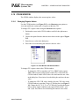
Figures in this manual show the ICS08 software’s windows and dialog boxes
as they appear in the Windows 95 environment.
1-4
M68ICS08SOM/D
P&E
1.4.2
Microcomputer
Systems, Inc.
CHAPTER 1 – INTRODUCTION
Document Conventions
This manual uses the following conventions to enhance readability:
•
Filenames, program names, code, and commands are indicated in
regular Courier New font:
SETUP.EXE
MYPDA.ASM
$INCLUDE “INIT.ASM”
•
Parameters and strings are indicated in italic Courier:
%FILE%
•
Buttons, icons, functions, and keyboard keys are indicated in small
caps:
Press the ENTER key.
Type CTRL + N or click the NEW toolbar button.
Double-click on the PROGRAM GROUP icon for your particular ICS08
software.
The RESET function of the ICS package is both an input and an output.
•
Menu names, options, and tabs are indicated in bold:
Do this by checking the Main File option in the Environment Settings
dialog’s General Options tab.
•
Dialog, edit, text, and lists boxes are indicated in initial cap italics:
Open the Open File dialog.
Select the filename in the File Name list.
Use the filename in the Main filename edit box.
•
Statement, confirmation, data entry, and field text are indicated in
Courier:
This option displays an Exit Application confirmation message.
This new filename replaces the [NONAME#] in the title bar.
1.5
SOFTWARE QUICK START INSTRUCTIONS
For users experienced in installing Motorola or other development tools, the
following steps provide a quick start installation procedure for the ICS
Package hardware and software.
For more complete instructions, refer to the M68ICS08 IN-CIRCUIT
SIMULATOR HARDWARE OPERATOR’S MANUAL for your specific
M68ICS08SOM/D
1-5
CHAPTER 1 – INTRODUCTION
P&E
Microcomputer
Systems, Inc.
part.
1. Install the ICS08 software package.
To start the software installation, run the SETUP.EXE program on
diskette 1. During installation, follow the instructions in the installation
wizard.
2. Connect the board as described in the M68ICS08 IN-CIRCUIT SIMULATOR HARDWARE OPERATOR’S MANUAL for your specific
part.
3. Start the WinIDE editor.
Start the editor either from the Windows Start menu or by doubleclicking its icon.
WinIDE is an editing application which allows seamless integration of
several different programs into one development environment.
Function keys are provided which allow one touch code assembly (F4),
as well as switching to other applications such as the Simulator (F6),
Programmer (F7), and Debugger (F8).
WinIDE is shipped so that it will open a .PPF demo project when it
is run for the first time. If you have the ICS08RKZ, for example, this
file will be called HC08RK2.PPF.
A project in WinIDE keeps track of what editing files are open, as well
as settings that indicate which external programs are currently
configured to run from WinIDE. Upon running WinIDE, two files will
be open for editing:
–
WELCOME.ASM – This file contains an overview of the ICS08
package, and briefly describes the different software components
installed in the package. It is strongly recommended that you read
this file before continuing.
–
DEMO[xxx].ASM – This is a sample application for your particular part that can be compiled and run, and provides a framework for
you to create your own application. In the ICS08JLZ package, for
example, this file would be called DEMOJL3.ASM
The following file is not open, but is used in the assembly process.
–
1-6
[xxx]REGS.INC – This is an include file which is used by the
sample application. It defines symbols for all the registers on the
particular MC68HC908 processor. In the ICS08JLW package, for
example, this file would be called JL3REGS.INC.
M68ICS08SOM/D
P&E
Microcomputer
Systems, Inc.
–
CHAPTER 1 – INTRODUCTION
For more information, see the “Getting Started” section in the
Manual Addendum for your specific processor.
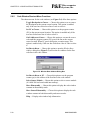
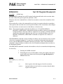
4. Assemble the code
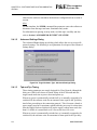
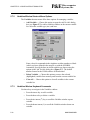
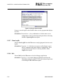
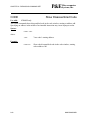
Press the ASSEMBLE/COMPILE FILE button (see Figure 1-1) on the WinIDE
Toolbar to assemble the source code in the active WinIDE window.
Additional information about the CASM08Z assembler can be found in
CHAPTER 4 – CASM08Z ASSEMBLER INTERFACE.
Figure 1-1. WinIDE Assemble/Compile File Toolbar Button
Alternative: Press the F4 function key.
5. Run the ICS08Z simulator.
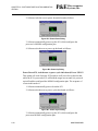
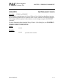
With a project or source file open in the WinIDE main window, click
the IN-CIRCUIT SIMULATOR button (see Figure 1-2) on the WinIDE
Toolbar to start the ICS08 debugger. This will debug the contents of the
active source window after they have been assembled
If communications are not established with the ICS board, it may be
necessary to select the proper port (COM1...COM8) and baud rate
(4800...28800). When communications are established, the board’s
SOCKET POWER LED will light.
For more information about debugging with ICS08Z, refer to
CHAPTER 5 – ICS08Z IN-CIRCUIT SIMULATOR.
Figure 1-2. WinIDE In-Circuit Simulator Toolbar Button
Alternative: Press the F6 function key.
6. Run the PROG08SZ programmer.
Press the PROGRAM button (see Figure 1-3) on the WinIDE Toolbar to
start the programmer. Additional information about PROG08SZ can be
found in CHAPTER 6 – PROG08SZ FLASH PROGRAMMER.
Figure 1-3. WinIDE Program Toolbar Button
M68ICS08SOM/D
1-7
CHAPTER 1 – INTRODUCTION
P&E
Microcomputer
Systems, Inc.
Alternative: Press the F7 function key.
7. Run the ICD08SZ real-time debugger.
Press the IN-CIRCUIT DEBUGGER button (see Figure 1-4) on the WinIDE
Toolbar to start the ICD08SZ in-circuit debugger and emulator.
Additional information can be found in CHAPTER 8 – ICD08SZ INCIRCUIT DEBUGGER.
Figure 1-4. WinIDE In-Circuit Debugger Toolbar Button
Alternative: Press the F9 function key.
For a step-by-step guide to getting started, refer to the “Example Project” topic
in the Manual Addendum for your specific ICS08 Kit
1.6
MC68HC908 SECURITY FEATURE
Monitor mode is a special mode on the 68HC08 device which allows an
external host to control the 68HC08 microcontroller via an asynchronous serial
interface. This feature allows a host computer to query and modify the state of
the processor including to load, debug, and program code. Without any
protection mechanism, this same feature could be used to read out the internals
of the microcontroller’s ROM.
The M68HC08 microcontrollers have an additional built-in mechanism to
protect a programmed device from being read and disassembled. The
mechanism allows a user who knows the security unlock code to enter monitor
mode and access the internal ROM/Flash. This is often desirable to allow realtime debugging of a programmed device. The ICD08SZ allows just such
functionality.
The security mechanism also allows a user who does not know the security
code to enter monitor mode, but it does not give them access to the ROM.
Upon failing the security protocol, the ROM/Flash is removed from the
memory map until the next POWER-ON reset, in which case the host has to
bypass security again. The advantage of this is that even though any on-chip
flash is not READ accessible, it is erasable. Forgotten what you programmed
into your device? The answer is simple: erase it.
A device is automatically protected in this manner. The 8 bytes from address
$FFF6 to $FFFD constitute the security unlock code which can be used to pass
the security check and get access to the Rom/Flash. Hence, if a user knows
what has been programmed into a device, they implicitly know the security
1-8
M68ICS08SOM/D
P&E
Microcomputer
Systems, Inc.
CHAPTER 1 – INTRODUCTION
unlock code.
In order to facilitate the security check on a 68HC08 device, the PROG08SZ
software continually records any changes to these security bytes and stores
them in the file SECURITY.INI. The information in this file is also shared
with P&E’s In-Circuit Debugger and In-Circuit Simulator Software. This
allows the user to reset the device and still have access to the monitor mode.
Sometimes the software cannot pass security mode. The Target Connection
and Security Dialog has a “STATUS” section which describes the different
failures and what to check in each case.
The most common reasons for not passing security are:
- You are not choosing the proper security code to pass security.
- On a power on reset, the device is not powering down to below 0.1
volts. With a class I board (ICS with processor), you may be driving
the pins on the emulation header while the device is being powered
down. This back-drives current through the ports and doesn’t let the
device fully power down. On other classes of boards, when prompted
to power down the device, the supply voltage might not be dropping
lower than 0.1v which it must to have a power-on reset.
- Make sure the “Target hardware type” is set to the proper class of
hardware.
There are several ways you can specify the proper security bytes:
- If you know the programmed security bytes, i.e. the bytes from
$FFF6-$FFFD, you can enter them in the edit box listed “User:” and
click OK(Retry).
- You can use the “Load from S19” to specify the s-record file which
contains the object information currently programmed into the MCU.
P&E’s software will automatically extract the security information
from this file and use it to pass security. Once you have specified the
s-record file, click the OK(Retry) button.
- You can erase the device. Run the PROG08SZ application, and when
the above box appears, select the “IGNORE security failure…”
option and click OK. Use the Choose Module command to select the
appropriate programming algorithm, and select Erase Module. This
should erase the device. You will have to execute the Choose Module
command again before you can access the blank device.
Note: on some older revisions of silicon, you cannot ignore the
security failure, and it will bring this box back up every time you
click OK(Retry). If this is the case, you should obtain the latest
silicon revision from Motorola.
M68ICS08SOM/D
1-9
CHAPTER 1 – INTRODUCTION
P&E
Microcomputer
Systems, Inc.
For more information on passing security and establishing communications,
please read Section 2.4 TARGET CONNECTION AND SECURITY
DIALOG carefully.
1.7
CUSTOMER SUPPORT
To obtain information about technical support or ordering parts, call the
Motorola help desk at 800-521-6274.
1-10
M68ICS08SOM/D
P&E
Microcomputer
Systems, Inc.
CHAPTER 2
SOFTWARE INSTALLATION AND INITIALIZATION
2.1
OVERVIEW
This chapter summarizes and explains how to install and initialize the ICS08
software package that is used with the Motorola ICS08 board. See the
M68ICS08 IN-CIRCUIT SIMULATOR HARDWARE OPERATOR’S
MANUAL for your specific part for information about the your ICS08 board.
2.2
THE ICS08 SOFTWARE COMPONENTS
The following is a a sample list of product components for the M68ICS08RK
package.
If your package is for a different MCU part, substitute the name of your
part for “RK.”
—
•
WINIDE.EXE
•
CASM08Z.EXE —
•
ICS08RKZ.EXE —
•
ICD08SZ.EXE
•
PROG08SZ.EXE —
—
Windows integrated development environment
editor
68HC08 cross assembler
In-circuit simulator software, optimized for the
HC08 Family of Motorola microcontrollers
Limited real-time debugger and emulator
FLASH memory programmer
Note: In this documentation, the part number ICS08Z will be understood to refer to
the In-Circuit Simulator component of the software package, while ICS08 will
refer to the entire software package.
2.2.1
WinIDE Editor
The WinIDE editor is a text-editing application that lets you use several
different programs from within a single development environment. Use the
WinIDE editor to:
M68ICS08SOM/D
2-1
CHAPTER 2 – SOFTWARE INSTALLATION AND INITIALIZATION
•
•
•
P&E
Microcomputer
Systems, Inc.
Edit source code
Launch a variety of compatible assemblers, compilers, debuggers, or
programmers
Configure the environment to read and display errors from such
programs
If you select error detection options in the Environment Settings dialog box, the
WinIDE editor will highlight errors in the source code, and display the error
messages from the compiler or assembler in the editor.
2.2.2
CASM08Z Assembler
CASM08Z is a cross assembler that creates Motorola S19 object files and
MAP files from assembly files containing 68HC08 instructions.
To debug source code in the simulator or debugger code window, load
compatible source-level map files. CASM08Z produces such map files as an
output by default.
The CASM08Z assembler supports all 68HC08 instructions and addressing
modes. It can produce .S19 object files, .MAP files, and .LST absolute listing
files. The listing files can be configured to show cycle counts.
The assembler also supports macros and conditional assembly. CHAPTER 4 –
CASM08Z ASSEMBLER INTERFACE provides additional information
about the assembler options and how to use them.
2.2.3
ICS08Z In-Circuit Simulator Software
The ICS08Z software simulates all instructions, interrupts, and peripherals for
a particular M68HC908 MCU. This simulator software can get inputs and
outputs (I/O) for the device when the external ICS08 board is attached to the
host computer. I/O from a target board can be used when the user attaches the
board to the target with the extension cable that comes with the toolkit.
Some peripherals, such as the SCI and SPI, transmit characters based on the
exact frequency of the ICS board, whereas the timer pins are controlled cycle
by cycle as the PC application simulates cycles.
The simulator can also work in stand-alone mode, without the board attached
to the host computer. In this case, simulator inputs can be specified using the
INPUTx commands.
You can start or move to the ICS08Z in-circuit simulator software from the
WinIDE editor. The ICS08Z software also can be started using standard
Windows techniques and run independently of the WinIDE editor.
The ICS08Z simulator software accepts standard Motorola .S19 object code
2-2
M68ICS08SOM/D
P&E
Microcomputer
Systems, Inc.
CHAPTER 2 – SOFTWARE INSTALLATION AND INITIALIZATION
files as input for object code simulation and debugging. If you are using a
third-party assembly- or C-language compiler, the compiler must be capable of
producing source-level map files to allow source-level debugging.
2.2.4
ICD08SZ In-Circuit Debugger
ICD08SZ allows limited real-time debugging of MC68HC908 MCUs. Unlike
the simulator, the ICD allows reading, writing, and controlling execution of the
actual processor. Code can be loaded into RAM, and code in RAM or FLASH
can be executed in real time or in single steps. For debugging in RAM,
multiple software breakpoints are available. For debugging in FLASH
memory, one hardware breakpoint is available if it is supported by your
specific MCU. For more details, see the Manual Addendum for your specific
M68HC908 device.
2.2.5
PROG08SZ FLASH Programmer
PROG08SZ allows erasing, programming, and verification of the MCU’s
FLASH memory. Individual bytes may be programmed or a .S19 object file
may be used as the source.
2.3
INSTALLING THE ICS08 SOFTWARE PACKAGE
The ICS08 software package is supplied on three 3.5-inch diskettes. Diskette 1
contains a setup program that automatically installs the software into the host
PC’s hard drive.
2.3.1
Installation Steps
To install the software on the host computer’s hard drive, follow these steps:
1. Insert floppy disk 1 or CD into the appropriate drive:
2. From the Start Menu, select the Run option.
3. In the Run dialog box, enter Setup (or click the BROWSE button to select
a different drive and/or directory) and press OK.
4. In the ICS08 Setup Wizard, follow the instructions that appear on the
screen.
M68ICS08SOM/D
2-3
CHAPTER 2 – SOFTWARE INSTALLATION AND INITIALIZATION
P&E
Microcomputer
Systems, Inc.
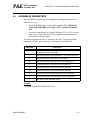
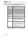
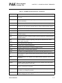
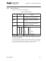
Table 2-1 lists the files and directories required to control the ICS08RK
program modules.
If your package is for a different M68HC908 MCU part, substitute the
name of your part for “RK” where it appears below:
Table 2-1. ICS08RK Software Files
Filename
2.3.2
Description
casm08z.exe
casm08z.hlp
Windows cross assembler for the 68HC08
Help for CASM08Z
icd08sz.exe
icd08sz.hlp
Windows in-circuit debugger
Help for ICD08SZ
ics08rkz.exe
ics08rkz.hlp
Windows in-circuit simulator (ICS08Z)
Help for ICS08RKZ
prog08sz.exe
prog08sz.hlp
Windows FLASH programmer
Help for PROG08SZ
winide.exe
winide.hlp
Windows integrated development
environment (WinIDE)
Help for WinIDE
rkzstart.pdf
Getting Started document for 68HC908RK2
Starting the ICS08 Software
From the Windows 95, 98, or NT Start Menu, select the WINIDE and/or ICS08
icon(s).
The other ICS08 software components may be started alone or from within the
WinIDE editor. If CASM08Z is started alone, a list of command line options
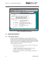
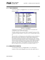
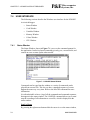
appears. On the first attempt to connect to the ICS08 board after installing the
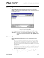
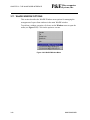
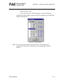
ICS08Z in-circuit simulator software, you are prompted to select the chip from
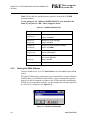
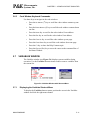
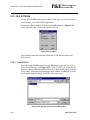
the Pick Device dialog box (see Figure 2-1):
Figure 2-1. Pick Device Dialog Box
2-4
M68ICS08SOM/D
P&E
2.4
Microcomputer
Systems, Inc.
CHAPTER 2 – SOFTWARE INSTALLATION AND INITIALIZATION
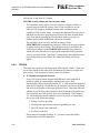
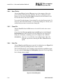
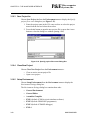
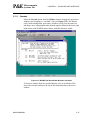
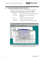
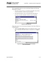
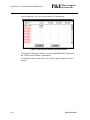
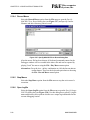
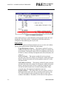
TARGET CONNECTION AND SECURITY DIALOG
The following is an explanation of each part of the target connection dialog.
For information on passing security mode, read this topic carefully, and refer
to Section 1.6 MC68HC908 SECURITY FEATURE.
Figure B-2. Target Connection And Security Dialog Box
2.4.1
TARGET HARDWARE TYPE
This section of the dialog allows you to select the type of hardware
configuration to which you are trying to connect, as well as modify specific
protocol settings.
2.4.1.1
Class Of Target Board
There are several different configurations of target boards, and P&E’s
MON08-based applications communicate to each type of hardware a little
differently. Almost all configurations are Class I or Class II. The options are:
Class I
ICS Board with processor installed. This is the standard and most common
configuration of the ICS08 boards. In this configuration, the processor is
resident in one of the sockets on the ICS board itself. The processor can be
debugged and programmed in this configuration, and an emulation cable
containing all the processor I/O signals can be connected to the user’s
M68ICS08SOM/D
2-5
CHAPTER 2 – SOFTWARE INSTALLATION AND INITIALIZATION
P&E
Microcomputer
Systems, Inc.
target board. In this configuration, the ICS board hardware can
automatically power up and down the processor in order to pass security in
the simplest fashion. The user has to be sure not to provide power from the
target, up through the emulation cable, to the processor pins themselves,
when this dialog appears. This is so that the software, when attempting to
establish communications, can fully power the processor down. The
software running on the PC controls power to the target via the serial port
DTR line. This configuration can be specified at startup in the software by
using the ICS08 command-line parameter; otherwise the software will
remember the hardware configuration from session to session.
Class II
ICS Board without processor, connected to target via MON08 Cable.
In this configuration, there is no processor resident in any of the sockets
of the ICS board itself. The processor is mounted down in the target
system. The connection from the ICS board to the target is
accomplished via the 16-pin MON08 connector. In this configuration,
since the ICS does not control power to the processor, the user will be
prompted to turn the processor’s power supply on and off. Turning off
the power supply is necessary in order to be able to pass the initial
security mode check and access the flash on the processor. A simple
reset is not enough; to pass the security check, you must first force the
processor to encounter a POR (power-on reset) which requires that the
processor’s voltage dip below 0.1v. Once security has been passed,
resetting the device or re-entering the software should be easier. This
configuration can be specified at startup in the software by using the
MON08 command-line parameter; otherwise the software will
remember the hardware configuration from session to session.
Class III
Custom Board (no ICS) with MON08 serial port circuitry built in. In
this configuration, the ICS board is not used at all. The user must
provide a serial port connection from the PC, and provide all hardware
configuration necessary to force the processor into MON08 mode upon
reset. This includes resets both internal and external to the processor. In
this configuration, because the software does not directly control power
to the processor, the user will be prompted to turn the processor’s
power supply on and off . The use will also be prompted to turn power
on and off to reset the target processor, as the PC doesn’t have control
of the target reset. Turning off the power supply is necessary mainly to
be able to pass the initial security mode check and access the flash on
the processor. A simple reset is not enough; to pass the security check,
you must first force the processor to encounter a POR (power-on reset)
which requires that the processor’s voltage dip below 0.1v. Once
2-6
M68ICS08SOM/D
P&E
Microcomputer
Systems, Inc.
CHAPTER 2 – SOFTWARE INSTALLATION AND INITIALIZATION
security has been passed, resetting the device or re-entering the
software should be easier. This configuration can be specified at startup
in the software by using the NODTR command-line parameter;
otherwise the software will remember the hardware configuration from
session to session. The Class III selection also applies to use of the ICS
board with the two-pin blank part programming connector.
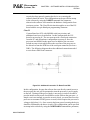
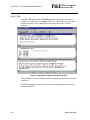
Class IV
Custom Board (no ICS) with MON08 serial port circuitry and
additional auto-reset circuit built in. In this configuration, the ICS
board is not used at all. The user must provide a serial port connection
from the PC and all hardware configuration necessary to force the
processor into MON08 mode upon reset. In addition, the user must
include an extra circuit which allows the reset line of the processor to
be driven low from the DTR line of the serial port connector (Pin 4 on a
DB9). The following diagram shows the additional connection needed
to reset from a DB9 serial connector.
Figure B-3. Additional Connection To Reset From DB9
In this configuration, because the software does not directly control power to
the processor, the user will be prompted to turn the processor’s power supply
on and off. Turning off the power supply is necessary in order to be able to
pass the initial security mode check and access the flash on the processor. A
simple reset is not enough; to pass the security check, you must first force the
processor to encounter a POR (power-on reset) which requires the processor’s
voltage to dip below 0.1v. Once security has been passed, resetting the device
should be facilitated by the above circuitry. This configuration can be specified
at startup in the software by using the NODTRADD command-line parameter;
M68ICS08SOM/D
2-7
CHAPTER 2 – SOFTWARE INSTALLATION AND INITIALIZATION
P&E
Microcomputer
Systems, Inc.
otherwise the software remembers the hardware configuration from session to
session.
Also:
For the simulator, the /SIM08 command-line parameter causes the software to
disconnect from the target and enter Simulation Only mode.
For information on passing security mode, read this topic carefully and also
refer to Section 1.6 MC68HC908 SECURITY FEATURE.
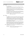
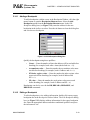
2.4.1.2
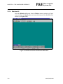
Advanced Settings Dialog
The Advanced Button brings up a dialog which allows the user to set specific
protocol settings. The following is an explanation of each part of the advanced
settings dialog.
Figure B-4. Target Hardware Type: Advanced Settings Dialog
2.4.1.3
Tpd and Tpu Timing
These timing parameters are mostly designed for Class I boards, although the
delays are valid for all classes of boards. Many of the ICS boards and user
target boards need time to power down and power up.
Whenever power is automatically switched off, or is manually requested to be
switched off, the software waits for an amount of time equal to the Tpd delay
time before proceeding to the connection protocol. This is because a board or
power supply may have capacitance which holds the power up for a short time
after the supply has been switched off, but the supply voltage must reach less
than 0.1v before it is turned back on if a Power-On reset is to occur.
Whenever power is automatically switched on, or is manually requested to be
switched on, the software waits for an amount of time equal to the Tpu delay
2-8
M68ICS08SOM/D
P&E
Microcomputer
Systems, Inc.
CHAPTER 2 – SOFTWARE INSTALLATION AND INITIALIZATION
time before attempting to contact the 68HC08 processor. This is to allow time
not only for power to be fully available, but to wait until any reset driver has
finally released the RESET line. On many ICS08 boards (such as the
ICS08RK, M68ICS08JL3, M68ICS08JLJK, and ICS08GP20) the Tpu can be
decreased to as little as 250ms with no adverse affects .
Target has RESET button (class III boards only): The software
occasionally needs to get control of the target. On systems which are Class III
boards with the monitor mode circuitry built-in (including RS-232 driver),
there is no means to reset the target to gain control. If the board has a reset
button, the software can use this to gain control of the target system. If this
option is checked, the software will prompt the user to push the target reset
button when a reset of the target system is desired. If the option is unchecked,
the software will ask the user to power cycle the target system to achieve a
reset.
2.4.1.4
MON08 Cable connection communications type (Class II boards
Only)
This selection box is valid only for Class II hardware configurations using the
MON08 cable. It allows the user to specify the sequence that the software uses
to power up the ICS system. When the software tries to create a power-on
reset condition, two events must occur:
1. Power of the target MCU must go below 0.1v. This means that the
processor can not be receiving power from its power pins, nor can it have a
significant voltage being driven on port pins or the IRQ line, as these will
drive the MCU power back through these pins. It is crucial, therefore, to
have the ICS and the Target both powered down at some point in time.
2. The processor MON08 configuration pins, including IRQ, must be
properly driven when the target processor resets to drive it into monitor
mode. If these pins are not set up properly before the processor powers up,
the processor may start up in user mode.
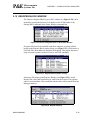
Power Down ICS, Ask the user to power down their board, Power Up ICS,
Ask the user to power up their board
This is the default option and should work for most, if not all, ICS08/Target
Board solutions. Refer to the manual addendum under startup for the settings
for a specific ICS board. It requires the user go through two dialog stages, and
requires more time than simply cycling the power.
1. Software automatically powers down the ICS.
M68ICS08SOM/D
2-9
CHAPTER 2 – SOFTWARE INSTALLATION AND INITIALIZATION
P&E
Microcomputer
Systems, Inc.
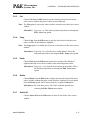
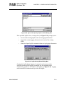
2. Software Asks the user to power down the board as follows:
Figure B-5. Power Down Dialog
3. Software automatically powers up the ICS, which configures the
processor’s MON08 configuration pins.
4. Software asks the user to power up the board as follows:
Figure B-6. Power Up Dialog
Power Down ICS, Ask the user to power cycle their board, Power UP ICS
This option will work for many ICS boards as well, but relies on the fact that
while the ICS is powered off, it will hold the target in reset until it is powered
up itself and has configured the MON08 configuration pins. The sequence of
events in this mode is:
1. Software automatically powers down the ICS.
2. Software asks the user to power cycle their board as follows:
Figure B-7. Power Cycle Dialog
3. Software automatically powers up the ICS, which configures the
processors MON08 configuration pins.
2-10
M68ICS08SOM/D
P&E
2.4.2
Microcomputer
Systems, Inc.
CHAPTER 2 – SOFTWARE INSTALLATION AND INITIALIZATION
PC SERIAL PORT CONFIGURATION
This allows configuration of the COM port and baud rate that the PC uses to
attempt communication to the target. The baud rate depends on the processor’s
port pin values during reset, and the frequency of the oscillator connected to
the processor. Refer to your microcontroller part specification for information
on baud rates for particular processor frequencies.
A sample list of ICS boards with targets of different frequencies is listed here:
M68ICS08JL3
M68ICS08JL3
4.9152MHZ
9.8304MHZ
9600 Baud
19200 Baud
M68ICS08JLJK
M68ICS08JLJK
4.9152MHZ
9.8304MHZ
4800 Baud
9600 Baud
ICS08GP20
ICS08GP20
4.9152MHZ
9.8304MHZ
9600 Baud
19200 Baud
If the “Port” and “Baud” setting are grayed out and cannot be changed, this is
because the COM port is currently open by the software. Click the “Close
COM Port” button and you will then be able to change these values.
Note that if you are using a Class II or III board and you are connecting to a
target without an oscillator or crystal (i.e., the processor has an internal
oscillator such as the 68HRC08JL3), you will have to provide an external
clock source to the processor because, in monitor mode, an internal oscillator
is automatically bypassed.
For information on passing security mode, read this topic carefully and also
refer to Section 1.6 MC68HC908 SECURITY FEATURE.
2.4.3
TARGET MCU SECURITY BYTES
One of the steps that is necessary to properly bypass security is to provide the
proper security code for the information that is programmed into the part. This
holds true even when the part is blank.
The security code consists of the 8 values which are currently stored in flash
locations $FFF6 - $FFFD of the processor. The PROG08SZ flash
programming software continually records any changes to these security bytes
and stores them in the file SECURITY.INI. The information in this file is
shared with P&E's In-Circuit Debugger and In-Circuit Simulator software, and
will appear in the dialog box. This allows the user to specify which security
code to use to pass security.
This dialog can also be used by the user to manually enter the proper security
bytes via the USER setting, or to load the security bytes from the same .S19
file which was programmed. The bytes are loaded from an .S19 file by
M68ICS08SOM/D
2-11
CHAPTER 2 – SOFTWARE INSTALLATION AND INITIALIZATION
P&E
Microcomputer
Systems, Inc.
clicking the “Load from S19” button.
IGNORE security failure and enter monitor mode
This checkbox can be used to cause the software to ignore a failure to
properly pass the 68HC08 security check. If the checkbox is set, the
software will attempt to establish monitor mode communications
regardless of the security status. As long as the Baud and Port are correct,
and the device has been properly powered, this will allow monitor mode
entry. Note that by ignoring the security check failure, you may use
monitor mode, but the ROM/Flash will not be accessible.
The checkbox can be set to be checked on startup via the
FORCEBYPASS command-line parameter, which will cause the software
to ignore security check failure. This checkbox can be overridden to be
unchecked on startup via the FORCEPASS command-line parameter,
which will cause the software to pop-up the connection dialog when the
security check has failed. Note that if a connection is not established for a
reason other than security failure, the connection dialog will always
appear.
2.4.4
STATUS
The status area consists of one status string following the “Status:” label, and
seven items which list the state of the last attempt to connect to a target and
pass security. The description for these items is as follows:
0 – ICS Hardware loopback detected:
Every ICS or board which supports MON08 has a serial loopback in
hardware which, by connecting the transmit and receive lines,
automatically echoes characters from the PC. A valid character transmitted
from the PC should be echoed once by the loopback circuitry on the board
and once by the monitor of the target processor itself. This status indicates
whether or not the first echoed character from the hardware loopback was
received when one of the security bytes was transmitted. If the status is
‘N’, which indicates that the character was not received, it is most likely
due to one of the following reasons:
1. Wrong Com Port specified.
2. The baud rate specified was incorrect (probably too low).
3. The ICS/Target is not connected.
4. No Power to the ICS.
If this status bit responded with an ‘N’, you must correct this before
analyzing the reset of the status bits.
2-12
M68ICS08SOM/D
P&E
Microcomputer
Systems, Inc.
CHAPTER 2 – SOFTWARE INSTALLATION AND INITIALIZATION
1 – Device echoed some security bytes :
The monitor resident in a 68HC08 device automatically echoes every
incoming character when it is in monitor mode. A valid character
transmitted from the PC should be echoed once by the loopback circuitry
on the board and once by the monitor of the target processor itself. This
status indicates whether or not the second echoed character from the
monitor response was received when one of the security bytes was
transmitted. If the status is ‘N’, which indicates that the character was not
received, or not received properly, it is most likely due to one of the
following reasons:
1. The baud rate specified was incorrect.
2. The part did not start the monitor mode security check on reset.
Signals to force monitor mode may be incorrect.
3. No Power to the ICS.
If this status bit responded with an ‘N’, you must correct this before
analyzing the reset of the status bits.
2 – Device echoed all security bytes:
In order to pass security, the software must send 8 security bytes to the
processor. The processor should echo each of these eight bytes twice. If
all 8 bytes did not get the proper two-byte echo, this flag will be ‘N’.
Reasons for this include:
1. The part did not start the monitor mode security check on reset.
Signals to force monitor mode may be incorrect.
2. The baud rate specified was incorrect.
3. The processor was not reset properly. Check the “Target Hardware
Type” and if you are connecting to a class II board, check the “MON08
cable communication connections type” in the “advanced settings”
dialog.
3 – Device signaled monitor mode with a break:
Once the processor has properly received the 8 bytes from the PC software
to complete its security check, it should transmit a break character to the
PC signaling entry into monitor mode. This break should be sent
regardless of whether the security check was successfully passed. If a
break was not received from the processor, this flag will be ‘N’. Reasons
for this include:
1. The baud rate specified was incorrect.
2. The processor was not reset properly. Check the “Target Hardware
M68ICS08SOM/D
2-13
CHAPTER 2 – SOFTWARE INSTALLATION AND INITIALIZATION
P&E
Microcomputer
Systems, Inc.
Type”. If you are connecting to a class II board, check the “MON08
cable communication connections type” in the “advanced settings”
dialog.
4 – Device entered monitor mode:
Once the software has received, or failed to receive, a break from the
processor, it attempts to communicate with the monitor running on the
68HC08 processor. It tries to read the monitor version number by issuing a
monitor mode read. If the processor fails to respond properly to this
command, this flag will be ‘N’.
5 – Reset was Power-On Reset:
If the device properly entered monitor mode (4), the software will read the
reset status register (RSR). This read does not affect the security sequence,
and occurs purely for diagnostic reasons. The reset status register indicates
the conditions under which the processor underwent the last reset. For the
software to pass the security check properly, it MUST first cause the
processor to undergo a Power-On Reset. The software reads the reset
status register to determine if the last reset was indeed caused by power-on.
The result of the reset status register is indicated in parentheses after the
flag value. If the highest bit is not set then the reset was not a power on
reset, and the flag will indicate ‘N’. Reasons for this include:
1. The processor did not power all the way down because power was
being supplied to the processor through either the port pins, IRQ line,
RESET line, or power pins.
2. The voltage driven on the power pin of the processor did not go
below 0.1 volts.
3. The processor was not reset properly. Check the “Target Hardware
Type”. If you are connecting to a class II board, check the “MON08
cable communication connections type” in the “advanced settings”
dialog.
6 – ROM is accessible (un-secured):
If the device properly entered monitor mode (4), the software reads
locations $FFF6-$FFFF to determine if the processor passes the security
check. Memory locations which are invalid or protected read back from the
device as $AD. If all bytes from $FFF6-$FFFF read a value of $AD, it is
assumed the device is secure, and the flag value is an ‘N’. If all flags 0-5
register a value of ‘Y’ and flag 6 register a value of ‘N,’ then the reset
process has gone correctly except that the security code used to pass
security was incorrect. Specify the correct security code and try again, or
IGNORE the security failure and erase the device. Once you erase a
secured device, you must exit the software and restart it in order to pass
2-14
M68ICS08SOM/D
P&E
Microcomputer
Systems, Inc.
CHAPTER 2 – SOFTWARE INSTALLATION AND INITIALIZATION
security.
2.4.5
ADDITIONAL DIALOG BUTTONS
The following buttons are also available:
Contact target with these settings – This causes the software to attempt to
cause a power on reset of the target, and to attempt to pass security with the
settings in this dialog.
Simulation Only – This button is only visible in In-Circuit Simulation. This
causes the In-Circuit Simulator not to use the target and, instead, to do
completely software-based simulation. The /SIM08 command-line parameter
has the same function.
Halt – This causes the software to terminate and return to the calling
environment.
M68ICS08SOM/D
2-15
CHAPTER 2 – SOFTWARE INSTALLATION AND INITIALIZATION
2-16
P&E
Microcomputer
Systems, Inc.
M68ICS08SOM/D
P&E
Microcomputer
Systems, Inc.
CHAPTER 3
THE WinIDE USER INTERFACE
3.1
OVERVIEW
This chapter is an overview of the WinIDE windows, menus, toolbars, dialog
boxes, options, and procedures for using each.
3.2
WINDOWS INTEGRATED DEVELOPMENT ENVIRONMENT
The Windows integrated development environment (the WinIDE editor) is a
graphical interface for editing, compiling, assembling, and running these
external ICS08 programs:
•
CASM08Z assembler
•
ICS08Z in-circuit simulator
•
PROG8SZ FLASH programmer
•
ICD08SZ real-time in-circuit debugger
The WinIDE user interface consists of standard Windows title and menu bars,
a WinIDE toolbar, a main window containing any open source or project file
windows, and a status bar. The WinIDE components are labeled in Figure 3-1
and described in Section 3.3.2 Main Window Components.
M68ICS08SOM/D
3-1
CHAPTER 3 – THE WinIDE USER INTERFACE
P&E
Microcomputer
Systems, Inc.
Figure 3-1. WinIDE Window Components
3.3
3.3.1
WinIDE MAIN WINDOW
Main Window Functions
When you first start the WinIDE editor, a project is loaded, and several
assembly source files are automatically opened for editing. As you open or
create source files or a project, they appear as subordinate windows in the main
window. You can move, size, and arrange subordinate windows using standard
Windows techniques and the WinIDE Window menu options.
Use the WinIDE main window to:
3-2
•
Open, create, edit, save, or print source (*.ASM, *.LST, *.MAP, and
*.S19) or project (*.PPF) files.
•
Configure the desktop and environment settings for the editor,
assembler, compiler, debugger, and other programs.
•
Launch the in-circuit simulator, compiler, debugger, programmer, or
another program.
M68ICS08SOM/D
P&E
3.3.2
Microcomputer
Systems, Inc.
CHAPTER 3 – THE WinIDE USER INTERFACE
Main Window Components
Figure 3-1 shows how the WinIDE main window might look during a typical
editing project and labels the standard window components:
•
Title bar — The title bar appears at the top edge of the main window
and contains:
–
The application title
–
The name of the currently open project file
–
Windows control buttons for closing, minimizing, or maximizing
the window
•
Menu bar — The menu bar appears immediately below the title bar
and contains the names of the WinIDE menus.
•
Toolbar — The WinIDE toolbar appears just below the menu bar and
contains shortcut buttons for frequently used menu options.
•
Main window — The main window area is the inside portion of the
main window which contains the open subordinate windows that you
can resize, reposition, minimize, or maximize using standard Windows
techniques or Window menu options.
•
Status bar — The status bar (see Figure 3-2) appears along the bottom
edge of the main window and contains a number of fields (depending
on the project) that show:
–
Source file line and column numbers of the blinking insertion point
cursor
–
System status or progress of the current window; for example,
when the window is edited, the status will be modified
–
Total number of lines in the active window
–
Top — the current line position in the file of the top of the active
window
–
Bytes — displays the total number of bytes in the active window
–
Insert/overwrite mode — indicates the current typing mode
The status fields expand and contract as client area contents change and
files become active.
Figure 3-2. WinIDE Status Bar
M68ICS08SOM/D
3-3
CHAPTER 3 – THE WinIDE USER INTERFACE
3.4
3.4.1
P&E
Microcomputer
Systems, Inc.
GETTING STARTED
Prerequisites for Starting the WinIDE Editor
Before you can start the WinIDE editor, the Windows operating environment
must be running and the ICS08 software package must be installed on the host
computer.
Remember that for the ICS08 In-Circuit Simulator to run with the ICS08
board, the asynchronous communications cable must connect the ICS08 board
to the host computer, and the power to the board must be on. See the
M68ICS08 IN-CIRCUIT SIMULATOR HARDWARE OPERATOR’S
MANUAL for your specific part for instructions on connecting the board to the
host computer. Stand-alone simulation can be done without the ICS board
using Simulation Only mode.
3.4.2
Starting the WinIDE Editor
To start the editor, select the WinIDE icon by double-clicking the PROGRAM
GROUP icon for your ICS08 software in the Windows 3.1 program manager or
by selecting the icon from the Windows 95 Start menu.
3.4.3
Opening Source Files
To open files within WinIDE, choose the Open option from the File menu (or
click the FILE button on the WinIDE toolbar). In the Open File dialog box,
choose the files that will make up your project:
1. Select the drive and the directory folder containing the files to be
opened.
2. You may use the Filename text box to specify a filename or a wildcard/
extension to filter the list of filenames (or choose a file type from the
List files of type list). The default file type is .ASM, but you can also
choose:
•
*.c
—
source code files
•
*.lst
—
listing files
•
*.txt
—
text files
•
*.*
—
all files
To add more filter types, change the environment settings with the
General Editor tab in the main menu.
When all of the project files have been selected, click the OK button to open the
files in the WinIDE main window.
3-4
M68ICS08SOM/D
P&E
3.4.4
Microcomputer
Systems, Inc.
CHAPTER 3 – THE WinIDE USER INTERFACE
Navigating in the WinIDE Editor
To navigate among the several subordinate windows in which the project files
are displayed in the WinIDE main window:
•
Choose the subordinate window’s filename from the Window menu or
click on the file’s title bar to bring it to the front of the cascaded stack.
•
If you have multiple files open in the editor, you may choose the Tile
option from the Window menu to lay out all of the sub-windows so
that all are visible, or choose the Cascade option to arrange all
windows so that only the top window is entirely visible.
•
Regardless of how you arrange the windows, the title bars of all
windows are visible.
To move between the WinIDE editor and the external ICS08 software
components, use the toolbar buttons or function keys shown in Table 3-1. To
switch back to the editor from a program, click the program’s BACK TO EDITOR
toolbar button.
Table 3-1. Navigating Between External Programs
Switch To
CASM08Z Assembler
ICS08Z Simulator
PROG08SZ Programmer
ICD08SZ Debugger
Toolbar
Button
EXE Tab
Function Key
—
F4
EXE1
F6
EXE2
F7
EXE3
F8
For a complete description of all the WinIDE toolbar buttons, see Table 3-2.
M68ICS08SOM/D
3-5
CHAPTER 3 – THE WinIDE USER INTERFACE
3.4.5
P&E
Microcomputer
Systems, Inc.
Using Markers
Markers provide a convenient way to mark multiple points in a file for
navigating between frequently visited locations while you are editing. You can
set as many as 10 markers in source files in the WinIDE editor. A marker
appears in the file as a small button labeled with the marker number.
When you save the project, the WinIDE editor saves the markers for all open
edit files as well, so that when you open the project again, the markers are still
set.
To set a marker anywhere in the file:
1. Place the cursor on the line where you want the marker to be.
2. Press CNTL + SHIFT + N, where N is a value from 0 to 9 indicating the
marker number. A marker appears at the far left of the line.
To move to a marker, press CNTL + N, where N is denotes a marker number
between 0 and 9. This feature is useful when editing a large file.
Markers can also be set, changed, navigated to, or cleared using options on the
Edit shortcut menu (see Figure 3-3). Open the Edit shortcut menu by clicking
the right mouse button in any edit window.
Figure 3-3. WinIDE Edit Shortcut Menu
To set or clear a marker using the Edit shortcut menu options, follow these
steps:
1. With the cursor in any editing window, click the right mouse button to
open the shortcut menu.
2. Position the cursor on the line where the marker should appear. Click
the right mouse button to display the shortcut menu.
3. Click the Toggle Marker 0-9 option to open the list of markers.
4. Click once on the marker to toggle. When the marker number is
checked, it is toggled on; when the marker number is unchecked, it is
toggled off.
3-6
M68ICS08SOM/D
P&E
Microcomputer
Systems, Inc.
CHAPTER 3 – THE WinIDE USER INTERFACE
To move to a marker number using the shortcut menu options:
1. With the cursor anywhere in the edit file, click the right mouse button
to open the Edit shortcut menu.
2. Click on the Go To Marker 0-9 option to open the Marker sub-menu
(see Figure 3-4), and choose the marker number to move to.
Figure 3-4. Marker Sub-menu
You can execute many WinIDE menu options using either keyboard
commands or toolbar buttons. For example, to move to a marker, press the
CTRL + SHIFT + N key combination, where N is the marker number.
M68ICS08SOM/D
3-7
CHAPTER 3 – THE WinIDE USER INTERFACE
3.5
P&E
Microcomputer
Systems, Inc.
COMMAND-LINE PARAMETERS
The WinIDE editor lets you specify command-line options to pass to each
executable program. The name of the currently edited file, or some derivative
thereof, can be passed within these options. To pass the current filename,
specify a parameter %FILE%. The WinIDE editor substitutes this string with
the current filename at execution time. You may also change the extension of
the passed filename, by specifying it within the %FILE% parameter. For
example, to specify an .S19 extension on the current filename, specify a
%FILE.S19% parameter. For example, if the current filename being edited is
MYPDA.ASM:
Parameters
Specified
Parameters Passed
(w/o quotes)
Parameters Passed
(w/ quotes)
%FILE% S L D
MYPDA.ASM S L D
“MYPDA.ASM” S L D
%FILE.S19% 1
@2
MYPDA.S19 1 @2
“MYPDA.S19” 1 @2
Although it is by default the currently edited filename that is used in the
%FILE% parameter substitution, the environment can be configured always to
pass the same filename. Do this by checking the Main File option in the
Environment Settings dialog box’s General Options tab. This technique is
useful if you want to pass a specific filename to the external program without
regard to what is being edited.
Note: All external programs have a checkbox option to allow the user to specify
whether or not to enclose the filename in double quotes. Double quotes are
necessary if your filename has spaces in it, so that the computer will interpret
multiple words as one parameter.
3.6
WinIDE TOOLBAR
The WinIDE toolbar (see Figure 3-5) provides a number of convenient
shortcut buttons that duplicate the function of the most frequently used menu
options. A tool tip or label pops up when the mouse button lingers over a
toolbar button, identifying the button’s function.
Figure 3-5. WinIDE Toolbar
Table 3-2 identifies and describes the WinIDE toolbar buttons and function
keys.
3-8
M68ICS08SOM/D
P&E
Microcomputer
Systems, Inc.
CHAPTER 3 – THE WinIDE USER INTERFACE
Table 3-2. WinIDE Toolbar Buttons
Icon
Button Label
EXTERNAL PROGRAM 1
Function Key: F6
EXTERNAL PROGRAM 2
Function Key: F7
EXTERNAL PROGRAM 3
Function Key: F8
EXTERNAL PROGRAM 4
Function Key: F9
ASSEMBLE/COMPILE FILE
Function Key: F4
Button Function
Call the External Program 1 specified in the Environment
Settings dialog box’s EXE 1 tab. Default: ICS08 Simulator
Call the External Program 2 specified in the Environment
Settings dialog box’s EXE 2 tab. Default: PROG08SZ
Call the External Program 3 specified in the Environment
Settings dialog box’s EXE 3 tab. Default: ICD08SZ
Call the External Program 4 specified in the Environment
Settings dialog box’s EXE 4 tab.
Assemble or compile the active source window, using
CASM08Z.
CUT
Cut the selected text from the active source window (this
button is a shortcut for the Edit - Cut menu option).
COPY
Copy the selected text in the active source window to the
Windows clipboard (this button is a shortcut for the Edit Copy menu option).
PASTE
Paste the contents of the Windows clipboard at the insertion
point location in the active source window (this button is a
shortcut for the Edit - Paste menu option).
OPEN FILE
Close the active source window (this button is a shortcut for
the File - Open menu option).
SAVE FILE
Save the file in the active source window (this button is a
shortcut for the File - Save menu option).
SAVE PROJECT
(ALL FILES & SETUP)
Save the active project (this button is a shortcut for the
Environment - Save Project As menu option).
CLOSE FILE
Close the active source window (this button is a shortcut for
the File - Close menu option).
VIEW REGISTER FILES
Set up peripheral registers interactively.
M68ICS08SOM/D
3-9
CHAPTER 3 – THE WinIDE USER INTERFACE
3.7
P&E
Microcomputer
Systems, Inc.
WinIDE MENUS
Table 3-3 summarizes WinIDE menu titles and options.
Table 3-3. WinIDE Menus and Options Summary
Menu
Title
File
Edit
3-10
Option
Description
New File
Open a new file window (No name).
Open File
Display the Open File dialog box to choose a file to open.
Save File
Save the current file.
Save File As
Open the Save As dialog box to choose a directory and
filename in which to save the current file.
Close File
Close the current file.
Print
Open the Print dialog box to print the current file.
Print Setup
Open the Print Setup dialog box to choose printer options.
Exit
Close the WinIDE editor.
Undo
Undo the last action.
Redo
Redo the last action.
Cut
Cut the selection to the clipboard.
Copy
Copy the selection to the clipboard.
Paste
Paste the contents of the clipboard.
Delete
Delete the selection.
Select All
Select all text in the current window.
M68ICS08SOM/D
P&E
Microcomputer
Systems, Inc.
CHAPTER 3 – THE WinIDE USER INTERFACE
Table 3-3. WinIDE Menus and Options Summary (Continued)
Menu
Title
Environment
Search
Window
Help
Option
Description
Open Project
Open the Specify Project File to Open dialog box.
Save Project
Save the current project.
Save Project As
Open the Specify Project File to Save dialog box.
Close/New Project
Close the current project file or open a new project file if no
current file.
Set Up Environment
Open the Environment Settings dialog box to change these
settings:
– General Environment
– External EXE 2
– General Editor
– External EXE 3
– Assembler/Compiler
– External EXE 4
– External EXE 1
Set Up Font
Open the Font dialog box to specify font options for the text in
the current file.
Find
Open the Find dialog box to enter a search string.
Replace
Open the Replace dialog box to enter a search and
replacement string.
Find Next
Go to the next occurrence of the search string.
Go to Line
Open the Go to Line Number dialog box and enter a line
number to go to in the current file.
Cascade
Cascade open windows with active window on top.
Tile
Tile open windows with active window on top.
Arrange Icons
Arrange minimized window icons along the bottom edge of the
main window.
Minimize All
Minimize all open windows.
Split
Toggle a split window in the active file.
Windows (by name)
Itemize the open and minimized windows by name in order of
opening.
Contents
Opens the WinIDE Help Contents Page of the help file.
About
Displays the WinIDE About Window.
M68ICS08SOM/D
3-11
CHAPTER 3 – THE WinIDE USER INTERFACE
3.8
P&E
Microcomputer
Systems, Inc.
WinIDE FILE OPTIONS
This section describes the WinIDE File menu options for managing and
printing source files or exiting the WinIDE editor.
To select a File option, click once on the File menu title to open the File menu
(see Figure 3-6). Click on an option to perform the operation. Use accelerator
or shortcut keystrokes to execute the option.
Figure 3-6. WinIDE File Menu
3.8.1
New File
Choose New File from the File menu to open a new client window in the
WinIDE main window. The title of the new window in the title bar defaults to
[NONAME#], where # reflects the number of new source windows created
during this session. If there is an active project, the project name appears in the
title bar. If there is no project, [No Project] precedes the window name.
Use this new window to enter source code. When you save the contents of this
window, the WinIDE editor prompts you for a new filename. This new
filename replaces the [NONAME#] in the title bar.
Alternatives: Type CTRL + N or click the NEW toolbar button. This is the
keyboard equivalent to choosing the File - New File menu
option.
3-12
M68ICS08SOM/D
P&E
3.8.2
Microcomputer
Systems, Inc.
CHAPTER 3 – THE WinIDE USER INTERFACE
Open File
Choose Open File from the File menu to open the Open File dialog box
(Figure 3-7) and choose an existing filename, file type, directory, and network
(if applicable) to open.
Figure 3-7. Open File Dialog Box
Each file opens in its own client window within the main WinIDE window.
Alternatives: Type CTRL + O or click the OPEN button on the toolbar. This is
the keyboard equivalent to choosing the File - Open File menu
option.
3.8.3
Save File
Choose Save File from the File menu to save the file in the active source
window.
•
If you are saving the file for the first time (that is, it has not yet been
named), the Save As dialog box appears. Enter a new filename for the
file and accept the current file type, directory or folder, and drive, or
choose new options. Press the OK button to save the file to the selected
drive/directory.
•
If the file has been saved previously (and has a name), the file is saved
with the filename, in the directory and drive previously specified, and
the source window remains open.
Alternatives: Type CTRL + S or click the SAVE button on the toolbar. This is the
keyboard equivalent to choosing the File - Save File menu
option.
M68ICS08SOM/D
3-13
CHAPTER 3 – THE WinIDE USER INTERFACE
3.8.4
P&E
Microcomputer
Systems, Inc.
Save File As
Choose Save File As from the File menu to save the contents of the active
source window and assign a new filename. The Save As dialog box opens.
Enter a new file name in the File Name field and click the OK button to save
the file and return to the source window.
To save the file with the name of an existing file, select the filename in the File
Name list, and click the OK button. A Confirmation dialog box will ask you to
confirm that you want to overwrite the existing file.
3.8.5
Close File
Choose Close File from the File menu to close the file in the active source
window.
If you chose the Give user option to save each file option in the General
Environment tab in the Environment Settings dialog box, the Information
dialog box will display, reminding you to save changes to the .ASM file.
Alternatives: Type CTRL + D or click the CLOSE toolbar button. This is the
keyboard equivalent to choosing the File - Close File menu
option.
3.8.6
Print File
Choose Print from the File menu to open the Print dialog box (see Figure 3-8)
and choose options for printing the active source window.
The Print dialog box for your operating system and printer capabilities opens
for you to choose Print range and Print quality. Open the Print Setup dialog
box to change printer settings.
Figure 3-8. Print Dialog Box
3-14
M68ICS08SOM/D
P&E
Microcomputer
Systems, Inc.
CHAPTER 3 – THE WinIDE USER INTERFACE
Note: The Print option is active when at least one source window is open. The
WinIDE editor disables the option if no window is open.
3.8.7
Print Setup
Choose the Print Setup option from the File menu to open the Print Setup
dialog box for your operating system and printer. Use this dialog box to choose
the printer, page orientation, paper size, and other options for your printer.
3.8.8
Exit
Choose the Exit option from the File menu to close the editor. If a project or
source window is open, the editor closes the files and exits.
Alternatives: Type ALT + F4. This is the keyboard equivalent to choosing the
File - Exit menu option.
3.9
WinIDE EDIT OPTIONS
This section describes the WinIDE Edit menu options for creating or editing
source file contents. To perform an edit operation, click once on the Edit menu
title to open the Edit menu (see Figure 3-9). Click on an option to perform the
operation.
Figure 3-9. WinIDE Edit Menu
M68ICS08SOM/D
3-15
CHAPTER 3 – THE WinIDE USER INTERFACE
3.9.1
P&E
Microcomputer
Systems, Inc.
Undo
Choose Undo to undo or reverse the last action or change you made in the
active source window.
Changes that you make to the contents of the window (and that are undoable or
reversible) are saved in an undo stack, where they accumulate, up to a
maximum of 20 instances. You can reverse your changes in descending order
of the sequence in which they were made. If no more changes remain in the
stack, the Undo option is disabled.
Reversible actions are local to each source window. Commands that are not
reversible do not contribute to the undo stack. You cannot, for example, undo
the command to open a new window using the Undo command.
Alternatives: Type CTRL + Z. This is the keyboard equivalent to selecting the
Edit - Undo menu option.
3.9.2
Redo
Choose Redo to restore the most recently undone action in the active window.
The Redo option restores actions undone or reversed by the Undo option, in
ascending order, that is, last action first. Reversible changes to the window’s
contents accumulate in the window’s undo stack. Once a change has been
reversed using the Undo option, the change can be reversed, using the Redo
option. When no more changes remain (that is, the top of the Redo stack is
reached) the Redo option is disabled.
Some commands are not reversible. They do not contribute to the undo stack
and therefore cannot be redone. For example, because reversible actions are
local to each source window, opening a new window is an action that cannot be
undone using the Undo command, or redone using the Redo command.
Note: The Redo option is active only if you have used the Undo option to modify the
contents of the active source window.
Alternative: Type SHIFT + CTRL + Z. This is the keyboard equivalent to
selecting the Edit - Redo menu option.
3-16
M68ICS08SOM/D
P&E
3.9.3
Microcomputer
Systems, Inc.
CHAPTER 3 – THE WinIDE USER INTERFACE
Cut
Choose Cut from the Edit menu to cut the currently selected text from the
active source window and place it on the system clipboard.
Note: The Cut option is active only when you have selected text in the active source
window.
Alternative: Type CTRL + X. This is the keyboard equivalent to selecting the
Edit - Cut menu option.
3.9.4
Copy
Choose Copy from the Edit menu to copy the selected text from the active
source window to the Windows clipboard.
Note: The Copy option is available only if you have selected text in the active source
window.
Alternatives: Type CTRL +C or click the COPY toolbar button. This is the
keyboard equivalent to selecting the Edit - Copy menu option.
3.9.5
Paste
Choose Paste from the Edit menu to paste the contents of the Window’s
clipboard into the active source window at the insertion point location.
Alternatives: Type CTRL + V or click the PASTE button on the toolbar. This is
the keyboard equivalent to selecting the Edit - Paste menu
option.
3.9.6
Delete
Choose Delete from the Edit menu to delete the selected text from the active
source window without placing it on the Windows clipboard. Text you delete
using the Delete option can be restored only by using the Undo option.
Alternatives: Press the DELETE key. This is the keyboard equivalent to
selecting the Edit - Delete menu option.
3.9.7
Select All
Choose Select All from the Edit menu to select all text in the active source
window.
M68ICS08SOM/D
3-17
CHAPTER 3 – THE WinIDE USER INTERFACE
P&E
Microcomputer
Systems, Inc.
3.10 WinIDE ENVIRONMENT OPTIONS
This section describes the WinIDE Environment menu options for managing
project information and setting up environment and font settings for a project.
Environment settings represent the current environment and configuration
information for the WinIDE editor. These settings are stored in the
WINIDE.INI file, from which they are loaded each time you start the editor,
and saved each time you exit from the editor.
When you start the editor, the application opens the WINIDE.INI file and
reads the project information. If there is an open project, the project file’s
environment settings are read and used instead. This permits different
environment configurations for different projects.
Environment information stored in the WINIDE.INI file includes:
•
If a project is open, its name
•
Current font information
•
Current source directory and project directory paths
•
The preferences and options you set in the Environment Settings dialog
box tabs, including:
–
General Environment options
–
General Editor options
–
Executable options for assembler, debugger, compiler, and programmer
To choose an environment option, click once on the Environment menu title
(see Figure 3-10) to open the menu. Click on the option to execute.
Figure 3-10. WinIDE Environment Menu
Project files have the extension .PPF; they store two kinds of information:
3-18
•
Environment settings — User settings and WinIDE configuration
parameters
•
Desktop information open edit windows, size and location, markers
M68ICS08SOM/D
P&E
3.10.1
Microcomputer
Systems, Inc.
CHAPTER 3 – THE WinIDE USER INTERFACE
Open Project
Choose Open Project from the Environment menu to choose the project file
in the Specify project file to open dialog box (Figure 3-11).
1. Enter the project name in the File name text box or select the project
name from the list box below the text box.
2. Press the OK button to open the new project file (or press the CANCEL
button to close the dialog box without opening a file).
Figure 3-11. Specify project file to open Dialog Box
3.10.2
Save Project
Choose Save Project from the Environment menu to save the current project
in the currently specified file and pathname.
M68ICS08SOM/D
3-19
CHAPTER 3 – THE WinIDE USER INTERFACE
3.10.3
P&E
Microcomputer
Systems, Inc.
Save Project As
Choose Save Project As from the Environment menu to display the Specify
project file to save dialog box (see Figure 3-12).
1. Enter the project name in the File name text box or select the project
name from the list box below the text box.
2. Press the OK button to open the new project file (or press the CANCEL
button to close the dialog box without opening a file).
Figure 3-12. Specify project file to save Dialog Box
3.10.4
Close/New Project
Choose Close/New Project from the Environment menu to:
•
•
3.10.5
Close an active current project file
Open a new project
Setup Environment
Choose Setup Environment from the Environment menu to display the
Environment Settings dialog box.
The Environment Settings dialog box contains these tabs:
•
•
•
•
•
•
•
3-20
General Environment
General Editor
Assembler/Compiler
EXE 1 (default: ICS08 in-circuit simulator software)
EXE 2 (default: PROG08SZ programmer)
EXE 3 (default: ICD08SZ debugger)
EXE 4
M68ICS08SOM/D
P&E
Microcomputer
Systems, Inc.
CHAPTER 3 – THE WinIDE USER INTERFACE
In the Environment Settings tabs, choose options by marking option buttons
(sometimes called radio buttons), check boxes, and entering information in text
boxes.
3.10.5.1
General Environment Tab
Click the General Environment tab in the Environment Settings dialog box
(see Figure 3-13) to change options for saving the project files, exiting the
WinIDE editor, and storing a filename to be passed to an external program as a
parameter.
Figure 3-13. Environment Settings Dialog Box:
General Environment Tab
M68ICS08SOM/D
3-21
CHAPTER 3 – THE WinIDE USER INTERFACE
P&E
Microcomputer
Systems, Inc.
Clicking the OK button on any tab saves all changes made in the Environment
Settings dialog box and closes the dialog box.
The General Environment tab offers these options:
•
•
Upon Exiting WinIDE
–
Auto-Save the Current Project — Select this option to save the
currently open project automatically, with the file extension .PPF,
without prompting. The editor saves all currently open files with
the current project. If you do not select this option, the editor
prompts you to save the open project when you exit. This setting
only has an effect if a project is open when you exit.
–
Auto-Save All Files — Select this option to save all open editor
files automatically, without prompting, when you exit. If you do not
select this option, the editor will prompt you to save open files
when you exit.
–
Ask user “Exit Application?” — Select this option to display an
Exit Application confirmation message when you exit. If you do
not select this option, the editor will close without asking for confirmation when you choose the Exit option from the File menu.
Saving the Project
–
•
Also save all open editor files — Select this option to save all open
editor files whenever you save the project file. If you do not select
this option, project/environment information is written to the
project files, but editor files are not saved when you choose the
Save Project option from the Environment menu.
%FILE% Parameter passed to executable programs is
The %FILE% parameter specifies what is passed on the command line
in place of the %FILE% string. You may specify the %FILE% string as
a command line parameter for executable programs launched from
within the WinIDE editor.
–
Currently edited filename — Select this option to use the name of
the current active file (the window with focus) as the %FILE%
parameter substitution.
–
Main Filename — Select this option to use the filename in the
Main filename edit box as the %FILE% parameter substitution.
Note: When using include files, you must enter the full pathname of the file
containing the included files in the Main filename edit box.
3-22
M68ICS08SOM/D
P&E
Microcomputer
Systems, Inc.
•
CHAPTER 3 – THE WinIDE USER INTERFACE
If Modified files exist just prior to external program execution
All executable programs which you can launch from the WinIDE editor
offer the option to save all open editor files before the executable is
launched.
–
3.10.5.2
Give user option to save each file — Select this option to be
prompted to save each modified file before the external program is
launched. If you do not select this option, the external program runs
without asking for confirmation. The result may be that an external
program runs while modified files exist in the editing environment,
a circumstance that may be undesirable and lead to incorrect
results.
General Editor Tab
Click the General Editor tab in the Environment Settings dialog box (see
Figure 3-14) to bring the General Editor tab to the front. Use the General
Editor tab to change editing options such as indentation, word wrap, tab
settings, and filename types.
Note: To change font options, choose the Setup Fonts option from the Environment
menu.
Figure 3-14. Environment Settings Dialog Box: General Editor Tab
M68ICS08SOM/D
3-23
CHAPTER 3 – THE WinIDE USER INTERFACE
•
•
•
3-24
P&E
Microcomputer
Systems, Inc.
General Options
–
Auto-Indentation — Select this option to place the cursor in the
column of the first non-space character of the previous line when
the ENTER key is pressed. If this option is not checked, the cursor
goes to the first column. For example, if the current line begins with
two tab spaces, pressing the ENTER key will begin the next line with
two tab spaces, aligning the new line under the first text of the previous line.
–
Create Backup — Select this option to create a backup file whenever a file is saved. The WinIDE editor will copy the current disk
version of the file (the last save) to a file of the same name with the
.BAK extension, then save the current edited copy over the editing
filename. The default (and recommended) setting for this option is
ON, giving you the option to return or review the previous version
of the file. If you do not select this option, the currently edited file
will be saved, but no backup will be made.
Word Wrap
–
Wrap to Window — Select this option to have the cursor to wrap
to the left when it reaches the far right side of the window. This lets
you see all the text in the file, without scrolling the line. If you do
not select this option, text wraps only when you press the ENTER
key.
–
Wrap to Column — Select this option to wrap text to the left side
when the cursor reaches a specified column. This lets you see all
the text in the file, without scrolling the line. Set the column number at which text wrapping should occur in the edit box to the right
of this option.
–
Word Wrap OFF — Select this option to turn text wrapping off.
To view or edit text, which does not fit horizontally in the window,
use the scroll controls. In general, this option should be on when
you are writing or editing code.
Tab Settings
–
Fixed Tabs — Select this option to use spaces to emulate tabs.
Pressing the tab key inserts a number of spaces to bring the cursor
to the position of the next tab stop. Changing the tab size affects
only future tab spacings. Past tabs remain unchanged.
–
Real Tabs — Select this option to use actual tab characters. Pressing the tab key inserts a tab character. The tab character is displayed
as a number of spaces determined by the tab size, but is really a tab
character. Changing the tab size affects the display of all tabs in the
M68ICS08SOM/D
P&E
Microcomputer
Systems, Inc.
CHAPTER 3 – THE WinIDE USER INTERFACE
file, present and future.
–
Smart Tabs — Select this option to enable smart tabs:
♦ If the previous line contains text, pressing the tab key advances
the cursor to the same column as the beginning of the next character group on the previous line.
♦ If the previous line does not contain text, smart tabs behave as
fixed tabs.
–
•
Tab Size — Enter the number of spaces in a tab. This setting
affects how all tabs operate: fixed, real, or smart tabs. This number
is the default display size of all tab characters, and the size in spaces
of a tab in both fixed and smart modes. If the tab size is N, the tab
stops are at 1, N+1, 2N+1, 3N+1, and so on.
Filename Types
As part of the Environment Settings / General Editor options,
WinIDE lets you set a default file type by using the file filter. This is
useful when working primarily with one type of file (although a filter
may also include a group of extensions). A list of the filter descriptions
and their corresponding extensions is displayed to the left.
To select a filter, use the Default File Type pull-down box on the right
to choose the file type. Define your own filters and add them to the list
by first entering the appropriate information into the boxes for New
File Filter and New Filter Description on the lower right, then selecting
the ADD NEW FILTER button. You may remove filters by highlighting a
filter and using the REMOVE SELECTED FILTER button.
3.10.5.3
Assembler/Compiler Tab
In addition to running an external compiler, you may need to run other external
programs such as programmers, debuggers, or simulators. The WinIDE editor
lets you configure as many as five external programs: four general-purpose
programs and one compiler. Use the settings on the Assembler/Compiler tab
of the WinIDE Environment Settings dialog box to set up external programs.
Click the Assembler/Compiler tab heading in the Environment Settings dialog
box (see Figure 3-15) to bring the tab to the front. Use the options on this tab
to change the settings and parameters for the assembler or compiler path and
type, and specify output, listing, and assembly preferences.
M68ICS08SOM/D
3-25
CHAPTER 3 – THE WinIDE USER INTERFACE
•
P&E
Microcomputer
Systems, Inc.
EXE Path — Enter the full path and executable name of the compiler
in the text box. The extensions EXE/COM/BAT are legal. For a DOS
executable or BAT (batch) file, you may want to create a PIF file to
prevent the screen from changing video modes when the executable
runs.
Figure 3-15. Environment Settings Dialog Box:
Assembler/Compiler Tab
•
•
TYPE — Click on the downward-pointing arrow to the right of the
Type list box to display the compiler types. Click on the compiler type
to select it. The options in the Assembler/Compiler tab change
according to the compiler type chosen:
–
If you select a CASM-compatible compiler, a number of compiler
options are available.
–
If you select a different compiler, options allow you to specify the
parameters to pass to the compiler.
Output Control — These options specify the output files that the
assembler will create:
–
3-26
Output S19 Object — Select this option to have the assembler output an S19 object file. The S19 object file contains the compiled
instructions from the program assembled. The output S19 file has
the same name as the assembly file, but with the .S19 extension.
M68ICS08SOM/D
P&E
Microcomputer
Systems, Inc.
CHAPTER 3 – THE WinIDE USER INTERFACE
APPENDIX A S-RECORD INFORMATION gives more information about the S19 file format.
•
–
Output .MAP Debug File — Select this option to have the assembler produce a debug .MAP file. The debug .MAP file contains
symbol information as well as line number information for source
level debugging from the program assembled. The output debug
file has the same name as the assembly file, but with the .MAP
extension.
–
Output Listing File — Select this option to have the assembler
produce a listing file. The listing file shows the source code as well
as the object codes that were produced from the assembler. Listing
files are useful for debugging, as they show exactly where and how
the code assembled. The output listing file has the same name as the
assembly file, but with the .LST extension.
Listing Options
The following options specify how the assembler generates the listing
file:
•
–
Show Cycles in Listing — Select this option to include cycle information for each compiled instruction in the listing (.LST) file. View
the cycle information to see how long each instruction takes to execute. The cycle count appears to the right of the address, enclosed
in brackets.
–
Expand Includes in Listing — Select this option to expand all
include files into the current listing file. This lets you view all
source files in a main listing file. If this option is not checked, you
will see only the $Include statement for each included file, not the
source file.
–
Expand Macros in Listing — Select this option to expand all macros into the listing file. Each time the macro is used, the listing will
show the instructions comprising the macro. If you do not select
this option, you see only the macro name, not its instructions.
Assembly Preferences
–
Show Assembler Progress — Select this option to display a popup window showing the current assembly status, including:
♦ The pass the assembler is currently on
♦ The file that is currently being assembled
♦ The line that is currently being assembled
If this option is not checked, you must wait for the assembly result to be
M68ICS08SOM/D
3-27
CHAPTER 3 – THE WinIDE USER INTERFACE
P&E
Microcomputer
Systems, Inc.
displayed on the status bar at the bottom of the environment window.
•
–
Wait for Assembler Result — Select this option and the Show
Assembler Progress option to cause a progress window displaying
the assembly result to stay up when assembly is done. The assembly result window will remain until you dismiss it by clicking the
OK button. In general, do not select this option, as the assembler
results are shown in the status bar at the bottom of the WinIDE window.
–
Auto-Save All Files Before Assembling (Don’t Ask) — Select
this option to save all open files to disk before running the assembler, without being asked. Files need to be saved before assembly.
This is important because the assembler/compiler reads the file to
be compiled from the disk, not from the open windows in the WinIDE editor. If you do not save the file before assembling it, the
assembler will assemble the last saved version. Note, however, that
when this option is checked, the WinIDE will not prompt you
before the files are saved.
–
Sound Bell on Error — Select this option to have the assembler
beep if it encounters an error.
Other Assembler/Compiler
If you choose Other Assembler / Compiler from the Type list, the
WinIDE editor offers these additional options:
3-28
–
Options — Enter the options to pass to the compiler on the command line. Such options generally consist of a filename and
switches that instruct the compiler. Enter the %FILE% string in the
command line to insert either the current filename or the filename
specified in the Main Filename option in the EXE Path text box of
the General Environment tab options (see Figure 3-13).
–
Confirm command line — Select this option to display a window
describing the executable you want to run and the parameters you
want to pass to the executable, just before the assembler/compiler is
run. This gives the options to cancel the assemble/compile, continue as described, or modify parameters before you continue with
the assembly. If you do not select this option, the assembler/compiler runs without prompting you to confirm parameters.
–
Recover Error from Compiler — Select this option to have the
WinIDE editor attempt to recover error/success information from
the assembler/compiler, and open the file with the error line highlighted (and displayed in the status bar) when an error is encountered. For this feature to work, the Error Filename and Error
M68ICS08SOM/D
P&E
Microcomputer
Systems, Inc.
CHAPTER 3 – THE WinIDE USER INTERFACE
Format options must also be set in this tab. If this option is not
checked, the WinIDE editor will not look for a compiler result and
will not display the results in the status bar.
•
–
Wait for compiler to finish — Select this option to have the WinIDE editor disable itself until the compiler terminates. Select this
option for the editor to attempt to recover error/success information
from the assembler/compiler. Further, turning this option on prevents you from running external programs from the editor that may
require compilation or assembly results. If you do not select this
option, the editor starts the assembler/compiler, and continues, letting Windows’ multitasking capabilities take care of the program.
–
Save files before Assembling — Select this option to save all open
files to disk before running the assembler. This can be very important since the assembler/compiler reads the file to be compiled from
the disk and not from the memory of the WinIDE editor. If the file
being assembled isn’t saved, the assembler or compiler will assemble the last saved version. For this reason, leave this option
checked.
–
Add Double Quotes Around Filename Parameters— Check this
to enclose the %FILE% filename with double quotes. See Section
3.5 COMMAND-LINE PARAMETERS for more information.
Error Format
Click the down arrow to the right of the Error Format list box to
display the list of error formats. If the WinIDE editor is to attempt to
read back an error from a compiler, it must understand the error syntax.
This option lets you select an error format from a list of supported
formats. If the Recover Error from compiler option is checked, and
the filename specified in the Error Filename text box is found, the
editor parses that file from end to beginning looking for the error. If the
editor finds an error, it opens the file, highlights the error line, and
displays the error in the status bar.
•
Error Filename
Enter the filename to which the editor pipes the compiler/assembler
error output. Some compilers provide a switch for piping error output
to a file; others require that you handle this manually. As many
compilers are DOS-based, you can create a batch file into which to pipe
the output. For example:
COMPILER OPTIONS > ERROR.TXT
This batch file creates the file ERROR.TXT and sends the assembler/
compiler output to that file. Many C-compilers require a batch file to
M68ICS08SOM/D
3-29
CHAPTER 3 – THE WinIDE USER INTERFACE
P&E
Microcomputer
Systems, Inc.
run the compiler through its various steps (compiling, linking), to
which you may add a pipe for error output.
Once the environment reads this error file, the WinIDE editor displays
the results, and deletes the error file. To keep a copy of the file, add
such instructions to the batch file.
3.10.5.4
Executable Tabs - EXE 1-4
Choose either the EXE 1 (In-Circuit Simulator), the EXE 2 (Programmer),
the EXE 3 (Debugger), or the EXE 4 tab in the Environment Settings dialog
box to bring the tab to the front. Enter options for the general-purpose external
programs that will be used with this project. Figure 3-16 illustrates the tabs.
The options are the same for all tabs.
Figure 3-16. Environment Settings Dialog Box: EXE Tabs
•
Type — Enter a description of the executable type in the Type text box.
This string will appear in other parts of WinIDE editor. The default for
Executable 1 is Debugger. For the ICS08 simulator software, change
the Type to ICS to change the label on this tab and elsewhere in the
dialog box.
–
3-30
EXE Path — Enter the full path and executable name of Executable 1 in the EXE Path text box. The executable name may have a
M68ICS08SOM/D
P&E
Microcomputer
Systems, Inc.
CHAPTER 3 – THE WinIDE USER INTERFACE
.EXE, .COM, or .BAT extension. For a DOS-based executable or
batch file, you may choose to create a PIF file to prevent the screen
from changing video modes when the file is run.
3.10.6
–
Options — Enter the options to pass to the executable on the command line in the Options text box. In general, options will consist of
switches that instruct the executable from the command line. Add a
filename using the %FILE% string. The %FILE% string inserts
either the currently active filename, or the filename specified by the
%FILE% parameter, set in the %FILE% parameters to pass to
external programs field in the General Environment tab.
–
Confirm command line before running — Select this option to
display a window describing the executable to be run and the
parameters which will be passed, just before the assembler/compiler is run. This gives the option to cancel the assemble/compile,
continue as described, or modify parameters before continuing. If
you do not select this option, the assembler/compiler will be run
without prompting you to confirm parameters.
–
Save all files before running — Select this option to save all open
files to disk before running the executable, without being asked.
Files should be saved if they are referenced from external programs. If this option is not selected, the user will be asked if they
want the modified files to be saved.
–
Add Double Quotes Around Filename Parameters— Check this
to enclose the %FILE% filename with double quotes. See Section
3.5 COMMAND-LINE PARAMETERS for more information.
Setup Fonts
Select the Setup Fonts option in the Environment menu to open the Setup
Fonts dialog box (see Figure 3-17) to change font options in the editor
M68ICS08SOM/D
3-31
CHAPTER 3 – THE WinIDE USER INTERFACE
P&E
Microcomputer
Systems, Inc.
.
Figure 3-17. Setup Fonts Dialog Box
3-32
•
Font — The Font text box displays the name of the current font. To
change the current font, select another font name from the Font list.
Use the scroll arrows if necessary to view all the font choices.
•
Font Style — The Font Style text box displays the name of the current
font style. To change the current font style, select another font style
name from the Front Style list.
•
Size — The Size text box displays the current font size. To change the
size, enter a new number in the text box or choose a font size from the
list.
•
Effects — Toggle special font effects:
–
Strikeout — Choose this option to produce a horizontal strikethrough line in the selected text.
–
Underline — Choose this option to produce a horizontal underscore line below the selected text.
•
Color — Choose the text color from the drop-down list box. Click on
the downward pointing arrow to display the Color list. Use the
scrolling arrows to view all of the choices, if necessary.
•
Sample — As you choose Font options, an example of the text that
will result is shown in the Sample area.
•
Script — If you have installed multilingual support, use this option to
choose a non-western script.
M68ICS08SOM/D
P&E
3.10.7
Microcomputer
Systems, Inc.
CHAPTER 3 – THE WinIDE USER INTERFACE
WinIDE SEARCH OPTIONS
This section describes the WinIDE Search menu options for specifying search
criteria and entering a line number to go to in a source file.
To perform a search operation, click once on the Search menu to open the
menu (see Figure 3-18). Click on the option to execute.
Figure 3-18. Search Menu
3.10.8
Find
Choose the Find option from the Search menu to open the Find dialog box
(Figure 3-19). In the Find what: box, enter the string to search for. The search
will be performed in the active WinIDE editor source window.
Figure 3-19. Find Dialog Box
Enter the search string and choose from the following options to refine the
search:
•
Match Whole Word Only — Choose this option to limit the search to
whole “words” and not character strings that are part of a longer word
or string.
•
Match Case — choose this option to perform a case sensitive search,
that is, to find words with a specific uppercase and/or lowercase
arrangement.
•
Direction: Up/Down — Click on an option to direct the search:
–
M68ICS08SOM/D
Choose the Down option to direct the search from the current cur-
3-33
CHAPTER 3 – THE WinIDE USER INTERFACE
P&E
Microcomputer
Systems, Inc.
sor position in the text to the end or bottom of the file.
–
Choose the Up option to direct the search from the current position
in the text to the beginning or top of the file.
Press the FIND NEXT button to start the search.
Note: The Find window is modeless and can remain open, allowing interaction with
either the Find dialog box or the source window.
Alternatives: Press CTRL + F. This is the keyboard equivalent to selecting the
Search - Find menu option.
3.10.9
Replace
Select the Replace option to open the Replace dialog box (see Figure 3-20) to
search for and substitute text in the active source window.
Figure 3-20. Replace Dialog Box
In the Find what text box, enter the text string to find; in the Replace with text
box, enter the text string to replace it with. Refine the search using the Match
whole word only or Match case options.
•
Match Whole Word Only — Choose this option to limit the search to
whole “words” and not character strings that are part of a longer word
or string
•
Match Case — Choose this option to perform a case sensitive search,
that is, to find words with a specific uppercase and/or lowercase
arrangement.
Press the CANCEL button to close the Replace dialog box.
Alternative: Press CTRL + R. This is the keyboard equivalent to selecting the
Search - Replace menu option.
3-34
M68ICS08SOM/D
P&E
Microcomputer
Systems, Inc.
CHAPTER 3 – THE WinIDE USER INTERFACE
3.10.10 Find Next
Select the Find Next option from the Search menu to find the next occurrence
of the previous search string without displaying the Find dialog box.
Alternative: Press F3. This is the keyboard equivalent to selecting the
Search - Find Next menu option.
3.10.11 Go to Line
Select the Go to Line option from the Search menu to open the Go to Line
Number dialog box (see Figure 3-21). Note line numbers in the Status Bar and
use the dialog box to navigate between points in the text.
Figure 3-21. Go to Line Number Dialog Box
The dialog box instruction includes the range of line numbers available in the
active window. Enter the Line Number desired, and press the OK button.
M68ICS08SOM/D
3-35
CHAPTER 3 – THE WinIDE USER INTERFACE
P&E
Microcomputer
Systems, Inc.
3.11 WinIDE WINDOW OPTIONS
This section describes the WinIDE Window menu options for managing the
arrangement of open client windows in the main WinIDE window.
To perform a window operation, click once on the Window menu to open the
menu (see Figure 3-22). Click on the option to execute.
Figure 3-22. WinIDE Window Menu
3-36
M68ICS08SOM/D
P&E
3.11.1
Microcomputer
Systems, Inc.
CHAPTER 3 – THE WinIDE USER INTERFACE
Cascade
Select the Cascade option from the Window menu to arrange the open source
windows in overlapping or “cascaded” style (see Figure 3-23), like fanned
cards. In this arrangement, open source windows are all set to the same size
and shape, one overlapping the other from the upper left hand to the lower right
hand corner of the WinIDE main window, with their title bars visible.
Figure 3-23. WinIDE with Subordinate Windows Cascaded
To choose a window from the cascaded display, click on its title bar. This
moves the selected window to the top of the stack and makes it the active
window.
M68ICS08SOM/D
3-37
CHAPTER 3 – THE WinIDE USER INTERFACE
3.11.2
P&E
Microcomputer
Systems, Inc.
Tile
Select the Tile option from the Window menu to arrange the open source
windows in tiled fashion (see Figure 3-24). You will be able to see the entire
window border for each, although not necessarily the window’s entire
contents.
Figure 3-24. WinIDE with Subordinate Windows Tiled
If the contents of a source window cannot be displayed in their entirety, use the
scroll bars.
The tiled arrangement is practical to use when cutting and pasting from one
window to another.
3-38
M68ICS08SOM/D
P&E
3.11.3
Microcomputer
Systems, Inc.
CHAPTER 3 – THE WinIDE USER INTERFACE
Arrange Icons
Select the Arrange Icons option from the Window menu to rearrange the
icons of minimized windows into columns and rows at the bottom of the
WinIDE main window (see Figure 3-25).
Figure 3-25. WinIDE: One Source Window Displayed,
Remaining Windows Minimized
M68ICS08SOM/D
3-39
CHAPTER 3 – THE WinIDE USER INTERFACE
3.11.4
P&E
Microcomputer
Systems, Inc.
Minimize All
Select the Minimize All option from the Window menu to minimize all open
source windows and display them as icons at the bottom of the WinIDE main
window (see Figure 3-26).
Figure 3-26. WinIDE with Subordinate Windows Minimized
3-40
M68ICS08SOM/D
P&E
3.11.5
Microcomputer
Systems, Inc.
CHAPTER 3 – THE WinIDE USER INTERFACE
Split
Select the Split option from the Window menu to divide the active source
window into two or more separate panes, each capable of displaying a different
view of the same file. To toggle the split window view, click on the Split
option. A check mark appears beside the option when the split view is in effect.
Adjust the relative size of the panes by dragging the split bar, a double
horizontal line separating the panes. Position the pointer over the split bar until
it changes to the split pointer (see Figure 3-27).
Figure 3-27. WinIDE Cascaded Windows with Active Window Split
M68ICS08SOM/D
3-41
CHAPTER 3 – THE WinIDE USER INTERFACE
3-42
P&E
Microcomputer
Systems, Inc.
M68ICS08SOM/D
P&E
Microcomputer
Systems, Inc.
CHAPTER 4
CASM08Z ASSEMBLER INTERFACE
4.1
OVERVIEW
This chapter describes the operation of the CASM08Z assembler, including
methods for interfacing with the assembler from the WinIDE, setting
assembler options and directives, generating and using output files and
formats, and understanding assembler-generated error messages.
To be used in the target microcontroller CPU, you must convert the source
code for your program from its mnemonic codes to the machine code that the
target CPU can execute. The CASM assembler program accomplishes this by
reading the source code mnemonics and assembling an object code file that can
be programmed into the memory of the target microcontroller. Depending on
the parameters you specify for the assembler, other supporting files can be
produced that are helpful in the debugging process.
When you click on the ASSEMBLE/COMPILE FILE button or use the F4 function key
in WinIDE, the CASM cross assembler is activated to process the active file in
the WinIDE main window according to the parameters you have entered. In
addition to two kinds of object code files, you may choose to have the
assembler produce .MAP and/or .LST files as well.
Listing files show the original source code, or mnemonics, including
comments, as well as the object code translation. You can use this listing
during the debugging phase of the development project. It also provides a basis
for documenting the program.
To view the assembler help, click on the “CASM08Z - 68HC08 Assembler
Help” icon in the Start menu.
M68ICS08SOM/D
4-1
CHAPTER 4 – CASM08Z ASSEMBLER INTERFACE
4.2
P&E
Microcomputer
Systems, Inc.
CASM08Z ASSEMBLER USER INTERFACE
The assembler interface consists of a window that appears briefly in the
WinIDE main window during assembly. This window (see Figure 4-1)
contains information about the file being assembled. For example:
• Main File
—
Path and filename of the main file being assembled
• Current File — Path and filename of the current file being
assembled
• Status
—
Assembler status as the assembly proceeds
• Current Line — Current line position of the assembler
• Total Lines
—
Total number of lines in the file being assembled
Figure 4-1. WinIDE with CASM08Z Assembler Window Displayed
4-2
M68ICS08SOM/D
P&E
4.3
Microcomputer
Systems, Inc.
CHAPTER 4 – CASM08Z ASSEMBLER INTERFACE
ASSEMBLER PARAMETERS
The CASM08Z assembler may be configured by passing parameters to it in
either of two ways:
•
From the WinIDE editor, as described in Section 3.5 COMMANDLINE PARAMETERS and Section 3.10.5.3 Assembler/Compiler
Tab.
•
From the command line, by using the Windows 95, 98, or NT Program
Item Property dialog box. Refer to the Windows documentation for
information on this procedure.
The following parameters may be entered in any order. To specify multiple
parameters, separate them with spaces. All parameters default to off.
Parameter
Description
Filename
Required parameter specifying the pathname and filename of the
CASM08Z assembler executable
S
Optional parameter to general Motorola .S19 S-record object file
L
Optional parameter to general an .LST listing file
D
Optional parameter to generate P&E .MAP debugging file
H
Optional parameter to generate Intel .HEX object file
C
Optional parameter to show cycle counts in listing file
M
Optional parameter to expand MACROS in listing file
I
Optional parameter to expand INCLUDE files in listing file
Q
Optional parameter to suppress screen writes except errors
^
Don’t wait to show assembler result
Example
C:\CASM\CASM08Z.EXE MYFILE S L D
M68ICS08SOM/D
4-3
CHAPTER 4 – CASM08Z ASSEMBLER INTERFACE
4.4
4.4.1
P&E
Microcomputer
Systems, Inc.
ASSEMBLER OUTPUTS
Object Files
If you specify an object file in the command-line in the Program Item Property
dialog box, using the S or H parameters, the object file is created during
assembly. The object file has the same name as the file being assembled, with
the extension .HEX or .S19, depending on the specification given:
•
Motorola uses the S-record 8-bit object code file format for object files.
For more information, see CHAPTER A – S-RECORD
INFORMATION.
•
.HEX is the Intel 8-bit object code format.
In either case, the object code file produced by the CASM08Z assembler is a
text file containing numbers that represent the binary opcodes and data of the
assembled program. This object code file can be sent to the MCU using a
programmer or bootstrap program, at which time it is converted to the binary
format required by the target CPU.
The object filename depends on the choice made in the command line of the
Program Item Property dialog box. By default, the object filename is that of
the file being assembled, with the proper object file format extensions. An
existing file with the same name will be overwritten.
4.4.2
Map Files
If you specify a map file using the D parameter, the P&E Debug .MAP file is
created during the assembly. P&E Microcomputer products (such as debuggers
and simulators) use these map files during the source-level debugging process.
Map files contain the directory path information under which they are created,
and cannot, therefore, be moved to a new directory. If you must use the map
file from a different directory, place the file in the new directory and
reassemble, using the map file option D in the Windows command line.
4.4.3
Listing Files
Listing files display each line of source code and the resulting (assembled or
compiled) object code. Listing files show exactly how and where each code
was assembled.
If you specify a listing file in the environment settings, it is created during
assembly. The listing file will have the same name as the file being assembled,
with the .LST extension, and will overwrite any previous file with the same
name.
4-4
M68ICS08SOM/D
P&E
Microcomputer
Systems, Inc.
CHAPTER 4 – CASM08Z ASSEMBLER INTERFACE
Listing files contain these fields in the following format:
AAAA [CC] VVVVVVVV LLLL Source Code . . . .
•
AAAA
—
First four hexadecimal digits are the address
of the command in the target processor
memory.
•
[CC]
—
The number of machine cycles used by the
opcode. This value, which always appears in
brackets, is a decimal value. If an instruction
has several possible cycle counts (as would be
the case when the assembler encounters a
branch instruction) and the assembler cannot
determine the actual number of cycle counts,
the CC field will show the best case (lowest
number).
•
VVVVVVVV
—
Hexadecimal digits (the number of which
depends on the actual opcode) representing
values put into that memory address.
•
LLLL
—
The line count.
•
Source code
—
The actual source code.
At the end of the listing file is the symbol table listing every label and its value.
If you specify a listing file using the L parameter in the Windows command
line, a file with the same name as the file being assembled and the extension
.LST can be produced by the assembler. This file serves as a program listing
showing the binary numbers that the CPU needs, alongside the assembly
language statements from the source code.
For more information about using the assembler listing directives, see the
summary of Assembler Directives in Table 4-2.
4.4.4
Error Files
Error files contain assembly error information. The CASM08Z highlights any
errors that it encounters during the assembly, and displays the error message in
the CASM08Z window. Depending on the environment settings, the assembler
may also open the file in which the error was encountered, and create an error
file with the assembly filename and the .ERR extension.
M68ICS08SOM/D
4-5
CHAPTER 4 – CASM08Z ASSEMBLER INTERFACE
4.4.5
P&E
Microcomputer
Systems, Inc.
Files from Other Assemblers
It is possible to use files produced by another assembler with the CASM08Z
assembler, providing they are properly prepared before using. To prepare a
source file from a third-party assembler for use with the CASM08Z, follow
these steps:
1. Precede all comments by a semicolon.
2. Using the WinIDE (or other editor) global search and replace command, change any assembler-specific directives, listing directives,
pseudo operations, etc., as required to create a file which is compatible
with the CASM08Z. Remember that assembler directives must begin
with the characters $, /, ., or #, and must begin in column 1.
3. If necessary, use the BASE directive to change the default base for the
operands (CASM08Z defaults to hexadecimal base).
4.5
ASSEMBLER OPTIONS
The CASM08Z assembler supports all Motorola opcode mnemonics.
Note: Opcodes mnemonics cannot start in column one. If a label begins the line,
there must be at least one space between the label and the opcode.
4.5.1
Operands and Constants
Operands are addresses, labels, or constants, as defined by the opcode.
Assembly-time arithmetic is allowed within operands. Such arithmetic may
use these operations:
4-6
*
multiplication
/
division
+
addition
–
subtraction
<
left shift
>
right shift
%
remainder after division
&
bitwise and
|
bitwise or
^
bitwise xor
M68ICS08SOM/D
P&E
Microcomputer
Systems, Inc.
CHAPTER 4 – CASM08Z ASSEMBLER INTERFACE
Operator precedence follows algebraic rules. Use parentheses to alter
precedence. If your expression contains more than one operator, parenthesis, or
embedded space, put the entire expression inside braces ( { } ).
jmp start
;start is a previously defined label
jmp start+3
;jump to location start + 3
jmp {start > 2}
;jump to location start divided by 4
Constants are specific numbers in assembly-language commands. The default
base for constants is hexadecimal.
•
To change the default base use the $BASE directive.
•
To change the default base to decimal, use the $BASE 10T directive.
•
To temporarily override the default base, use either the appropriate
prefix or suffix (see Table 4-1), but not both.
The assembler also accepts ASCII constants. Specify an ASCII constant by
enclosing it in single or double quotes. A character ASCII constant has an
equivalent value: ‘A’ is the same as 41H. An example of a string constant is:
db ‘this is a string’
Table 4-1. Change Base Prefixes/Suffixes
4.5.2
Base
Prefix
Suffix
2
%
Q
8
@
O
10
!
T
16
$
H
Comments
Use semicolons to delineate comments. A comment may start in any column
and runs until the end of its line. Additionally, if any line has an asterisk (*) or
semicolon (;) in column 1, the entire line is a comment.
M68ICS08SOM/D
4-7
CHAPTER 4 – CASM08Z ASSEMBLER INTERFACE
4.6
P&E
Microcomputer
Systems, Inc.
ASSEMBLER DIRECTIVES
Assembler directives are keywords that control the progress and the modes of
the CASM08Z assembler. To invoke an assembler directive, enter a /, #, or $ as
the first character of a line. Enter the directive immediately after this initial
character, along with the appropriate parameter values.
Directives supported by the assembler vary according to manufacturer. Table
4-2 summarizes the CASM08Z assembler directives. A caret (^) indicates that
a parameter value must follow the directive.
Note: A space must separate a directive and its parameter value.
4.6.1
BASE
The BASE assembler directive changes the default base of the current file. The
parameter specified must be in the current base or have a base qualifier (prefix
or suffix). The next base remains in effect until the end of the file, or until you
enter another BASE directive.
The original default base is hexadecimal, but you can change the default to
binary, octal, or decimal default bases instead. It is good practice to specify a
base explicitly to ensure the desired base is currently in effect.
The BASE assembler directive changes the default base of the current file. The
parameter specified must be in the current base or have a base qualifier (prefix
or suffix). The next base remains in effect until the end of the file or until you
enter another BASE directive.
The original default base is hexadecimal, but you can change the default to
binary, octal, or decimal default bases instead. It is good practice to specify a
base explicitly to ensure the desired base is currently in effect. To specify a
base of decimal, use $BASE 10T.
4.6.2
Cycle Adder
The CASM08Z assembler contains an internal counter for instruction cycles
called the cycle adder. Two assembler directives, CYCLE_ADDER_ON and
CYCLE_ADDER_OFF, control this counter.
When the assembler encounters the CYCLE_ADDER_ON directive, it clears
the cycle adder. The cycle adder starts a running total of instruction cycles as
subsequent instructions are assembled. For instructions that have variable
numbers of instruction cycles, the cycle adder uses the smallest number.
When the assembler encounters the CYCLE_ADDER_OFF directive, it writes
the current cycle-adder value to the .LST file and disables the cycle adder.
4-8
M68ICS08SOM/D
P&E
Microcomputer
Systems, Inc.
CHAPTER 4 – CASM08Z ASSEMBLER INTERFACE
Table 4-2. Assembler Directives
Directive
Action
BASE ^
Change the default input base to binary, octal, decimal, or
hexadecimal.
CYCLE_ADDER_OFF
Stop accumulating instruction cycles and print the total.
CYCLE_ADDER_ON
Start accumulating instruction cycles.
INCLUDE ^
Include specified file in source code.
MACRO ^
Create a macro.
MACROEND
End a macro definition.
Conditional
Directive
Action
SET
Sets the value of its parameter to true. The maximum
number of SETs is 25.
SETNOT
Sets the value of its parameter to false.
The maximum number of SETNOTs is 25.
IF or IFNOT
Determines the block of code to be used for conditional
assembly; the code between the IF and ENDIF will be
assembled if the given parameter value is true; the code
between IFNOT and ENDIF will be assembled if the
parameter value is false.
ELSEIF
Provides alternative to ENDIF when precedes ENDIF; for
example, if the parameter value is true, the code between
IF and ELSEIF will be assembled, but the code between
ELSEIF and ENDIF will not be assembled. If the
parameter value is false, code between IF and ELSEIF will
not be assembled, but code between ELSEIF and ENDIF
will be assembled.
ELSEIF gives the same alternative arrangement to a
directive sequence that begins with IFNOT.
ENDIF
M68ICS08SOM/D
See IF, IFNOT, ELSEIF
4-9
CHAPTER 4 – CASM08Z ASSEMBLER INTERFACE
4.6.3
P&E
Microcomputer
Systems, Inc.
Conditional Assembly
The CASM08Z assembler allows you to specify blocks of code to be
assembled only upon certain conditions. To set up such conditional assembly
procedures, use the conditional assembler directives summarized in Table 4-2.
Example of Conditional Assembly Directives
4.6.4
$SET debug
;sets debug = true
$SETNOT test
;sets test = false
nop
;always assembles
nop
;always assembles
$IF debug
;if debug = true
jmp start
;assembles
$ELSEIF
;if debug = false
jmp end
;does not assemble
$ENDIF
;
nop
;always assembles
nop
;always assembles
$IF test
;if test = true
jmp test
;does not assemble
$ENDIF
;
INCLUDE
If the CASM08Z assembler encounters the INCLUDE directive, it takes source
code from the specified file and continues until it encounters another
INCLUDE directive or until it reaches the end of the main file. When the
assembler reaches the end of the main file, it continues taking source code
from the file that contained the include directive.
The file specification of the INCLUDE directive must be in either single or
double quotes. If the file is not in the current directory, the specification should
also include the full path name as well as the filename.
You may nest includes to a maximum depth of 10.
Examples:
$INCLUDE “INIT.ASM”
$INCLUDE “C:\project\init.asm*”
4-10
M68ICS08SOM/D
P&E
4.6.5
Microcomputer
Systems, Inc.
CHAPTER 4 – CASM08Z ASSEMBLER INTERFACE
MACRO
A macro is a named block of text to be assembled. Similar in some ways to an
included file, the macro allows labels and parameter values.
The MACRO directive begins the macro definition. The name of the macro is
the parameter value for the MACRO directive. All subsequent code, until the
assembler encounters the MACROEND directive, is considered the macro
definition.
No assembler directives may be used within a macro, nor does the definition
require parameter names. Instead, the macro definition includes the sequential
indicators %n for the nth parameter values of the macro call. The assembler
will ignore parameter values on the MACRO directive line, so such values may
be helpful for internal documentation.
Examples:
This macro example illustrates a macro that divides the accumulator value by
4:
$MACRO divide_by_4
asra
asra
$MACROEND
;starts macro definition
;divides accumulator by 2
;divides quotient by 2
;ends macro definition
This macro example illustrates a macro that creates a time delay:
$MACRO delay
loop:
count
ldaa #$01
deca
bne loop
$MACROEND
In this macro, the CASM08Z assembler ignores the parameter count on the
MACRO directive line. The parameter count merely indicates the role of the
parameter value passed to the macro. That value is substituted for the
sequential indicator %1. The first time this macro is called, the CASM08Z
assembler changes the label loop, on lines 3 and 4, to loop:0001. If the calling
line
delay 100t
invokes this macro, the loop would occur 100 times. The suffix t represents the
decimal base.
The CASM08Z assembler ignores extra parameter values sent to a macro. If
the macro does not receive enough parameter values, the assembler issues an
error message.
Labels change automatically each time they are used. Labels used within
M68ICS08SOM/D
4-11
CHAPTER 4 – CASM08Z ASSEMBLER INTERFACE
P&E
Microcomputer
Systems, Inc.
macros may not be longer than 10 characters, because the assembler appends a
4-digit hexadecimal number to the label to ensure label uniqueness.
Although code may not jump into a macro, it may jump out of a macro. Macros
cannot be forward referenced.
4.7
LISTING DIRECTIVES
List directives are source-code keywords that control output to the .LST listing
file. These directives pertain only to viewing the source-code output; the
directives, which may be interspersed anywhere in source code, do not affect
the actual code assembled. Table 4-3 summarizes the listing directives.
Table 4-3. Listing Directives
Directive
Action
eject or page
Begins a new page
header ^
Specifies a header on listing pages; the header can be
defined only once; the default header is blank; the header
string is entered in quotes.
list
Turns on the .LST file output.
nolist
Turns off the .LST file output. This directive is the counterpart
of the list directive; at the end of a file, this directive keeps
the symbol table from being listed.
pagelength ^
Sets the length of the page; the default parameter value is
166 lines (! = decimal)
pagewidth ^
Sets the width of the output, word wrapping additional text;
the default parameter value is 160 columns (! = decimal).
subheader ‘^’
Makes the string specified in quotes (double or single) a
subheader on the listing pages; the subheader takes effect
on the next page.
Note: The caret (^) character following a directive indicates a mandatory parameter
value that must be supplied.
4.7.1
Listing Files
If a listing file is requested using the L parameter in the command line of the
Program Item Property dialog box, or the Output Listing File option is
checked in the Assembler/Compiler tab in the Environment Settings dialog
box, the listing file (.LST) is created during the assembly.
This listing file has the same name as the file being assembled, but with the
4-12
M68ICS08SOM/D
P&E
Microcomputer
Systems, Inc.
CHAPTER 4 – CASM08Z ASSEMBLER INTERFACE
extension .LST. Any existing file with the same name will be overwritten.
The listing file has the following format (file fields shown in the example are
described in Table 4-4):
AAAA [CC]
VVVVVVVVLLLL Source Code . . . . .
Example:
0202
[05]
1608
37 bset 3,tcsr
;clear timer overflow flag
The listing file fields are described in Table 4-4.
Table 4-4. Listing File Fields
Field Contents
Field Description
AAAA
The first field contains four hexadecimal digits indicating the
address of the command in the target processor (MCU)
memory. The assembler generates this field.
[CC]
The second field indicates the number of machine cycles
used by the opcode. The assembler generates this field.
Note that this value appears only if the cycle counter (Cycle
Cntr) was turned on before assembly.
Also note that the CC value, which always appears in
brackets, is a decimal value. If a command has several
possible cycle counts and the assembler cannot determine
the actual number, the CC field shows the best case (lowest
number). An example of a command that may have several
possible counts is a branch command.
VVVVVVVV
The third field contains a label consisting of four hexadecimal
digits indicating the values placed into that memory address
(and, possibly, the next several memory addresses). Refer to
this label in other commands. The size of this field depends
on the actual opcode. The assembler derives this field from
the source code.
LLLL
The fourth field may contain up to four digits indicating the
line count. The assembler derives this field from the source
code.
Source code
The last field contains the actual source code from the
source code file.
Listing table
The listing table provides a summary of every label and its
value, displayed in table format at the end of each listing file.
M68ICS08SOM/D
4-13
CHAPTER 4 – CASM08Z ASSEMBLER INTERFACE
P&E
Microcomputer
Systems, Inc.
Example Listing Table:
MAIN1.ASM
Assembled with CASM08Z 2/27/97 12:06:39 PM PAGE 2
0000
0000
0000
0000
0000
0000
0000
0000
....
Symbol Table
DONSCN
DONSCN1
OPTSC1
OPTSC2
OPTSC3
....
4.7.2
26
27
28
29
30
31
32
33
porta
portb
portc
portd
ddra
ddrb
ddrc
ddrd
equ
equ
equ
equ
equ
equ
equ
equ
$0000
$0001
$0002
$0003
$0004
$0005
$0006
$0007
08DD
08EE
0866
0877
0888
Labels
As you write the program code, you will not necessarily know the addresses
where commands will be located. The assembler solves this problem using a
system of labels, providing a convenient way to identify specific points in the
program without knowing the exact addresses. The assembler later converts
these mnemonic labels into specific memory addresses and even calculates the
offsets for branch commands in order for the CPU to use them.
Labels within macros must not exceed 10 characters in length.
Examples:
Label:
ThisIsALabel:
Loop_1
This_label_is_much_too_long:
The assembler would truncate the last example to 16 characters.
4-14
M68ICS08SOM/D
P&E
4.8
Microcomputer
Systems, Inc.
CHAPTER 4 – CASM08Z ASSEMBLER INTERFACE
PSEUDO OPERATIONS
The CASM08Z assembler also allows pseudo operations in place of opcode
mnemonics. The operations that the assembler allows are summarized in Table
4-5.
Table 4-5. Pseudo Operations Allowed by CASM08Z
Pseudo Op Code
Action
equ
Associates a binary value with a label.
fcb m
or
db m
Defines byte storage, where m = label, number, or string.
Strings generate ASCII code for multiple bytes. Number and
label parameters receive single bytes.
Separate multiple parameters with commas.
4.8.1
fdb n
or
dw n
Defines word storage, where m = label, number, or string. Two
bytes are generated for each number or label.
org n
Sets the origin to the value of the number or label n. No
forward references of n are allowed.
rmb n
or
ds n
Defines storage, reserving n bytes, where n = number or label.
No forward references of n are allowed.
Separate multiple parameters with commas.
Equate (EQU)
The equate directive associates a binary value with a label. The value may be
either an 8-bit value or a 16-bit address value. This directive does not generate
any object code.
During the assembly process, the assembler must keep a cross-reference list
where it stores the binary equivalent of each label. When a label appears in the
source program, the assembler looks in this cross-reference table to find the
binary equivalent. Each EQU directive generates an entry in this crossreference table.
An assembler reads the source program twice. On the first pass, the assembler
just counts bytes of object code and internally builds the cross-reference table.
On the second pass, the assembler generates the listing file and/or the S-record
object file, as specified in the command line parameters for the assembler. This
two-pass arrangement allows the programmer to reference labels that are
defined later in the program.
EQU directives should appear near the beginning of a program, before their
labels are used by other program statements. If the assembler encounters a
M68ICS08SOM/D
4-15
CHAPTER 4 – CASM08Z ASSEMBLER INTERFACE
P&E
Microcomputer
Systems, Inc.
label before it has been defined, the assembler has no choice but to assume the
worse case and assign the label a 16-bit address value. This would cause the
extended addressing mode to be used in places where the more efficient direct
addressing mode could have been used. In other cases, the indexed 16-bit
offset addressing mode may be used where a more efficient 8-bit or no offset
indexed command could have been used.
4.8.2
Form Constant Byte (FCB)
The arguments for this assembler directive are labels or numbers (separated by
commas) that the assembler can convert into a single byte of data. Each byte
specified by the FCB directive generates a byte of machine code in the object
code file. Use FCB directives to define constants in a program.
4.8.3
Form Double Byte (FDB)
The arguments for this assembler directive are labels or numbers (separated by
commas) that the assembler can convert into 16-bit data values. Each argument
specified in an FDB directive generates two bytes of machine code in the
object code file.
4.8.4
Originate (ORG)
The originate directive sets the location counter for the assembler. The location
counter keeps track of the address where the next byte of machine code will be
stored in memory.
As the assembler translates program statements into machine code commands
and data, it advances the location counter to point to the next available memory
location.
Every program has at least one ORG directive to establish the program’s
starting place. Most complete programs also will have a second ORG directive
near the end of the program to set the location counter to the address where the
reset and interrupt vectors are located. Always specify the reset vector. It is
good practice to also specify interrupt vectors, even if you do not expect to use
interrupts.
4.8.5
Reserve Memory Byte (RMB)
Use this assembler directive to set aside space in RAM for program variables.
The RMB directive does not generate any object code, but it normally
generates an entry in the assembler’s internal cross-reference table.
4-16
M68ICS08SOM/D
P&E
4.9
Microcomputer
Systems, Inc.
CHAPTER 4 – CASM08Z ASSEMBLER INTERFACE
ASSEMBLER ERROR MESSAGES
You can configure the CASM08Z assembler to highlight any errors that it
encounters during assembly and display an error message on the prompt line.
Table 4-6 summarizes these messages.
Table 4-6. Assembler Error Messages
Message
Probable Cause
Corrective Action
Conditional assembly
variable not found
The variable in the IF or
IFNOT statement has not
been declared via a SET or
SETNOT directive.
Declare the variable using
the SET or SETNOT
directive.
Duplicate label
The label in the highlighted
line already has been used.
Change the label to one not
used already.
Error writing .LST or
.MAP file – check disk
space
Insufficient disk space or
other reason prevents
creation of an .LST or .MAP
file.
Make sure there is
sufficient disk space. Make
sure that your CONFIG.SYS
file lets multiple files be
open at the same time (see
the DOS or Windows
manual for commands).
Error writing object file
–check disk space
Insufficient disk space or
other reason prevents
creation of an object file.
Make sure there is
sufficient disk space. Make
sure the CONFIG.SYS file
allows multiple files to be
open at the same time (see
your DOS or Windows
manual for commands).
Include directives
nested too deep
Includes are nested 11 or
more levels deep.
Nest includes no more than
10 levels deep.
INCLUDE file not
found
Assembler could not find
the file specified in the
INCLUDE directive.
Make sure that quotes
enclose the filename to be
included; if necessary,
specify the full pathname
as well.
Invalid base value
Value is inconsistent with
current default base
(binary, octal, decimal, or
hexadecimal).
use a qualifier prefix or
suffix for the value or
change the default base.
Invalid opcode, too long
The opcode on the
highlighted line is wrong.
Correct the opcode.
M68ICS08SOM/D
4-17
CHAPTER 4 – CASM08Z ASSEMBLER INTERFACE
P&E
Microcomputer
Systems, Inc.
Table 4-6. Assembler Error Messages (Continued)
4-18
Message
Probable Cause
Corrective Action
MACRO label too long
A label in the macro has 11
or more characters.
Change the label to have
no more than 10
characters.
MACRO parameter
error
The macro did not receive
sufficient parameter values.
Send sufficient parameter
values to the macro.
Out of memory
The assembler ran out of
system memory
Create a file that consists
only of an INCLUDE
directive, which specifies
the primary file. Assembling
this file leaves the
maximum memory
available to the assembler.
Parameter invalid, too
large, missing or out of
range
Operand field of the
highlighted line has an
invalid number
representation. Or the
parameter value evaluates
to a number too large for
memory space allocated to
the command.
Correct the representation
or change the parameter
value.
Too many conditional
assembly variables
There are 26 or more
conditional variables.
Limit conditional variables
to 25 or fewer.
Too many labels
The assembler ran out of
system memory.
Create a file that consists
only of an INCLUDE
directive, which specifies
the primary file. Assembling
this file leaves the
maximum memory
available to the assembler.
Undefined label
The label parameter in the
highlighted line has not
been declared.
Declare the label.
Unrecognized operation
The highlighted opcode is
unknown or is inconsistent
with the number and type of
parameters.
Correct the opcode or
make it consistent with
parameters.
‘}’ not found
A mathematical expression
is missing its closing brace.
Insert the closing brace.
M68ICS08SOM/D
P&E
Microcomputer
Systems, Inc.
CHAPTER 4 – CASM08Z ASSEMBLER INTERFACE
4.10 USING FILES FROM OTHER ASSEMBLERS
To prepare a source file made by another assembler with CASM08Z, follow
these steps:
1. Make sure all comments in the source file are preceded by a semicolon.
2. Use the global find-and-replace operation in the editor to change any
assembler directives, listing directives, and/or pseudo operations, if
they exist in the source code. Remember that assembler directives must
begin with the character $, /,., or #, and must start in column 1.
3. If necessary, use the BASE directive to change the default base for
operands (CASM08Z defaults to hexadecimal).
M68ICS08SOM/D
4-19
CHAPTER 4 – CASM08Z ASSEMBLER INTERFACE
4-20
P&E
Microcomputer
Systems, Inc.
M68ICS08SOM/D
P&E
Microcomputer
Systems, Inc.
CHAPTER 5
ICS08Z IN-CIRCUIT SIMULATOR
5.1
OVERVIEW
This chapter describes the in-circuit simulator user interface, toolbar buttons,
windows, sub-windows, messages, and menu options.
5.2
ICS08Z DESCRIPTION
The ICS08Z in-circuit simulator software is the debugging component of a
complete development environment when used in conjunction with the
WinIDE editing environment, the CASM08Z command-line assembler, the
PROG08SZ FLASH memory programmer, and the ICD08SZ in-circuit
debugger.
The ICS08Z software simulates all instructions, interrupts, and peripherals for
a particular M68HC908 MCU. The software can run with the ICS08 board, via
the communications cable, or in stand-alone simulation without the board.
With this package, designers can create source code, assemble the code, debug
the code, and program Motorola M68ICS08 in-circuit simulator devices. The
WinIDE environment operates as a standard ASCII file (such as assembly file)
editor for Windows and includes some speed buttons for calling upon
customized assemblers, compilers, and debuggers. In conjunction with the
CASM08Z assembler and the ICD08SZ in-circuit debugger, this environment
can allow assembled files to be downloaded and tested while the original
source code is modified and assembled.
The ICS08Z simulator software gets input and output for the device from the
external hardware ICS08 board attached to the host computer. I/O from a
custom target system can be used by attaching the ICS08 board to the target
board with the appropriate cables. 68HC08 devices can be programmed
through the ICS08 board using the PROG08SZ software. See the M68ICS08
IN-CIRCUIT SIMULATOR HARDWARE OPERATOR’S MANUAL for
M68ICS08SOM/D
5-1
CHAPTER 5 – ICS08Z IN-CIRCUIT SIMULATOR
P&E
Microcomputer
Systems, Inc.
your specific part for information about the ICS08 board.
ICS08Z is a non-real-time debugger. MCU code runs only as fast as it can be
simulated by the host PC. For real-time execution, use the ICD08SZ real-time,
in-circuit debugger. The transmission data rate of communications peripherals
is determined by the ICS board oscillator.
The ICS08Z software accepts any standard Motorola .S19 S-Record files as
input for simulation. These object files can be created by any HC08 assembler,
such as CASM08Z. However, to perform source-level debugging through
these files (in the code window), P&E-compatible source-level map files must
be loaded. These map files can be generated through CASM08Z. If a thirdparty compiler (assembly or C) is being used, the compiler must be able to
produce P&E-compatible source-level map files.
5.2.1
ICS08 Simulation Speed
You should be aware of a difference in speed between simulation and in-circuit
simulation.
Simulation — Generally faster but does not involve real input and output. The
software can be set for simulation at startup by using the SIM08 command. In
addition, if power to the board is off at startup, the user will have the option of
choosing simulation from the buttons in the communications error window.
In-circuit simulation — Slower but involves real input and output. The POD
command lets the user reconnect to the module for in-circuit simulation. Real
input includes communications characters and A/D values, if supported by
your particular MCU.
5.2.2
System Requirements for ICS08Z Software
The ICS08Z software runs under Windows 95, 98, or NT.
The host computer should have a minimum of 5 Mbytes of RAM (system
memory) available for assembly processes, as well as sufficient disk space to
store the files that the ICS08Z software creates.
5.2.3
File Types and Formats
You can use a number of file types in conjunction with the ICS08 in-circuit
simulator. The following topics describe the use and structure of each type.
•
5-2
.S19 (Object) Files — The ICS08Z software accepts any standard
Motorola .S19 files as input for simulation. These .S19 object files can
be created by any HC08 assembler (such as CASM08Z) and contain
the actual object code that is simulated by the ICS08Z software.
Specify the .S19 files to use on the command line or load it using the
M68ICS08SOM/D
P&E
Microcomputer
Systems, Inc.
CHAPTER 5 – ICS08Z IN-CIRCUIT SIMULATOR
LOAD command in the ICS08Z Status Window.
•
–
The object file has the same name as the file assembled, with the
extension .HEX or .S19, and contains the actual assembled (or
object) code to debug. If you specify an object file in the environment settings, it is created during assembly.
–
The CASM08Z (and some other assemblers) produce object files in
the .S19 format. The Motorola .S19 object code format is described
in detail in CHAPTER A – S-RECORD INFORMATION. .HEX
files are the Intel 8-bit object code format.
Map Files — Contain source level debugging information. To debug
symbolic or source code in the code window you must also load one or
more P&E map-files. The *.MAP source-level map file can be
generated by specifying the map files option on the command line
when running the CASM08Z assembler or loaded using the
LOADMAP command in the ICS08Z Status Window. If you specify a
map file in the environment settings, it is created during assembly.
Note: Map files contain directory information, so they cannot be moved. To debug
source code out of another directory, move the source file to the new directory
and reassemble the file in the new directory so the new map file will contain
the correct directory information.
When using a third-party assembly language or C compiler, it must be able to
produce compatible source-level map files.
•
•
M68ICS08SOM/D
Script Files — Plain ASCII text files containing ICS08Z simulator
commands. Use any command in the ICS08Z command set in script
files. Running the script file then has the effect of entering the
commands in it in the ICS08Z command line. You can create script
files in the WinIDE editor or use files created by other text editors
following these rules:
–
Enter each command on its own line.
–
Preface comments with a semi-colon.
–
Use commands from the ICS08Z command set and WAIT.
Logfiles — Simple ASCII text files, sometimes called scratch pad files.
The logfile records the sequence and content of commands executed,
and the debugger responses to the commands. View logfiles from
within the WinIDE editor. The ICS08Z simulator creates logfiles if the
LOGFILE or LF command is active.
5-3
CHAPTER 5 – ICS08Z IN-CIRCUIT SIMULATOR
5.3
P&E
Microcomputer
Systems, Inc.
STARTUP AND PARAMETERS
The ICS08Z software can be started from within the WinIDE environment or
by itself in stand-alone mode. Simply double click on the ICS08Z for Windows
icon to run it in stand-alone mode or modify the ICS08Z simulator
environment in the WinIDE editor.
•
To run the simulator from the WinIDE editor press the F6 function key.
•
To modify how the software starts from WinIDE editor:
1. From the WinIDE Environment menu, choose the Setup Environment option to open the Environment Settings dialog box.
2. Select the EXE1 Debugger tab heading, if it is not in already on
top, to set options for the ICS08Z simulator. For more information
about the options in the tab, see Section 3.10.5.4 Executable Tabs
- EXE 1-4.
•
5.3.1
To run the simulator directly from Windows, choose the ICS08Z icon
from the ICS08 group in the Start menu.
Startup Parameters
Place the path of the ICS08Z for Windows executable in the EXE Path edit
box. The options for the software are placed in the Options edit box as follows:
[option] [option] ...
In both cases, [option] is a parameter as follows:
5-4
1..8
Specifies the serial COM port on the PC that
connects to the ICS08 board (default = 1).
file.s19
The object file that is immediately loaded into the
ICS08 software during startup along with its map file
(if any).
/b(n)
Set the baud rate between the ICS board and PC to
(n) baud, where (n) is 4800, 9600, 14400, 19200, or
28800. The initial default rate is 9600. Thereafter,
default is the last rate used in a debug session (see
Note).
FORCEPASS
Overrides the last used setting of whether to ignore
security failure, and forces the software to not enter
monitor mode until security has been successfully
passed. This is the factory default setting, and can be
overridden in the startup dialog if communication
problems exist.
M68ICS08SOM/D
P&E
Microcomputer
Systems, Inc.
CHAPTER 5 – ICS08Z IN-CIRCUIT SIMULATOR
FORCEBYPASS
Overrides the last used setting of whether to ignore
security failure and forces the software to not enter
monitor mode until security has been successfully
passed. This is the factory default setting. This can
be overridden in the startup dialog if communication
problems exist.
ICS08
Overrides the last used target connection mode to
communicate to the standard CLASS I target
(CLASS I = ICS Board with processor installed.
Possible emulation cable connection). This is the
factory default setting, and can be overridden in the
startup dialog if communication problems exist.
MON08
Overrides the last used target connection mode to
communicate to a CLASS II target (CLASS II = ICS
Board without processor connected to target via
MON08 Cable). This can be overridden in the startup
dialog if communication problems exist.
NODTR
Overrides the last used target connection mode to
communicate to a CLASS III target (CLASS III =
Target Board with MON08 circuitry built in). This
can be overridden in the startup dialog if
communication problems exist.
NODTRADD
Overrides the target connection mode that was last
used to communicate with a Class IV target (CLASS
IV = Custom Board (not ICS) with MON08 serial
port circuitry and additional auto-reset circuit built
in). This can be overridden in the startup dialog if
communication problems exist.
/SIM08
Starts the software in simulation only mode.
If more then one option is given, they must be separated by spaces.
Note: The user should choose the baud rate according to the target configuration. For
more information, consult the MON08 chapter of the CPU08 Manual,
Motorola document order number CPU08RM/D.
The following examples are for the M68HC908RK2 - if you have a
different part, substitute the name of your part for “RK” below:
Examples:
ICS08RKZ.EXE myprog
M68ICS08SOM/D
Start simulator, load files myprog.s19 and
myprog.map.
5-5
CHAPTER 5 – ICS08Z IN-CIRCUIT SIMULATOR
P&E
Microcomputer
Systems, Inc.
ICS08RKZ.EXE 2 myprog
Start simulator with the same files as the
previous example, but use serial port COM2.
ICS08RKZ.EXE /b14400
Start simulator, communicate at 14400 baud.
After startup the software will attempt to communicate with the board at the
given parameters. If the software is not able to connect with the board, the
Can’t Contact Board dialog box (see Figure 5-1) appears:
Figure 5-1. Can’t Contact Board Dialog Box
If the communication parameters are incorrect in the screen, change them and
then click on the RETRY button. If the user does not wish to use I/O from the
board, then click the SIMULATION ONLY button. Otherwise, click the EXIT
APPLICATION button.
On some MCU devices, peripherals can be clocked by either the BUS clock or
the CGMXCLK. To properly simulate these modules with respect to the clock,
set the CGMXCLK to BUS clock relationship using the CGMXCLK
command. If applicable, see the Manual Addendum for your specific
M68HC908 part.
To change the colors of the simulator, use the COLORS command to change
the colors of windows and text.
Note: If a file named STARTUP.08 exists in the current directory, it will be run as a
macro file on startup. See the MACRO command in Section 9.1 COMMAND
DESCRIPTIONS for more information.
5-6
M68ICS08SOM/D
P&E
5.4
Microcomputer
Systems, Inc.
CHAPTER 5 – ICS08Z IN-CIRCUIT SIMULATOR
ESTABLISHING COMMUNICATION
After startup, the software will establish communication with the board at the
given parameters and the status bar will read Attempting to contact COM 1.
•
If the ICS08Z software can communicate with the ICS board through
the serial port, the status bar displays a confirmation message that
contact has been established.
•
If the software is not able to connect with the ICS board, the Can’t
Contact Board dialog box (see Figure 5-1) appears.
If the communication parameters for the communications port and baud rate
are incorrect in the Can’t Contact Board dialog box, change them and then
press the RETRY button. If the board is not connected or you do not wish to use
I/O from the board, then click the SIMULATION ONLY button. Otherwise, press
the EXIT APPLICATION button.
The MON08 monitor will communicate with the PC only if the target is run at
specific frequencies. Based upon this frequency, and the configuration of
certain processor pins on reset, the user can determine the baud rate with which
to talk to the target. Most processor manuals give the default baud rates for the
processor oscillator of 4.9152 MHz. To connect to the target at a baud rate that
is an integer multiple of this oscillator, just multiply the documented baud rate
by the integer multiple.
The following additional option is represented by a checkbox. If checked, it
means that the power supply of the target is not controlled by the PC serial port
DTR line. You should check this box if the processor is mounted on your target
board (as it will not have its power supply controlled by DTR). The box should
be unchecked if the ICS is being used in emulator mode (the processor is in the
ICS).
[ ] Serial Port DTR Controls target power
When you start the ICS08 software for the first time, the Pick Device dialog
box offers choices of different M68HC908 devices (chips). To open this dialog
box and change the device later, enter the CHIPMODE command in the ICS08
Status Window command line.
Note: If a file named STARTUP.08 exists in the current directory, the WinIDE runs
it as a macro file on startup. See the MACRO command in CHAPTER 9 –
DEBUGGING COMMAND SET for more information.
5.5
ICS08Z WINDOWS
The ICS08Z user interface consists of windows in which system and code
information is shown and into which the ICS08Z command set can be entered
M68ICS08SOM/D
5-7
CHAPTER 5 – ICS08Z IN-CIRCUIT SIMULATOR
P&E
Microcomputer
Systems, Inc.
(see Figure 5-2).
Figure 5-2. ICS08Z Windows Default Positions
The ICS08Z software also displays these sub-windows when appropriate:
5-8
•
Stack window
•
Trace window
•
Breakpoint window
•
Programmer windows
•
Register Block window
M68ICS08SOM/D
P&E
5.6
Microcomputer
Systems, Inc.
CHAPTER 5 – ICS08Z IN-CIRCUIT SIMULATOR
CODE WINDOWS
You can set the code windows (Code Window 1 and Code Window 2) to
display source code in either source or disassembly modes. Code windows also
give visual positions of the current program counter (PC) and all breakpoints
within the source code. You can display both code windows simultaneously.
Each code window is independent: you can configure each window to display
different parts of the source code or different assembly modes.
Figure 5-3 shows the code windows’ menu, which contains options for
working in the code window.
Figure 5-3. Code Window in Disassembly Mode
with Breakpoint Toggled
5.6.1
To Display the Code Windows Shortcut Menus
To display the shortcut menu for the code windows (see Figure 5-4), position
the cursor in either code window and click the right mouse button. Some
options will not be active unless you have first selected a line of code in the
window the using the left mouse button.
Figure 5-4. Code Window Shortcut Menu
M68ICS08SOM/D
5-9
CHAPTER 5 – ICS08Z IN-CIRCUIT SIMULATOR
5.6.2
P&E
Microcomputer
Systems, Inc.
Code Window Shortcut Menu Functions
The shortcut menu for the code windows (see Figure 5-4) offers these options:
Toggle Breakpoint at Cursor — Choose this option to set or remove
the breakpoint at the current cursor location. This option is enabled
only if the user has clicked on a line of code to select it.
Set PC at Cursor — Choose this option to set the program counter
(PC) to the current cursor location. This option is enabled only if the
user has clicked on a line of code to select it.
Gotil Address at Cursor — Choose this option to execute the source
code until the program counter (PC) gets to the line at the current
cursor location. When PC gets to that point, execution stops. This
option is enabled only if the user has clicked on a line of code to select
it.
Set Base Address — Choose this option to open the Window Base
Address dialog box (Figure 5-5) and set the new address for the first
code line in the code window.
Figure 5-5. Window Base Address Dialog Box
Set Base Address to PC — Choose this option to set the program
counter (pc) to the address of the first line in the code window.
Select Source Module — Choose this option to select a source module
(if a MAP file has been loaded into memory).
Show Disassembly — Choose this option to display the code window
contents in disassembly mode.
Show Source/Disassembly — Choose this option to display the code
window contents in both disassembly and source modes.
Help — Display code window help information.
5-10
M68ICS08SOM/D
P&E
5.6.3
Microcomputer
Systems, Inc.
CHAPTER 5 – ICS08Z IN-CIRCUIT SIMULATOR
Code Window Keyboard Commands
Use these keys to navigate in the code windows:
5.7
•
Press the UP ARROW (↑) key to scroll the code window contents up one
line.
•
Press the DOWN ARROW (↓) key to scroll the code window contents down
one line.
•
Press the HOME key to scroll to the code window’s base address.
•
Press the END key to scroll to the code window’s last address.
•
Press the PAGE UP key to scroll the code window up one page.
•
Press the PAGE DOWN key to scroll the code window down one page.
•
Press the F1 key to show the Help Contents topic.
•
Press the ESCAPE (Esc) key to move the cursor to the command line of
the Status Window.
VARIABLES WINDOW
The Variables window (see Figure 5-6) displays current variables during
execution. Use the Variables shortcut menu to add or remove variables from
the current list.
Figure 5-6. Variables Window with Shortcut Menu
5.7.1
Displaying the Variables Shortcut Menu
To display the Variables shortcut menu, position the cursor in the Variables
window and click the right mouse button.
M68ICS08SOM/D
5-11
CHAPTER 5 – ICS08Z IN-CIRCUIT SIMULATOR
5.7.2
P&E
Microcomputer
Systems, Inc.
Variables Window Shortcut Menu Options
The Variables shortcut menu offers these options for managing variables:
•
Add Variable — Choose this option to open the Add Variable dialog
box (see Figure 5-7) to add a variable or address to the current variable
list. Select the variable type (size) and base.
Figure 5-7. Add Variable Dialog Box
Enter values for commands in the simulator as either numbers or labels
(which you have defined in the map file or with the SYMBOL
command). Specify the base in which variables are shown using the
options in the Add Variable dialog box (Figure 5-7). The default
number format for the ICS08 software is hexadecimal.
5.7.3
•
Delete Variable — Choose this option to remove the selected
(highlighted) variable from memory and from the current variable list.
•
Clear All — Choose this option to clear all variables in the current
variable list.
Variables Window Keyboard Commands
Use these keys to navigate in the Variables window:
5-12
•
Press the INSERT key to add a variable.
•
Press the DELETE key to delete a variable.
•
Press the UP ARROW (↑) key to scroll the Variables window up one
variable.
•
Press the DOWN ARROW (↓) to scroll the Variables window down one
variable.
M68ICS08SOM/D
P&E
5.8
Microcomputer
Systems, Inc.
CHAPTER 5 – ICS08Z IN-CIRCUIT SIMULATOR
•
Press the HOME key to scroll the Variables window to the first variable.
•
Press the END key to scroll the Variables window to the last variable.
•
Press the PAGE UP key to scroll the Variables window up one page.
•
Press the PAGE DOWN key to scroll the Variables window down one
page.
•
Press the F1 key to shows the Help Contents topics.
•
Press the ESCAPE (Esc) key to move the cursor to the command line of
the Status Window.
MEMORY WINDOW
Use the Memory Window (see Figure 5-8) to view and modify the memory in
ICS08Z software. View bytes by using the scrollbar on the right side of the
window.
To modify a set of bytes:
1. Double click on the bytes to open the Modify Memory dialog box for
that address.
2. Enter the MM command in the command line of the Status Window.
Figure 5-8. Memory Window with Shortcut Menu
Note: The value xx means that the memory location is un-initialized and
indeterminate. The value UU means that it is un-implemented, invalid
memory.
Use the options from the Memory Window Shortcut menu to perform these
memory functions:
Set Base Address — Choose this option to set the first memory
address to display in the Memory window.
Show as HEX and ASCII — Choose this option to display memory
M68ICS08SOM/D
5-13
CHAPTER 5 – ICS08Z IN-CIRCUIT SIMULATOR
P&E
Microcomputer
Systems, Inc.
values in both HEX and ASCII formats.
Show as HEX Only — Choose this option to display memory values
in HEX format only, allowing more bytes per row.
Use these keys to navigate in the Memory Window:
5.9
•
Press the UP ARROW (↑) to scroll the Memory Window up one line.
•
Press the DOWN ARROW (↓) to scroll the Memory Window down one
line.
•
Press the HOME key to scroll the Memory Window to memory address
$0000.
•
Press the END key to scroll the Memory Window to the last address in
the memory map.
•
Press the PAGE UP key to scroll the Memory Window up one page.
•
Press the PAGE DOWN key to scroll the Memory Window down one
page.
•
Press the F1 key to show the Help Contents topic.
•
Press the ESCAPE (Esc) key to move the cursor to the command line of
the Status Window.
STATUS WINDOW
Figure 5-9 shows the Status Window, which accepts ICS08Z commands
entered on the command line, executes them, and returns an error message or
status update message, as in the message area of the window.
The Status Window message area displays all ICS08Z commands (including
implemented ICS08Z menu options and toolbar buttons), and command
results.
Use these scroll controls on the right side of the Status Window to view
previous commands or use these keys to scroll the message area if the message
area is active within the Status Window:
5-14
•
Press the UP ARROW (↑) key to scroll the window up one line.
•
Press the DOWN ARROW (↓) key to scroll the window down one line.
•
Press the HOME key to scroll the window to the first status line.
•
Press the END key to scroll the window to the last status line.
•
Press the PAGE UP key to scroll the window up one page.
•
Press the PAGE DOWN key to scroll the window down one page.
•
Press the F1 key to display the Help Contents topic.
M68ICS08SOM/D
P&E
Microcomputer
Systems, Inc.
CHAPTER 5 – ICS08Z IN-CIRCUIT SIMULATOR
If the command line edit box is active in the Status Window, the following
functionality is enabled:
•
Press the UP ARROW (↑) key to scroll back in the buffer of previously
executed commands. Use this to repeat commands.
•
Press the DOWN ARROW (↓) key to scroll forward in the buffer of
previously executed commands. Use this to repeat commands.
Figure 5-9. Status Window
Follow these steps to save the information displayed in the Status Window by
enabling logging:
1. Choose the Start Logfile option from the ICS08Z File menu, or enter
the LF command in the Status Window command line (see Figure 510).
Figure 5-10. Results of Entering the LF Command
in the Status Window
M68ICS08SOM/D
5-15
CHAPTER 5 – ICS08Z IN-CIRCUIT SIMULATOR
P&E
Microcomputer
Systems, Inc.
2. The Specify output LOG file! dialog box (see Figure 5-11) opens.
Figure 5-11. Specify Output LOG File! Dialog Box
3. In the dialog box, choose a path and filename for the logfile. Press OK
to create the file (or CANCEL to close the dialog box without opening the
logfile).
4. If you choose a logfile that already exists, the Logfile Already Exists
message (see Figure 5-12) appears, asking if you wish to overwrite the
existing file or append the status messages to the end of the existing
file. Choose Overwrite or Append to begin logging in the file or Cancel to close the dialog box without opening the logfile.
Figure 5-12. Logfile Already Exists! Message
5. Status Window messages are added to the logfile while logging is
enabled.
6. To end logging, choose the End Logfile option from the ICS08 File
menu or enter the LF command in the ICS08Z Status Window command line.
5-16
M68ICS08SOM/D
P&E
Microcomputer
Systems, Inc.
CHAPTER 5 – ICS08Z IN-CIRCUIT SIMULATOR
5.10 CPU08 WINDOW
The CPU08 window displays the current register values.
5.10.1
Changing Register Values
Use the CPU08 window (see Figure 5-13) or its Shortcut menu options to
view and modify the current state of registers within the CPU.
To change CPU register values using the Shortcut menu options:
1. Position the cursor in the CPU08 window and click the right mouse
button.
2. Choose the option from the shortcut menu shown on the right of Figure
5-13.
3. Enter the new value in the dialog box
4. Press OK to close the dialog box and save the new value.
Figure 5-13. CPU Window with Shortcut Menu
To change CPU register value in the CPU08 window:
M68ICS08SOM/D
–
To change the CPU accumulator (ACCA), HREG index register,
XREG index register, and program counter (PC) values from the
CPU08 window, double click on the value and enter the new value
in the dialog box. Press OK to close the dialog box and save the new
value.
–
To change the CPU CCR values, double click the CCR value in the
CPU08 window to open the Change CCR dialog box (see Figure 514). Change the H, I, N, V, Z, or C CCR bits by pressing the button
below each to toggle condition code register bits between 1 (on)
and 2 (off). Press OK to close the dialog box and save the values.
5-17
CHAPTER 5 – ICS08Z IN-CIRCUIT SIMULATOR
P&E
Microcomputer
Systems, Inc.
Figure 5-14. Change CCR Dialog Box
5.10.2
CPU08 Window Keyboard Commands
Use these keyboard commands to navigate in the CPU08 window:
•
Press the F1 key to shows the Help Contents topics.
•
Press the ESCAPE (Esc) key to move the cursor to the command line of
the Status Window.
5.11 CYCLES WINDOW
Use the Cycles window (see Figure 5-15) to view the number of processor
cycles that passed during execution of code in the simulator. This is valuable
when counting the number of cycles that a section of code requires. To
calculate the timing of code for a device, take the number of cycles shown in
the window and multiply it by the amount of time that a cycle represents in the
target system. For an HC08 with a 4-MHz bus speed, the time per cycle is 250
ns.
Figure 5-15. Cycles Window
5.12 STACK WINDOW
Use the Stack Window (see Figure 5-16) to view:
•
5-18
Values that have been pushed on the stack
M68ICS08SOM/D
P&E
Microcomputer
Systems, Inc.
CHAPTER 5 – ICS08Z IN-CIRCUIT SIMULATOR
•
The stack pointer value
•
CPU results if an RTI or RTS instruction is executed at that time
To display the Stack Window, enter the STACK command in the ICS08 Status
Window command line.
Figure 5-16. Stack Window
Note: The value xx means that the memory location is un-initialized and
indeterminate. The value UU means that it is un-implemented, invalid
memory.
M68ICS08SOM/D
5-19
CHAPTER 5 – ICS08Z IN-CIRCUIT SIMULATOR
5.12.1
P&E
Microcomputer
Systems, Inc.
Interrupt Stack
During an interrupt, the Stack window displays:
•
The interrupt stack
•
Data values in the stack
•
Values of the condition code register (CCR), accumulator (A), and
index register (X)
This information indicates the restored state of the stack upon the return from
the interrupt.
Note: M68HC08 MCUs store information in the stack (1) during an interrupt or (2)
during execution of a subroutine. The stack window shows both these possible
interpretations of stack data. To know which stack data interpretation is valid,
it is important to know whether program execution is in an interrupt or in a
subroutine.
5.12.2
Subroutine Stack
During execution of a subroutine, the stack window displays the subroutine
stack that indicates the restored state of the CPU upon return from a
subroutine.
Note: M68HC08 MCUs store information in the stack (1) during an interrupt or (2)
during execution of a subroutine. The stack window shows both these possible
interpretations of stack data. To know which stack data interpretation is valid,
it is important to know whether program execution is in an interrupt or in a
subroutine.
5-20
M68ICS08SOM/D
P&E
Microcomputer
Systems, Inc.
CHAPTER 5 – ICS08Z IN-CIRCUIT SIMULATOR
5.13 TRACE WINDOW
Use the Trace Window (see Figure 5-17) to view instructions captured while
tracing is enabled.
Figure 5-17. Trace Window
To display the Trace Window, enter the SHOWTRACE command in the
command line of the ICS08Z Status Window.
To enable or disable tracing, enter the TRACE command. If tracing is off, the
command will toggle tracing on; if tracing is on, the command toggles tracing
off.
The trace buffer is a 1024 instruction circular buffer that contains all addresses
that have been executed. When the trace window displays instructions, it
disassembles instructions at the addresses stored in the trace buffer. For this
reason, the tracing function cannot be used for self-modifying code. If a buffer
slot does not have an address stored in it, the trace window displays the phrase
No Trace Available. The number in the beginning of a trace line is the slot
number in the trace buffer. The slot number is an offset for the instruction in
that slot compared to the current instruction executing (slot number = 0).
5.14 BREAKPOINT WINDOW
Use the Breakpoint Window (see Figure 5-18) to view all breakpoints
currently set in the current debugging session, and to add, modify, delete, or
M68ICS08SOM/D
5-21
CHAPTER 5 – ICS08Z IN-CIRCUIT SIMULATOR
P&E
Microcomputer
Systems, Inc.
count breakpoints. You can set a maximum of 64 breakpoints.
Figure 5-18. Breakpoint Window with Shortcut Menu
To display the Breakpoint Window, enter the SHOWBREAKS command in
the ICS08Z Status Window command line.
If a breakpoint slot is empty, the word Available appears under the Address
column.
5-22
M68ICS08SOM/D
P&E
5.14.1
Microcomputer
Systems, Inc.
CHAPTER 5 – ICS08Z IN-CIRCUIT SIMULATOR
Adding a Breakpoint
To add a breakpoint, with the cursor in the Breakpoint Window, click the right
mouse button to open the Breakpoint Shortcut menu. Select the Add
Breakpoint option from the Breakpoint Shortcut menu. In the Edit
Breakpoint dialog box (see Figure 5-19), enter the address for the new
breakpoint in the Address text box. Press the OK button to close the dialog box
and save the new breakpoint.
Figure 5-19. Edit Breakpoint Dialog Box
Qualify the breakpoint using these qualifiers:
•
Count — Enter the number of times the address will be reached before
breaking (for example, break after n times (the default is n = 1)).
•
Accumulator value — Enter the number the accumulator value must
reach before breaking (for example, break if address and A = n.).
•
HX index register value — Enter the number the index register value
must reach before breaking (for example, break if address and
HX = n ).
•
SP value — Enter the number the stack pointer value must reach
before breaking (for example, break if address and SP = n ).
Breakpoints can also be set with the BR, BREAKA, BREAKHX, and
BREAKSP commands.
5.14.2
Editing a Breakpoint
To edit a breakpoint or view address information, double click on any empty
breakpoint slot in the Breakpoint Window listbox. The Edit Breakpoint dialog
box (see Figure 5-19) displays address information for the empty breakpoint
slot. Enter the appropriate address and other conditional qualifiers and press
the OK button to exit.
M68ICS08SOM/D
5-23
CHAPTER 5 – ICS08Z IN-CIRCUIT SIMULATOR
P&E
Microcomputer
Systems, Inc.
In the Breakpoint Window, select the breakpoint to edit. Then use one of these
methods to open the Breakpoint Shortcut menu and edit the breakpoint:
5.14.3
•
Click the right mouse button to open the Breakpoint Shortcut menu
and select the Edit Breakpoint menu option.
•
Press the INSERT key.
•
Double click on the breakpoint in the listbox. In the Edit Breakpoint
dialog box, enter the new breakpoint address and conditional qualifiers.
Press the OK button to close the dialog box and store the new settings or
press the CANCEL button to close the dialog box without saving new
settings.
Deleting a Breakpoint
In the Breakpoint Window, choose the breakpoint to delete, and use one of the
following methods to delete the breakpoint:
•
Click the right mouse button to open the Breakpoint Shortcut Menu and
select the Delete Breakpoint menu option.
•
Press the DELETE key to remove the selected breakpoint from the
breakpoint list.
Press the OK button to close the Breakpoint Window and store the changes or
press CANCEL to close the window without saving the changes.
5.14.4
Removing All Breakpoints
In the Breakpoint Window, click the right mouse button to open the
Breakpoint Shortcut menu. Choose the Remove All Breakpoints menu
option to clear all breakpoints. Press the OK button to store changes and close
the Breakpoint Window (or press the CANCEL button to close the Breakpoint
Window without saving changes). You can also clear breakpoints via the
NOBR command.
5-24
M68ICS08SOM/D
P&E
Microcomputer
Systems, Inc.
CHAPTER 5 – ICS08Z IN-CIRCUIT SIMULATOR
5.15 REGISTER BLOCK WINDOW
The Choose a Register Block or press ESC window (see Figure 5-20) can be
opened by pressing the REGISTER FILES button on the ICS08 toolbar or by
entering the R command in the Status Window command line.
Figure 5-20. Choose a Register Block or Press ESC Window
If register files have been installed on the host computer, selecting a block
brings up the Register Block register listing (see Figure 5-21), which shows a
list of the files, their addresses, and their descriptions. This begins interactive
setup of system registers such as I/O, timer, and COP watchdog.
Figure 5-21. Register Block Register Listing
Selecting a file brings up the Register Window (see Figure 5-22), which
displays the values and significance for each bit in the register. The registers
can be viewed and their values modified, and the values can be stored back into
debugger memory.
Figure 5-22. Register Window
M68ICS08SOM/D
5-25
CHAPTER 5 – ICS08Z IN-CIRCUIT SIMULATOR
P&E
Microcomputer
Systems, Inc.
5.16 ENTERING DEBUGGING COMMANDS
To enter commands in the ICS08Z Status Window command line:
1. Type the command and its options and/or arguments in the text area
(the command line).
2. When the command is complete, press the ENTER key to execute the
command.
3. If the command has not been entered correctly, the Status Window will
display a message such as Invalid command or parameter. If the command has been entered correctly, other prompts, messages, or data
appropriate to the command entered are displayed in the Status Window text area.
4. After the command has been executed, a new blank line appears in the
command line.
5. The ICS08Z software maintains a command buffer containing the commands and system responses to the commands entered on the command
line. Use the UP ARROW (↑) or DOWN ARROW (↓) keys to sequence forward or backward through the command buffer.
6. Press the DOWN ARROW (↓) key
For more instructions on using the ICS08Z command set, see Section 5.22
ICS08Z DEBUGGING COMMANDS.
5.17 ICS08Z TOOLBAR
The ICS08Z Toolbar (see Figure 5-23) provides a number of convenient
shortcut buttons that duplicate the function of the most frequently used menu
options. A tool-tip or label pops up when the mouse button lingers over a
toolbar button, identifying the button’s function.
Figure 5-23. ICS08Z Toolbar
Table 5-1 identifies and describes the ICS08Z toolbar buttons.
5-26
M68ICS08SOM/D
P&E
Microcomputer
Systems, Inc.
CHAPTER 5 – ICS08Z IN-CIRCUIT SIMULATOR
Table 5-1. ICS08Z Toolbar Buttons
Icon
Button Label
Button Function
BACK TO EDITOR
Returns to the WinIDE editor.
LOAD S19 FILE
Opens the Specify S19 File to Load dialog box.
RELOAD
CURRENT S19
Reloads the last (most currently loaded) S19 file.
RESET
Simulates a reset of the MCU and sets the program counter (PC) to the
contents of the reset vector (does not start execution of user code).
STEP
Executes the STEP command.
MULTIPLE STEP
Executes the STEPFOR command.
GO
Executes the GO command.
STOP
Stops execution of assembly commands.
PLAY MACRO
Opens the Specify Macro File to Execute dialog box.
RECORD MACRO
Opens the Specify Macro File to Record dialog box.
STOP MACRO
FUNCTION
Stops recording the macro.
OPEN LOGFILE
Executes the LOGFILE command. Opens the Specify Output Logfile
dialog box.
CLOSE LOGFILE
Executes the LOGFILE command; closes the current logfile.
REGISTER FILES
Opens the Register Block window.
HELP
Displays ICS08 Help.
M68ICS08SOM/D
5-27
CHAPTER 5 – ICS08Z IN-CIRCUIT SIMULATOR
P&E
Microcomputer
Systems, Inc.
5.18 ICS08Z MENUS
Table 5-2 summarizes WinIDE menu titles and options.
Table 5-2. ICS08Z Menus and Options Summary
Menu
File
Execute
5-28
Option
Description
Load S19 File
Opens the Specify S19 File to Open dialog box.
Reload Last S19
Reloads the last S19 file used, or (if none loaded) displays the
Specify S19 File to Open dialog box.
Play Macro
Opens the Specify Macro File to Execute dialog box.
Record Macro
Opens the Save As dialog box.
Stop Macro
Closes the macro or script file.
Open Logfile
Executes the LOGFILE command.
Close Logfile
Executes the LOGFILE command.
Exit
Closes the ICS08 simulator.
Reset Processor
Resets the emulation MCU and program counter to the contents
of the reset vector.
Step
Executes the STEP command.
Multiple Step
Executes the STEPFOR command.
Go
Executes the GO command.
Stop
Stops code execution.
Repeat Command
Repeats the last command entered in the Status Window
command line.
M68ICS08SOM/D
P&E
Microcomputer
Systems, Inc.
CHAPTER 5 – ICS08Z IN-CIRCUIT SIMULATOR
Table 5-2. ICS08Z Menus and Options Summary (Continued)
Menu
Windows
Option
Description
Code 1
Toggles the Code 1 Window open/closed.
Code 2
Toggles the Code 2 Window open/closed.
Memory
Toggles the Memory Window open/closed.
Memory 2
Toggles the Memory Window 2 open/closed.
Variables
Toggles the Variables Window open/closed.
Cycles
Toggles the Cycles Window open/closed.
Status
Toggles the Status Window open/closed.
Chip Window
Shows the connection to hardware ICS board as yes or no.
CPU
Toggles the CPU Window open/closed.
Change Colors
Opens the Changes Windows Colors dialog box.
Reload Desktop
Executes the LOADDESK command to load the desktop settings
from a file.
Save Desktop
Executes the SAVEDESK command to save the current desktop
settings to a file.
M68ICS08SOM/D
5-29
CHAPTER 5 – ICS08Z IN-CIRCUIT SIMULATOR
P&E
Microcomputer
Systems, Inc.
5.19 FILE OPTIONS
Use the ICS08Z File menu options to load, reload, open, or close files, play or
record macros, or exit the ICS08Z application.
To perform a File operation, click once on the File menu (see Figure 5-24)
title to open the menu. Click on the option to execute.
Figure 5-24. File Menu
The following topics describe and explain the ICS08 File operations and
dialog boxes.
5.19.1
Load S19 File
Select the Load S19 File option from the File menu to open the Specify S19
File to Load dialog box (see Figure 5-25). If the S19 file is not in the default
directory, choose a filename and drive/directory, and network path of an object
file or source file to load in the Debugger main window. Loading an .S19 file
automatically loads the debug .MAP file of the same name.
Figure 5-25. Specify S19 File to Load Dialog Box
5-30
M68ICS08SOM/D
P&E
Microcomputer
Systems, Inc.
CHAPTER 5 – ICS08Z IN-CIRCUIT SIMULATOR
To load an .S19 file, choose the Load S19 File option from the File menu to
open the Specify S19 File to Load dialog box. Choose the path and filename
and press OK to open the selected file in the ICS08 software (or press CANCEL to
close the dialog box without making a selection).
Alternatives: Press the F2 function key or click the LOAD S19 FILE toolbar
button, or enter the LOAD command and filename and other
arguments in the Status Window command line.
5.19.2
Reload Last S19
Select the Reload Last S19 option from the File menu to open the Specify S19
File to Load dialog box (see Figure 5-25) and select the most recently opened
.S19 file to open in the Debugger main window. Follow the procedure for
loading an S19 file (see Section 5.19.1 Load S19 File).
Alternatives: Press the F3 function key or click the RELOAD CURRENT S19
Toolbar button. These are the keyboard equivalents to choosing
the File - Reload Last S19 menu option.
5.19.3
Play Macro
Select the Play Macro option from the File menu to open the Specify MACRO
File to Execute dialog box (see Figure 5-26) to specify a macro filename and
drive/directory path to play.
Figure 5-26. Specify MACRO File to Execute Dialog Box
Alternatives: Press the CTRL + P key combination or click the PLAY MACRO
toolbar button These are the keyboard equivalents to choosing
the File - Play Macro menu option.
M68ICS08SOM/D
5-31
CHAPTER 5 – ICS08Z IN-CIRCUIT SIMULATOR
5.19.4
P&E
Microcomputer
Systems, Inc.
Record Macro
Select the Record Macro option from the File menu to open the Specify
MACRO File to Record dialog box (see Figure 5-27) and specify a macro
filename and drive/directory path to record.
Figure 5-27. Specify MACRO File to Record Dialog Box
After the macro file has been chosen, all keyboard commands entered in the
Debugger window will be recorded in the macro file and can be repeated by
playing “back” the macro using the File - Play Macro menu option.
Alternatives: Press the CTRL + M key combination or click the RECORD MACRO
toolbar button. These are the keyboard equivalents to choosing
the File - Record Macro menu option.
5.19.5
Stop Macro
Select the Stop Macro option from the File menu to stop the active macro’s
execution.
5.19.6
Open Logfile
Select the Open Logfile option from the File menu to open the Specify Output
LOG File dialog box (see Figure 5-28). Use this dialog box to specify a logfile
name and directory/drive path in which to save output log information for the
current debugging session.
5-32
M68ICS08SOM/D
P&E
Microcomputer
Systems, Inc.
CHAPTER 5 – ICS08Z IN-CIRCUIT SIMULATOR
Figure 5-28. Figure 6-28. Specify Output LOG File Dialog Box
If the specified logfile exists, a message box (see Figure 5-29) prompts you to:
•
Overwrite the existing logfile with current logging information
•
Append the current logging information at the end of the existing
logfile
•
Cancel the Open Logfile command without saving logging information
Figure 5-29. Logfile Already Exists! Dialog Box
Opening the logfile begins logging of commands and responses to the
specified external. While logging is enabled, any line appended to the
command log window is also written to the logfile (see Figure 5-30). Logging
to the external file continues until you close the logfile.
M68ICS08SOM/D
5-33
CHAPTER 5 – ICS08Z IN-CIRCUIT SIMULATOR
P&E
Microcomputer
Systems, Inc.
Figure 5-30. Sample Output Logfile
You may view the logfile in the WinIDE editor or in any program that displays
text files.
Alternatives: Press the CTRL + L key combination or click the OPEN LOGFILE
toolbar button. These are the keyboard equivalents to choosing
the File - Open Logfile menu option.
5.19.7
Close Logfile
Choose Close Logfile from the File menu to stop logging and close the active
logfile.
Alternatives: Type CTRL + C, click the CLOSE LOGFILE toolbar button or enter
the LF command in the Status Window command line. These
are the keyboard equivalents to choosing the File - Close
Logfile menu option.
5.19.8
Exit
Choose Exit from the File menu to close the debugger application.
Alternative: Type CTRL + X to exit the debugger application and close the
subordinate and main windows. This is the keyboard equivalent
to choosing the File - Exit menu option.
5-34
M68ICS08SOM/D
P&E
Microcomputer
Systems, Inc.
CHAPTER 5 – ICS08Z IN-CIRCUIT SIMULATOR
5.20 ICS08Z EXECUTE OPTIONS
Use the ICS08Z Execute menu options to reset the emulation microcontroller
and perform debugger routines. To perform an execute operation, select
Execute in the menu bar to open the Execute menu (see Figure 5-31). Click
on an option to perform the operation.
Figure 5-31. ICS08Z Execute Menu
5.20.1
Reset Processor
Choose Reset Processor from the Execute menu to send the RESET
command to the emulation MCU and reset the program counter (PC) to the
contents of the reset vector.
Alternative: Press the F4 function key. This is the keyboard equivalent of the
Execute - Reset Processor menu option.
5.20.2
Step
Choose Step from the Execute menu to send the SINGLE STEP (TRACE)
command to the MCU. The STEP command executes a single instruction,
beginning at the current program counter (PC) address value.
Note: The Step command does not execute instructions in real-time, so timer values
cannot be tested using this command.
Alternative: Press the F5 function key. This is the keyboard equivalent to
choosing the Execute - Step menu option.
5.20.3
Multiple Step
Choose Multiple Step from the Execute menu to send the STEPFORM
command to the MCU. The STEPFORM command begins continuous
instruction execution, beginning at the current program counter (PC) address
value, and continuing until any key is pressed.
Note: The Multiple Step command does not execute instructions in real-time, so
timer values cannot be tested using this command.
Alternative: Press the F6 function key. This is the keyboard equivalent to
choosing the Execute - Multiple Step menu option.
M68ICS08SOM/D
5-35
CHAPTER 5 – ICS08Z IN-CIRCUIT SIMULATOR
5.20.4
P&E
Microcomputer
Systems, Inc.
Go
Choose Go from the Execute menu to start execution of code in the ICS08
software at the current address. Code execution continues until a STOP
command is entered, a breakpoint is reached, or an error occurs.
Alternative: Press the F7 function key. This is the keyboard equivalent to
choosing the Execute - Go menu option.
5.20.5
Stop
Choose Stop from the Execute menu to stop program execution and update the
ICS08Z simulator windows with current data.
Alternative: Press the F8 function key. This is the keyboard equivalent to
choosing the Execute - Stop menu option.
5.20.6
Repeat Command
Choose Repeat Command from the Execute menu to repeat the execution of
the last command entered in the Status Window command line.
Alternative: Press the F9 function key. This is the keyboard equivalent to
choosing the Execute - Repeat Command menu option.
5.21 ICS08Z WINDOW OPTIONS
Use the Window menu options to change the window displays in the ICS08Z
simulator.
To make changes to the windows, select Window in the menu bar to open the
Window menu (see Figure 5-32). Click on an option to perform the operation.
Figure 5-32. ICS08Z Window Menu
5-36
M68ICS08SOM/D
P&E
5.21.1
Microcomputer
Systems, Inc.
CHAPTER 5 – ICS08Z IN-CIRCUIT SIMULATOR
Open Windows
The Window menu options itemize the source file windows that can be opened
in the ICS08Z software. A check beside the window name toggles that window
display to on. Uncheck the window name to close the window; check the
window name to open it.
For example, Figure 5-32 indicates that all ICS08Z windows are open except
the Code 1 Window. To open the Code 1 Window, click on the Code 1 option.
To close it, click on the Code 1 option to remove the check and close the
window.
5.21.2
Change Colors
Choose Change Colors from the Window menu to open the Change Window
Colors Dialog Box (see Figure 5-33).
The Change Window Colors dialog box displays the color settings for the
ICS08Z debugger windows or window components. To see the current
settings, select the window or window element from the list on the left. To
change the foreground or background color setting for this window or element,
uncheck the Use Defaults for Foreground/Background checkbox, and use the
left mouse button to select a foreground color, or use the right mouse button to
select a background color. Press the OK button to save the color changes or
press the CANCEL button to close the dialog box without saving changes.
Some window items allow only the foreground or background to be changed.
Figure 5-33. Change Window Colors Dialog Box
M68ICS08SOM/D
5-37
CHAPTER 5 – ICS08Z IN-CIRCUIT SIMULATOR
5.21.3
P&E
Microcomputer
Systems, Inc.
Reload Desktop
Choose Reload Desktop from the Windows menu to reload the stored
configuration for the current project.
This option is useful for restoring desktop windows to their stored sizes and
locations after making changes. To make changes permanent, choose the Save
Desktop option. The new window sizes and locations will be written over the
old settings and stored with other project files.
5.21.4
Save Desktop
Choose Save Desktop from the Windows menu to save the current
configuration of the desktop and the position and size of the windows in the
ICS08Z simulator.
5.22 ICS08Z DEBUGGING COMMANDS
This section consists of:
•
A logical overview of the ICS08Z software debugging command set
•
An explanation of rules for using the command set, including command
syntax and arguments
•
A summary of commands by type and function
The ICS08Z simulator command set consists of commands for simulating,
debugging, analyzing, and programming microcontroller programs. Use the
commands to:
5-38
•
Initialize simulated memory
•
Display and store data
•
Debug user code
•
Control the flow of code execution
•
View/control peripherals
M68ICS08SOM/D
P&E
Microcomputer
Systems, Inc.
CHAPTER 5 – ICS08Z IN-CIRCUIT SIMULATOR
5.23 ICS08Z DEBUGGING COMMAND SYNTAX
A command is a line of ASCII text you enter from the computer keyboard. For
ICS08Z debugging commands, enter the command and its arguments in the
ICS08Z Status window command line. Press ENTER to terminate each line and
activate the command. The typical command syntax is:
command [<argument>]...
Where:
command
A command name, in upper- or lower-case letters
<argument>
An argument indicator; when arguments are italicized,
they represent a placeholder for the actual value you
enter; when not italicized, they indicate the actual value
to enter. Table 5-3 explains the possible argument
values.
In command syntax descriptions:
[]
Brackets enclose optional items.
|
A vertical line means ‘or’.
...
An ellipsis means you can repeat the preceding item.
()
Parentheses enclose items only for syntactical
purposes.
Except where otherwise noted, numerical values in debugging command
examples are hexadecimal.
M68ICS08SOM/D
5-39
P&E
CHAPTER 5 – ICS08Z IN-CIRCUIT SIMULATOR
Microcomputer
Systems, Inc.
5.24 COMMAND SET SUMMARY
Table 5-3 lists the argument types used for commands. Table 5-4 lists the
commands alphabetically and summarizes their functions.
5.24.1
Argument Types
Table 5-3. Argument Types
Type
Explanation
<n>
<rate>
<data>
<signal>
<frame>
<frequency<co
unt>
<value>
Hexadecimal values, unless otherwise noted.
Address
<address>
Four or fewer hexadecimal digits, with leading 0s
when appropriate. If an address is decimal or
binary, use a prefix or suffix, per the explanation of
numeric arguments.
Range
<range>
A range of addresses or numbers. Specify the low
value, then the high value, separated by a space.
Use leading 0s if appropriate.
Symbol
<symbol>
<label>
Symbols of ASCII characters, usually symbols from
source code.
Filename
<filename>
The name of a file. If the file is not in the current
directory, precede the name with one or more
directory names.
Operator
<op>
+ (add)
– (subtract)
* (multiply)
/ (divide)
Numeric
5-40
Syntax
Indicators
For decimal values, use the prefix !
or the suffix T.
For binary values, use the prefix %
or the suffix Q.
Example:
64 = !100 = 100T = %1100100 = 1100100Q
M68ICS08SOM/D
P&E
5.24.2
Microcomputer
Systems, Inc.
CHAPTER 5 – ICS08Z IN-CIRCUIT SIMULATOR
Command Summary
Table 5-4 summarizes the debugging commands for use with ICS08Z
software. For detailed descriptions of the individual commands, refer to
CHAPTER 9 – DEBUGGING COMMAND SET. In addition, additional
commands that are specific to a particular M68HC908 part are contained in
APPENDIX B.
Table 5-4. ICS08Z Software Command Summary
Command
Description
A
ACC
Set the accumulator to specified value and display new value in CPU Window
(identical to the ACC command).
ASM
Bring up a window allowing instructions to be assembled into memory.
BELL
Sound PC bell the specified number of times.
BF
Fill a block of memory with a specified byte, word, or long value.
BR
Display or set instruction breakpoint to specified values or at cursor location.
BREAKA
Set accumulator breakpoint to halt code execution when the accumulator
value equals the specified value.
BREAKHX
Set an HX register breakpoint to halt code execution when the value of the HX
register equals the specified value.
BREAKSP
Set stack pointer breakpoint to halt code execution when the SP equals the
specified value.
C
Set or clear the C bit of the CCR.
CAPTURE
Specify location to be monitored for changes in value.
CAPTUREFILE
CF
Open a capture file to record changes to locations specified by the CAPTURE
command.
CCR
Set the CCR in the CPU to the specified hexadecimal value.
CHIPMODE
Set chip for simulation.
CLEARMAP
Remove the current MAP file from memory (identical to the NOMAP command.
CLEARSYMBOL
Remove all user-defined symbols from memory.
COLORS
Set simulator colors.
CY
CYCLES
Change the value of the cycles counter.
DASM
Disassemble machine instructions. Display addresses and contents as
disassembled instructions in the Status Window.
M68ICS08SOM/D
5-41
P&E
CHAPTER 5 – ICS08Z IN-CIRCUIT SIMULATOR
Microcomputer
Systems, Inc.
Table 5-4. ICS08Z Software Command Summary (Continued)
Command
Description
DDR[x]
Assign the specified byte value to the port [x] data direction register (DDR[x]),
where [x] is a letter representing a particular port.
DUMP
Send contents of a block of memory to the Status Window in bytes, words or
longs.
EVAL
Evaluate a numerical term or expression and give the result in hexadecimal,
decimal, octal, and binary format.
EXIT
Terminate the software and close all windows (identical to QUIT).
G
Start execution of code at the current PC address or at an optional specified
address (identical to the GO and RUN commands).
GO
GOMACRO
Execute the program in the simulator beginning at the address in the PC and
continue until a keypress, Stop command (from the Toolbar), breakpoint, or
error occurs.
GOTIL
Execute code beginning at the PC address and continue until the PC contains
the specified ending address or until a keypress, STOP command (from the
Toolbar), breakpoint, or error occurs.
GOTOCYCLE
Execute code beginning at the current PC and continue until the cycle counter
is equal to or greater than the value specified.
H
Set or clear the half-carry bit in the CCR.
HREG
Set the upper byte of the HX index register pair.
HELP
Open the ICS08Z Help File.
HX
Set both bytes of the concatenated index register H:X to the specified value.
I
Set or clear the I bit of the CCR.
INFO
Display information about the line highlighted in the source window.
INPUT[x]
Set the simulated inputs to port [x], where [x] is a letter representing a
particular port.
INT
IRQ
View or assign the state value of the MCU IRQ pin.
LF
Open a new or specified external file to receive log entries of commands and
responses in the Status Window (identical to the LOGFILE command).
LISTOFF
Turn off screen listing of stepping information.
LISTON
Turn on screen listing of stepping information.
LOAD
Load .S19 object file and associated MAP file into the ICS08 software.
LOADDESK
Load the desktop settings for window positions, size, and visibility.
5-42
M68ICS08SOM/D
P&E
Microcomputer
Systems, Inc.
CHAPTER 5 – ICS08Z IN-CIRCUIT SIMULATOR
Table 5-4. ICS08Z Software Command Summary (Continued)
Command
Description
LOADMAP
Load a MAP file containing source level debug information into the ICS08Z
software.
LOGFILE
Open a new or specify an existing external file to receive log entries of
commands and responses from the Status Window (identical to the LF
command).
MACRO
Execute a macro file containing debug command sequences.
MACROEND
Close the macro file in which the debug command sequences are being saved.
MACROSTART
Open a macro file and save all subsequent debug commands to this file until
closed by the MACROEND command during an active ICS08Z simulator
session.
MAP
View information from the current MAP file stored in memory (identical to the
SHOWMAP command).
MD1
MD2
Display the contents of memory locations in the respective Memory Window,
beginning at the specified address.
MEM
MM
Modify contents of memory beginning at the specified address and/or select
bytes, words, longs.
N
Set or clear the N bit of the CCR.
NOBR
Remove one or all active breakpoints.
NOMAP
Remove the current MAP file from memory, forcing the ICS08 software to
show disassembly in the code windows instead of user source code (identical
to the CLEARMAP command).
NOSYMBOL
Remove all user-defined symbols from memory; symbols defined in a loaded
MAP file are not affected by the NOSYMBOL command.
PC
Assign the specified value to the MCU program counter.
POD
Attempt to connect with the ICS08Z circuit board through the specified COM
port; when successful, the POD command returns the current status of ports,
reset, and IRQ pins on the ICS08 board and the MCU monitor version.
PORT[x]
PRT[x]
Assign the specified value to the port [x] output register latches, where [x] is a
letter representing a particular port.
QUIT
Terminate the ICS08Z application and close all windows (identical to the EXIT
command).
R
Open window for Register files and start interactive setup of system registers
such as I/O, timer, COP.
REG
Display contents of CPU registers in the Status Window (identical to the
STATUS command).
M68ICS08SOM/D
5-43
P&E
CHAPTER 5 – ICS08Z IN-CIRCUIT SIMULATOR
Microcomputer
Systems, Inc.
Table 5-4. ICS08Z Software Command Summary (Continued)
Command
Description
REM
Enter comments in a macro file.
RESET
Simulate a reset of the MCU and set the PC to the contents of the reset vector.
Does not start execution of user code.
RESETGO
Simulate a reset of the MCU, set PC to contents of the reset vector, and start
execution from the PC address.
RUN
Start execution of code at the current PC current or specified address
(identical to the G and GO commands).
SAVEDESK
Save the desktop settings for the ICS08Z program when it is first opened or for
use with the LOADDESK command.
SCRIPT
Execute a macro file containing debug command sequences (identical to the
MACRO command).
SHOWBREAKS
Open window displaying breakpoints used in the current debug session, and
allow modifying breakpoints.
SHOWCODE
Display code in the Code Windows beginning at the specified address, but
without changing the value of the PC.
SHOWMAP
View current MAP file.
SHOWPC
Display code starting from address in the PC in the Code Window.
SHOWTRACE
Display the Trace Window with the last 1024 instructions executed since the
TRACE command issued.
SIM08
Switch from in-circuit simulation (hardware board connected) to stand-alone
simulation (no board connected).
SNAPSHOT
Save window data to the open logfile.
SP
Assign specified value to the stack pointer used by the CPU and display in the
CPU Window.
SS
Step through a specified number of source code instructions, starting at the
current PC address value, then halt.
ST
Step through a specified number of assembly instructions, starting at the
current PC address value, then halt (identical to the STEP and T commands).
STACK
Open the HC08 Stack Window showing the stack pointer value, data stored on
the stack, and the results of RTS or RTI instruction.
STATUS
Display the contents of the CPU registers in the Status Window (identical to
the REG command).
5-44
M68ICS08SOM/D
P&E
Microcomputer
Systems, Inc.
CHAPTER 5 – ICS08Z IN-CIRCUIT SIMULATOR
Table 5-4. ICS08Z Software Command Summary (Continued)
Command
Description
STEP
Step through a specified number of assembly instructions, starting at the
current program counter address value, then halt (identical to the ST and T
commands).
STEPFOR
Execute instructions continuously, one at a time, starting at the current PC
address and continuing until an error condition, breakpoint, or keypress
occurs.
STEPTIL
Step through instructions starting at current PC address and continue until PC
value reaches the specified address, or until keypress, breakpoint, or error
occurs.
SYMBOL
View current symbols or create new symbols.
T
Step through a specified number of assembly instructions, starting at the
current PC address, then halt (identical to the ST and STEP commands).
TRACE
Toggle tracing.
UPLOAD_SREC
Upload the content of the specified memory block (range) in .S19 file format,
display the contents in the Status Window, and enter information into the
current logfile.
V
Set or clear the V bit in the condition code register (CCR).
VAR
Display specified address and contents in the Variables Window for viewing
during code execution.
VER
VERSION
Display program version and date.
WAIT
Delay simulator MACRO execution by a specified number of cycles.
WHEREIS
Display value of the specified symbol.
X
XREG
Set the X register to the specified value and display in the CPU Window.
Z
Toggle the Z bit in the CCR.
M68ICS08SOM/D
5-45
CHAPTER 5 – ICS08Z IN-CIRCUIT SIMULATOR
5-46
P&E
Microcomputer
Systems, Inc.
M68ICS08SOM/D
P&E
Microcomputer
Systems, Inc.
CHAPTER 6
PROG08SZ FLASH PROGRAMMER
6.1
OVERVIEW
PROG08SZ is a programmer for FLASH memory internal to a CPU08
processor. The programmer communicates with the processor in monitor mode
(MON08) using an ICS08 board, which connects via a DB9 connector to the
serial port of a PC or compatible computer. See the M68ICS08 IN-CIRCUIT
SIMULATOR HARDWARE OPERATOR’S MANUAL for your particular
part for information about the ICS08 board.
PROG08SZ is a general-purpose CPU08 programmer that provides for device
specific programming algorithms to be loaded. These are used to control the
erasing, verifying, programming, and viewing of modules to be programmed.
The ICS08 board can be configured to program a processor resident in a target
system.
The programming routines for a particular module are loaded into the CPU08
on-chip RAM for execution during erasure, programming, verification, and
showing of the module. The routines and associated comments for a particular
module are in the form of Motorola S-records stored in a file with a .08P
extension.
Any of the enabled features of the PROG08SZ programmer can be selected
using the mouse or the up and down arrow keys or by typing the selection
letters to the left of the selection display. Pressing ENTER or double clicking the
mouse will execute the highlighted entry if it is enabled. You will be prompted
for any additional information required to execute the selected function. Before
programming a module from an S-record file, you must select such a file. If
you try to do a program module function and you have not selected a file, you
will be asked to select one.
The programming and erasing functions are built into either one or two
programming modules. Refer to the Manual Addendum for your specific
MCU device to determine the exact algorithm names and features. For
M68ICS08SOM/D
6-1
CHAPTER 6 – PROG08SZ FLASH PROGRAMMER
P&E
Microcomputer
Systems, Inc.
example, the 68HC908GP20 uses the 908_GP20.08P programming algorithm
for blank check, erase, and program functions. The 68HC908RK2 uses the
RK2PROG2.08P for program functions, and the RK2ERASE.08P for blank
check and erase functions.
6.2
STARTUP AND PARAMETERS
Start the PROG08SZ FLASH programmer, and pass parameters to it, in either
of these ways:
•
From the WinIDE editor, as described in Section 3.10.5.4 Executable
Tabs — EXE 1-3.
•
From the command line, by using the Windows 95, 98, or NT Program
Item Property dialog. Refer to the Windows documentation for
information on this procedure.
These parameters may be entered in any order. To specify multiple parameters,
separate them with spaces.
6-2
[com(n)]
The optional parameter com(n), where (n) is a value
from 1 to 8, specifies which communications port to
use.
[v]
If the optional parameter v is specified as either V
or v, then the range of S-records is not verified
during the programming or verification process.
This can help speed up these functions.
/b(n)
Sets the baud rate between the ICS08 board and the
PC to (n) baud, where (n) is 4800, 9600, 14400,
19200, or 28800. The initial default rate is 9600.
Thereafter, the default is the last rate used in a
debug session.
FORCEPASS
Overrides the last used setting of whether to ignore
security failure, and forces the software to not enter
monitor mode until security has been successfully
passed. This is the factory default setting, and can
be overridden in the startup dialog if
communication problems exist.
M68ICS08SOM/D
P&E
Microcomputer
Systems, Inc.
CHAPTER 6 – PROG08SZ FLASH PROGRAMMER
FORCEBYPASS
Overrides the last used setting of whether to ignore
security failure and forces the software to not enter
monitor mode until security has been successfully
passed. This is the factory default setting. This can
be overridden in the startup dialog if
communication problems exist.
ICS08
Overrides the last used target connection mode to
communicate to the standard CLASS I target
(CLASS I = ICS Board with processor installed.
Possible emulation cable connection). This is the
factory default setting, and can be overridden in the
startup dialog if communication problems exist.
MON08
Overrides the last used target connection mode to
communicate to a CLASS II target (CLASS II =
ICS Board without processor connected to target
via MON08 Cable). This can be overridden in the
startup dialog if communication problems exist.
NODTR
Overrides the last used target connection mode to
communicate to a CLASS III target (CLASS III =
Target Board with MON08 circuitry built in). This
can be overridden in the startup dialog if
communication problems exist.
NODTRADD
Overrides the target connection mode that was last
used to communicate with a Class IV target
(CLASS IV = Custom Board (not ICS) with
MON08 serial port circuitry and additional autoreset circuit built in). This can be overridden in the
startup dialog if communication problems exist.
Examples:
M68ICS08SOM/D
PROG08SZ com2 v
Com2 port is selected and S-records range
is not verified.
PROG08SZ com7
Com7 port is selected and S-records range
is verified.
6-3
CHAPTER 6 – PROG08SZ FLASH PROGRAMMER
6.3
P&E
Microcomputer
Systems, Inc.
PROGRAMMING COMMANDS
Programming commands are executed by selecting them from the pick list.
You do this by either using the up and down arrow keys or by typing the first
letter(s) on the line to select a command. Pressing ENTER causes the selected
command to execute. You can also execute commands from the menus or from
the button bar. Any additional information needed for the command will be
prompted in a window which opens for that purpose. Errors caused by a
command and any responses are presented in the Status Window.
Some of the programming commands may not be active, depending upon
whether your particular silicon supports those specific functions.
In addition, one function is allowed to be unique to the module being
programmed. The selection menu name and the length of up to one
hexadecimal parameter may be specified in a supporting .08P file.
6.3.1
BM – Blank-check Module
This command checks the entire module to see if it has been erased. If not, the
address of the first non-blank location is given along with its contents.
6.3.2
CM – Choose Module .08P
Presents a list of available .08P files. Each .08P file contains information on
how to program a particular module. Usually, the name of the file indicates
what kind of module it relates to. For example, for the JL3 part, the
JL3ERASE.08P allows blank checking and erasure of the MC68HC908JL3
device, while the JL3_PROG.08P allows programming of the
MC68HC908JL3 device. Setup information and further descriptions of the
module are provided in ASCII text within the module file. You can look at this
information with any standard text editor. This information is also presented in
the status window when a .08P file is selected. A particular .08P file is selected
by using the arrow keys to highlight the filename and then pressing ENTER key.
The currently selected .08P file is shown in the .08P file selected window.
6.3.3
EM – Erase Module
This command erases the entire module. If the entire module is not erased, an
error message is given.
6.3.4
PB – Program Bytes
Prompts for a starting address, which must be in the module. You are then
shown an address and a byte. Pressing the ENTER key shows the next location.
You can also enter in hexadecimal a byte to be programmed into the current
6-4
M68ICS08SOM/D
P&E
Microcomputer
Systems, Inc.
CHAPTER 6 – PROG08SZ FLASH PROGRAMMER
location. Failure to program a location, entering an invalid hex value, or
exceeding the address range of the module will exit the program bytes window.
If a location fails to program, an error message is given. The symbols +, –, and
= may be appended to the value being written. Respectively, they increase the
address (default), decrease the address, and hold the address constant.
6.3.5
PM – Program Module
For this command to work, you must have previously selected an S-record file.
The S-records are then checked to see if they all reside in the module to be
programmed. If not, you are asked for permission to continue. If the answer is
yes, only those S-record addresses that lie in the module are programmed. If a
location could not be programmed, an error message is given.
6.3.6
SM – Show Module
Prompts for a starting address. If this address is not in the module, an error is
given. A window is opened that shows the contents of memory as hexadecimal
bytes and ASCII characters if printable. Non-printing characters are shown as
periods (.). This window stays on the screen until you press the ESCAPE key.
6.3.7
SS – Specify S-record
Asks for the name (and/or path) to a file of Motorola S-records to be used in
programming or verifying a module. If the file is not found, an error message is
given. The currently-selected file is shown in the S19 file selected window.
The programmer accepts S1, S2, and S3 records. All other file records are
treated as comments. If you do not specify a file-name extension, a default of
.S19 is used.
6.3.8
UM – Upload Module
Asks for a file name in which to upload S records. The default filename
extension is set to .S19 if none is specified. Motorola S-records for the entire
module are then written to the specified file.
6.3.9
UR – Upload Range
Prompts for a starting address, which must be in the module. Next, you are
asked for an ending address, which must also be in the module. You are then
asked for a file name in which to upload S records. The default file-name
extension is set to .S19 if none is specified. Motorola S records are then written
to the specified file.
6.3.10
VM – Verify Module
M68ICS08SOM/D
6-5
CHAPTER 6 – PROG08SZ FLASH PROGRAMMER
P&E
Microcomputer
Systems, Inc.
For this command to work, you must have previously selected an S-record file.
The S-records are then checked to see if they all reside in the module to be
programmed. If not, you are asked for permission to continue. If the answer is
yes, only those S-record addresses that lie in the module are verified. If a
location could not be verified, an error message is given indicating the address,
the contents of that address, and the contents specified in the S-record file.
6.3.11
VR – Verify Range
For this command to work, you must have previously selected an S-record file.
You are prompted for a starting address, which must be in the module. Next,
you are asked for an ending address, which must also be in the module. Srecord addresses that lie in the module are verified. If a location could not be
verified, an error message is given indicating the address, the contents of that
address, and the contents specified in the S-record file.
6-6
M68ICS08SOM/D
P&E
6.3.12
Microcomputer
Systems, Inc.
CHAPTER 6 – PROG08SZ FLASH PROGRAMMER
QU – Quit
Terminates the programmer and returns to Windows.
6.3.13
RE – Reset Chip
Causes a hardware reset to the CPU08 chip. This command can be used to
recover from errors that cause the programmer not to be able to communicate
with the processor through the MON08 monitor interface.
6.3.14
HE – Help
Opens a window of help topics on the screen. You can then select a particular
topic and page through its text description.
6.4
PROGRAMMING EXAMPLE
The programming steps in this section illustrate a typical sequence for using
the PROG08SZ commands.
1. Start the PROG08SZ software, as described in Section 6.2 STARTUP
AND PARAMETERS.
When PROG08SZ starts, it performs an automatic reset RE command
(Section 6.3.13 RE – Reset Chip) and brings up the Choose Module
selection window.
2. Select an algorithm that supports Erase from the Choose Module window. For example, 908_GP20.08P for the GP20 part.
3. Execute the blank-check module BM command (Section 6.3.1 BM –
Blank-check Module).
4. If the results from the BM command indicate that the module is not
blank, execute the erase module EM command (Section 6.3.3 EM –
Erase Module). Then repeat the BM command, which should now
indicate that the module is blank.
5. With the specify S-record SS command (Section 6.3.7 SS – Specify Srecord), select the S-record file to load into the module.
6. Execute the choose module CM command (Section 6.3.2 CM –
Choose Module .08P), and select the algorithm that supports programming functions. If this is the same algorithm as in Step 3, you can skip
this step.
7. Execute the program module PM command (Section 6.3.5 PM – Program Module).
8. To verify that the S-record file has been loaded correctly, execute the
M68ICS08SOM/D
6-7
CHAPTER 6 – PROG08SZ FLASH PROGRAMMER
P&E
Microcomputer
Systems, Inc.
verify module VM command (Section 6.3.10 VM – Verify Module),
which compares the S-record file with the contents of the module.
6-8
M68ICS08SOM/D
P&E
Microcomputer
Systems, Inc.
CHAPTER 7
ICD08SZ IN-CIRCUIT DEBUGGER
7.1
OVERVIEW
This chapter describes the use of the ICD08SZ in-circuit debugger. The
debugger employs a command set that allows real-time debugging within the
limitations of the MON08 on-chip debugging monitor.
7.2
7.2.1
MON08 DEBUGGING LIMITATIONS AND TIPS
Limitations
The following limitations are inherent in MON08 debugging and should be
observed carefully.
M68ICS08SOM/D
•
Do not step an instruction that branches to itself.
•
Do not step an SWI (software interrupt) instruction.
•
The hardware breakpoint registers are reserved for use by the ICD08SZ
debugger. Attempting to use these registers for other purposes may not
work.
•
Be careful about showing peripheral status and data registers in the
memory or variables window. A refresh of the window will read these
registers and may cause the clearing of flags.
•
The debug monitor built into CPU08 processors uses up to 13 bytes of
the stack. Do not write to these addresses from (SP-13) to SP. To load a
program into RAM, move the stack to the end of RAM.
•
If interrupts are turned on during stepping, the ICD08SZ debugger will
not step into the interrupt. Instead, it will execute the whole interrupt
and stop on the instruction returned to after the interrupt.
•
Do not set hardware breakpoints within the monitor ROM area itself, or
7-1
CHAPTER 7 – ICD08SZ IN-CIRCUIT DEBUGGER
P&E
Microcomputer
Systems, Inc.
they will not function properly.
Note: See additional restrictions in the Manual Addendum for your specific MCU
device.
7.2.2
Tips
The following tips provide useful insight:
7-2
•
Single stepping is allowed in both RAM or ROM.
•
The first breakpoint set is always a hardware breakpoint, and any
additional breakpoints set are software breakpoints. To make sure that a
hardware breakpoint is being set, use the NOBR command before
setting it. See CHAPTER 9 – DEBUGGING COMMAND SET for a
description of the commands.
•
Hardware breakpoints will stop execution in ROM or RAM. Software
breakpoints will stop execution only in RAM.
•
Experiment with the register interpreter. Use the R command for this.
•
Code may be loaded only into RAM. When doing this, observe
limitations in Section 7.2.1 Limitations. To load code into FLASH
memory, use the PROG08SZ programmer included in this kit.
•
Executing an SWI instruction while running is functionally equivalent
to hitting a breakpoint, except that execution stops at the instruction
following the SWI.
•
A hardware breakpoint may be used to trap a data read/write to
anywhere in the memory map. The ICD08SZ debugger stops at the
instruction after the one that accesses the data location.
•
To trap a read/write to address 22, for example, first use the NOBR
command to make sure that no breakpoints are set. Then, set the
hardware breakpoint by using the BR 22 command. This is the same
way that a hardware instruction breakpoint would be set. Clear the
hardware breakpoint by using the NOBR command.
•
The LOADALL command in ICD08SZ is the same as LOAD in the
ICS08Z simulator software. The LOAD command loads only the object
information, not the debug information.
•
To debug from ROM and see source code while stepping, use the
LOADMAP command. This loads source-level information about the
source file without loading the object file, which should have been
programmed into FLASH with PROG08SZ. Files with the extension
.MAP are debug-format map files.
•
To write a byte to memory, use the MM addr value command. For
M68ICS08SOM/D
P&E
Microcomputer
Systems, Inc.
CHAPTER 7 – ICD08SZ IN-CIRCUIT DEBUGGER
example, to write $00 to address $4, enter MM 4 0.
M68ICS08SOM/D
•
The default base of the debugger is hexadecimal. See HELP for
prefixes and suffixes to override the default.
•
To create a variable, use the VAR command. To clear all variables, use
CLEARVAR.
•
CPU register values can be changed by entering a register name
followed by a value. For example, to set the accumulator to $44, type
either A 44 or ACCA 44 and press ENTER.
•
When the ICS08 board is reset by the debugger, power to the
microcontroller is turned off for a short duration. Although much of
RAM may look the same, some values may have changed. To verify
code that was loaded prior to the reset, use the VERIFY command.
•
All windows have right-button mouse menus, which allows access to
much of the debugger’s functionality. To open, place the mouse over
the window and click the right mouse button.
•
If a GO command is entered without setting a breakpoint, the only way
to regain control of the processor is to reset it.
•
The watchdog is not active while running ICD08SZ. When a device is
programmed and powered without the debugger, for example, on a
target board – the watchdog is active by default.
•
If the security bytes (see Section 1.6 MC68HC908 SECURITY
FEATURE) are programmed with the PROG08SZ programmer, the
ICD08SZ debugger automatically knows the security bytes. In this
way, ICD08SZ is able to reset the processor even if it has been
programmed.
•
All security information is stored in the file SECURITY.INI.
•
To save the ICD08SZ desktop settings, use the SAVEDESK command.
Retrieve them by using the LOADDESK command. The desktop
settings are automatically retrieved upon startup.
7-3
CHAPTER 7 – ICD08SZ IN-CIRCUIT DEBUGGER
7.3
P&E
Microcomputer
Systems, Inc.
STARTUP AND PARAMETERS
The ICD08SZ debugger may be started, and parameters may be passed to it, in
either of these ways:
•
From the WinIDE editor, as described in CHAPTER 3 – THE
WinIDE USER INTERFACE
•
From the command line, by using the Windows 95, 98, or NT Program
Item Property dialog. Refer to the Windows documentation for
information on this procedure.
These optional parameters may be entered in any order. To specify multiple
parameters, separate them with spaces.
7-4
com <n>
Chooses the serial port, where n is a value between
1 and 8.
/b(n)
Sets the baud rate between the ICS board and the
PC to (n) baud, where n is 4800, 9600, 14400,
19200, or 28800. The initial default rate is 9600.
Thereafter, the default is the last rate used in a
debug session.
FORCEPASS
Overrides the last used setting of whether to ignore
security failure, and forces the software to not enter
monitor mode until security has been successfully
passed. This is the factory default setting, and can
be overridden in the startup dialog if
communication problems exist.
FORCEBYPASS
Overrides the last used setting of whether to ignore
security failure and forces the software to not enter
monitor mode until security has been successfully
passed. This is the factory default setting. This can
be overridden in the startup dialog if
communication problems exist.
ICS08
Overrides the last used target connection mode to
communicate to the standard CLASS I target
(CLASS I = ICS Board with processor installed.
Possible emulation cable connection). This is the
factory default setting, and can be overridden in the
startup dialog if communication problems exist.
M68ICS08SOM/D
P&E
Microcomputer
Systems, Inc.
M68ICS08SOM/D
CHAPTER 7 – ICD08SZ IN-CIRCUIT DEBUGGER
MON08
Overrides the last used target connection mode to
communicate to a CLASS II target (CLASS II =
ICS Board without processor connected to target
via MON08 Cable). This can be overridden in the
startup dialog if communication problems exist.
NODTR
Overrides the last used target connection mode to
communicate to a CLASS III target (CLASS III =
Target Board with MON08 circuitry built in). This
can be overridden in the startup dialog if
communication problems exist.
NODTRADD
Overrides the target connection mode that was last
used to communicate with a Class IV target
(CLASS IV = Custom Board (not ICS) with
MON08 serial port circuitry and additional autoreset circuit built in). This can be overridden in the
startup dialog if communication problems exist.
quiet
Starts the ICD without filling the memory windows
and the disassembly window. Can be used for speed
reasons or to avoid DSACK errors on startup until
windows are positioned or chip selects enabled.
7-5
CHAPTER 7 – ICD08SZ IN-CIRCUIT DEBUGGER
7.4
P&E
Microcomputer
Systems, Inc.
USER INTERFACE
The following sections describe the Windows user interface for the ICD08SZ
in-circuit debugger:
7.4.1
•
Status Window
•
Code Window
•
Variables Window
•
Memory Window
•
Colors Window
•
CPU Window
Status Window
The Status Window, shown in Figure 7-1, serves as the command prompt for
the application. It takes keyboard commands given by you, executes them, and
returns an error or status update when needed.
Figure 7-1. ICD08SZ Status Window
Commands can be typed into the window or a series of commands can be
played from a macro file. This lets you have a standard sequence of events
happen the same way every time. Refer to the MACRO command for more
information.
It is often desirable to have a log of all the commands and command responses
that appear in the status window. The LOGFILE command allows you to start/
stop the recording of all information to a text file, which is displayed in the
status window.
Pop-Up Menu
By pressing the right mouse button while the cursor is over the status window,
7-6
M68ICS08SOM/D
P&E
Microcomputer
Systems, Inc.
CHAPTER 7 – ICD08SZ IN-CIRCUIT DEBUGGER
you are given a pop-up menu, which has this option:
Help — Displays this help topic.
Keystrokes
These keystrokes scroll the message area if the message area is active within
the status window:
UP ARROW
Scrolls the window up one line.
DOWN ARROW
Scrolls the window down one line.
HOME
Scrolls the window to first status line.
END
Scrolls the window to last status line.
PAGE UP
Scrolls the window up one page.
PAGE DOWN
Scrolls the window down one page.
F1
Shows this help topic.
If the command line edit box is active in the status window, the following
functionality is enabled:
7.4.2
•
Press the UP ARROW (↑) key to scroll back in the buffer of previously
executed commands. Use this to repeat commands.
•
Press the DOWN ARROW (↓) key to scroll forward in the buffer of
previously executed commands. Use this to repeat commands.
Code Window
The Code Window, shown if Figure 7-2, displays either disassembled
machine code or your source code if it is available. The Disassembly mode
will always show disassembled code regardless of if a source file is loaded.
The Source/Disassembly mode will show source code if source code is loaded
and the current PC points to a valid line within the source code; otherwise,
disassembly is shown. To show both modes at once, you should have two code
windows open, one set to Disassembly and the other to Source/Disassembly.
M68ICS08SOM/D
7-7
CHAPTER 7 – ICD08SZ IN-CIRCUIT DEBUGGER
P&E
Microcomputer
Systems, Inc.
Figure 7-2. ICD08SZ Code Window
Code windows also give visual indications of the program counter (PC) and
breakpoints. Each code window is independent of the other and can be
configured to show different parts of your code.
Pop-Up Menu
By pressing the right mouse button while the cursor is over the code window,
you are given a pop-up menu with the following options:
Toggle Breakpoint at Cursor — This option is enabled if you have
already selected a line in the code window by clicking on it with the left
mouse button. Choosing this option will set a breakpoint at the selected
location or, if there is already a breakpoint at the selected location, will
remove it.
Set PC at Cursor — This option is enabled if you have already
selected a line in the code window by clicking on it with the left mouse
button. Choosing this option will set the program counter (PC) to the
selected location.
Gotil Address at Cursor — This option is enabled if you have already
selected a line in the code window by clicking on it with the left mouse
button. Choosing this option will set a temporary breakpoint at the
selected line and start processor execution (running mode). When
execution stops, this temporary breakpoint is removed.
Set Base Address — This option allows the code window to look at
different locations in the your code or anywhere in the memory map.
You will be prompted to enter an address or label to set the code
window’s base address. This address will be shown as the top line in
7-8
M68ICS08SOM/D
P&E
Microcomputer
Systems, Inc.
CHAPTER 7 – ICD08SZ IN-CIRCUIT DEBUGGER
the Code Window. This option is equivalent to the SHOWCODE
command.
Set Base Address to PC — This option points the code window to
look at the address where the program counter (PC) is. This address
will be shown as the top line in the Code Window.
Select Source Module — This option is enabled if a source-level map
file is currently loaded and the windows mode is set to Source/
Disassembly. Selecting this option pops up a list of all the map file’s
source filenames and allows you to select one. This file is then loaded
into the code window for you to view.
Show Disassembly or Show Source/Disassembly — This option
controls how the code window displays code. The Show Disassembly
mode always shows disassembled code, regardless of whether a source
file is loaded. The Show Source/Disassembly mode shows sourcecode if source code is loaded and the current PC points to a valid line
within the source code. Otherwise, disassembly is shown.
Help – Displays help for this topic.
Keystrokes
These keystrokes are valid while the code window is the active window:
M68ICS08SOM/D
UP ARROW
Scroll window up one line.
DOWN ARROW
Scroll window down one line.
HOME
Scroll window to the Code Window’s base address.
END
Scroll window to last address the window will
show.
PAGE UP
Scroll window up one page.
PAGE DOWN
Scroll window down one page.
F1
Display help for this topic.
ESC
Make the Status window the active window.
7-9
CHAPTER 7 – ICD08SZ IN-CIRCUIT DEBUGGER
7.4.3
P&E
Microcomputer
Systems, Inc.
Variables Window
The Variables window, shown in Figure 7-3, is used to view variables while
the part is not running. You may add or remove variables through the INSERT or
DELETE keys, the pop-up menu, or the VAR command. Variables can be viewed
as bytes (8 bits), words (16 bits), longs (32 bits), or strings (ASCII).
Figure 7-3. ICD08SZ Variables Window
Pop-Up Menu
By pressing the right mouse button while the cursor is over the variables
window, you are given a pop-up menu which has these options:
Add Variable — Adds a variable to the variables window at the
currently selected line. A pop-up window allows you to specify the
variable’s address, type, and base.
Delete Variable — Removes the selected variable from the variables
window. A variable is selected by placing the mouse cursor over the
variable name and clicking the left mouse button.
Clear All — Removes all variables from the variables window.
Help — Displays help for this topic.
Keystrokes
These keystrokes are valid while the variables window is the active window:
7-10
INSERT
Add a variable.
DELETE
Delete a variable.
UP ARROW
Scroll window up one variable.
DOWN ARROW
Scroll window down one variable.
HOME
Scroll window to the first variable.
END
Scroll window to the last variable.
PAGE UP
Scroll window up one page.
PAGE DOWN
Scroll window down one page.
F1
Display help for this topic.
ESC
Make the Status Window the active window.
M68ICS08SOM/D
P&E
7.4.4
Microcomputer
Systems, Inc.
CHAPTER 7 – ICD08SZ IN-CIRCUIT DEBUGGER
Memory Window
The Memory Window, shown in Figure 7-4, is used to view and modify the
memory map of a target. View bytes by using the scrollbar on the right side of
the window. To modify a particular set of bytes, double click on them. Double
clicking on bits brings up a byte modification window.
Figure 7-4. ICD08SZ Memory Window
Pop-Up Menu
By pressing the right mouse button while the cursor is over the memory
window, you are given a pop-up menu which has these options:
Set Base Address — Sets the memory window scrollbar to show
whatever address you specify. Upon selecting this option, you are
prompted for the address or label to display. This option is equivalent
to the Memory Display (MD) command.
Show Memory and ASCII — Sets the current memory window
display mode to display the memory in both HEX and ASCII formats.
Show Memory Only — Sets the current memory window display
mode to display the memory in HEX format only.
Help — Displays help for this topic.
Keystrokes
These keystrokes are valid while the memory window is the active window:
M68ICS08SOM/D
UP ARROW
Scroll window up one line.
DOWN ARROW
Scroll window down one line.
HOME
Scroll window to address $0000.
END
Scroll window to last address in the memory map.
PAGE UP
Scroll window up one page.
PAGE DOWN
Scroll window down one page.
F1
Display this help topic.
ESC
Make the Status window the active window.
7-11
CHAPTER 7 – ICD08SZ IN-CIRCUIT DEBUGGER
7.4.5
P&E
Microcomputer
Systems, Inc.
Change Window Colors Window
The Change Window Colors window, shown in Figure 7-5, shows the colors
that are set for all of the debugger windows. To view the current color in a
window, select the item of interest in the listbox and view the text in the
bottom of the window. To change the color in a window, select the item; then,
use the left mouse button to select a color for the foreground or use the right
mouse button to select a color for the background. Some items will allow only
the foreground or background to be changed. Press the OK button to accept the
color changes. Press the CANCEL button to decline all changes.
Figure 7-5. ICD08SZ Colors Window
7.4.6
CPU08 Window
The CPU08 window, shown in Figure 7-6, displays the current state of the
68HC08 CPU registers. The pop-up window allows modification of these
values.
Figure 7-6. ICD08SZ CPU Window
7-12
M68ICS08SOM/D
P&E
Microcomputer
Systems, Inc.
CHAPTER 7 – ICD08SZ IN-CIRCUIT DEBUGGER
Pop-Up Menu
By pressing the right mouse button while the cursor is over the CPU window, a
pop-up menu appears with these options:
Set Accumulator — Sets the accumulator to a user-defined value.
Upon selecting this option, you are prompted for a value.
Set HREG Index Register — Sets the H index register to a userdefined value. Upon selecting this option, you are prompted for a value.
Set XREG Index Register — Sets the X index register to a userdefined value. Upon selecting this option, you are prompted for a value.
Set Stack Pointer — This option is disabled and is shown only for
convention.
Set PC — Sets the Program Counter (PC) to a user-defined value.
Upon selecting this option, you are prompted for a value.
Set Condition Codes — Allows you to toggle bits within the CCR.
Upon selecting this option, the Change CCR window is displayed, as
shown in Figure 7-7.
Figure 7-7. ICD08SZ Set CCR Window
Keystrokes
These keystrokes are valid while the CPU window is the active window:
M68ICS08SOM/D
F1
Displays help for this topic.
ESC
Make the Status Window the active window.
7-13
CHAPTER 7 – ICD08SZ IN-CIRCUIT DEBUGGER
7.5
P&E
Microcomputer
Systems, Inc.
DEBUGGING COMMANDS
Debugging commands for use with the ICD08SZ in-circuit debugger are
described in the following sections. The individual commands are defined in
detail in CHAPTER 9 – DEBUGGING COMMAND SET.
7.5.1
Syntax and Nomenclature
A command is a line of ASCII text that you enter from the computer keyboard.
For ICD08SZ debugging commands, enter the command and its arguments in
the Status Window command line. Press ENTER to terminate each line and
activate the command. The typical command syntax is:
command [<argument>]...
where:
command
A command name, in upper- or lower-case letters.
<argument>
An argument indicator; when arguments are
italicized, they represent a placeholder for the actual
value you enter; when not italicized, they indicate
the actual value to enter. Table 7-1 explains the
possible argument values.
These nomenclature conventions apply to the ICD08SZ in-circuit debugging
commands:
n
Any number from 0 to 0FFFF (hex). The default base is
hexadecimal. To enter numbers in another base, use the
suffixes T for base 10, O for base 8, or Q for base 2. You may
also use the prefixes ! for base 10, @ for base 8, and % for base
2. Numbers must start with either one of these prefixes or a
numeric character.
Example:
0FF = 255T = 377O = 11111111Q = !255 = @377 =
%11111111
7-14
add
Any valid address (default hex)
[]
Optional parameter
PC
Program Counter points to the next instruction to be fetched
str
ASCII string
;
Everything on a command line after and including the
semicolon character is considered a comment. This helps in
documenting macro (script) files.
M68ICS08SOM/D
P&E
7.5.2
Microcomputer
Systems, Inc.
CHAPTER 7 – ICD08SZ IN-CIRCUIT DEBUGGER
Command Recall
You can use the PGUP and PGDN keys to scroll through the past 30 commands
issued in the debug window. Saved commands are those typed in by you or
those entered through macro (script) files. You may use the ESC key to delete a
currently-entered line, including one selected by scrolling through old
commands.
Note: Only the command lines entered by you are saved. Responses to other ICD
prompts are not. For example, when you give a memory modify command
with just an address, the ICD prompts you for data to be written in memory.
Your responses are not saved for scrolling; however, the original memory
modify command is saved.
7.5.3
Command Set Summary
Table 7-1 summarizes the debugging commands that may be used with
ICD08SZ. For detailed descriptions of each command, refer to CHAPTER 9 –
DEBUGGING COMMAND SET.
Table 7-1. ICD08SZ Command Overview
Command
Description
ACC
Set the accumulator to specified value and display new value in CPU Window
(identical to the ACC command).
ASCIIF3
ASCIIF6
Toggle memory windows between displaying data only and data with ASCII
characters.
ASM
Assemble M68HC08 instruction mnemonics and place resulting machine code in
memory at the specified address.
BELL
Sound PC bell the specified number of times.
BF
Fill a block of memory with a specified byte, word, or long value.
BR
Display or set instruction breakpoint to specified values or at cursor location.
C
Set or clear the C bit of the CCR.
CCR
Set the CCR in the CPU to the specified hexadecimal value.
CLEARMAP
Remove the current MAP file from memory.
CLEARSYMB
OL
Remove all user-defined symbols from memory.
CODE
Show disassembled code in the code window starting at address add. Specifying
an address in the middle of an intended instruction may cause improper results.
COLORS
Set debugger colors.
A
M68ICS08SOM/D
7-15
P&E
CHAPTER 7 – ICD08SZ IN-CIRCUIT DEBUGGER
Microcomputer
Systems, Inc.
Table 7-1. ICD08SZ Command Overview (Continued)
Command
Description
DASM
Disassemble machine instructions, display addresses and contents as
disassembled instructions in the Code Window.
DUMP
Send contents of a block of memory to the Status Window in bytes, words, or
longwords.
EVAL
Evaluate a numerical term or expression and give the result in hexadecimal,
decimal, octal, and binary formats.
EXIT
Terminate the software and close all windows (identical to QUIT).
G
GO
Start execution of code at the current PC address or at an optional specified
address. The G, GO, and RUN commands are identical.
GOEXIT
Similar to GO command except that the target is left running without any
breakpoints, and the debugger software is terminated.
GONEXT
Execute from the current PC address until the next instruction is reached. Used to
execute past a subroutine call or past intervening interrupts.
GOTIL
Execute code beginning at the PC address and continue until the PC contains the
specified ending address or until a keypress, Stop Macro command (from the
toolbar), breakpoint, or error occurs.
H
Set or clear the half-carry bit in the CCR.
HREG
Set the upper byte of the HX index register pair.
HELP
Open the ICD08SZ Help File.
HX
Set both bytes of the concatenated index register H:X to the specified value.
I
Set or clear the I bit of the CCR.
INFO
Display information about the line highlighted in the source window.
INT
IRQ
Display the value of the IRQ pin.
LF
LOGFILE
Open a new or specified external file to receive log entries of commands and
responses in the Status Window (identical to the LOGFILE command).
LOAD
Load S19 object file into the ICD08SZ.
LOADALL
Execute both the LOAD and LOADMAP commands.
LOADDESK
Load the desktop settings for window positions, size, and visibility.
LOADMAP
Load a MAP file containing source level debug information into the ICD08SZ.
LOADV
Execute the LOAD command, then automatically execute the VERIFY command.
LOAD_BIN
Loads a binary file of bytes starting at a specified address.
7-16
M68ICS08SOM/D
P&E
Microcomputer
Systems, Inc.
CHAPTER 7 – ICD08SZ IN-CIRCUIT DEBUGGER
Table 7-1. ICD08SZ Command Overview (Continued)
Command
Description
LOADV_BIN
Execute the LOAD_BIN command, then automatically execute the VERIFY
command.
MACRO
Execute a macro file containing debug command sequences (identical to the
SCRIPT command).
MACROEND
Close the macro file in which the debug command sequences are being saved.
MACROSTAR
T
Open a macro file and save all subsequent debug commands to this file until
closed by the MACROEND command during an active ICS08 simulator session.
MACS
Bring up a window with a list of macros.
MAP
View current MAP file. The SHOWMAP command is identical.
MD
MD1
Display the contents of memory locations in Memory Window 1, beginning at the
specified address.
MD2
Display the contents of memory locations in Memory Window 2, beginning at the
specified address.
MM
MEM
Modify contents of memory beginning at the specified address and/or select
bytes, words, longwords.
N
Set or clear the N bit of the CCR.
NOBR
Remove one or all active breakpoints.
PC
Assign the specified value to the MCU program counter.
QUIET
Toggles refresh of memory-based windows.
QUIT
Terminate the ICD08SZ application and close all windows (identical to EXIT).
R
Open window for register files and start interactive setup of system registers such
as I/O, timer.
REG
Display contents of CPU registers in the Status Window (identical to the STATUS
command).
REM
Enter comments in a macro file.
RESET
Simulate a reset of the MCU and set the PC to the contents of the reset vector.
Does not start execution of user code.
RUN
Start execution of code at the current PC current or specified address. The G, GO,
and RUN commands are identical.
SAVEDESK
Save the desktop settings for the ICS08 software when it is first opened, or for
use with the LOADDESK command.
SHOWCODE
Display code in the Code Windows beginning at the specified address, but
without changing the value of the PC.
M68ICS08SOM/D
7-17
P&E
CHAPTER 7 – ICD08SZ IN-CIRCUIT DEBUGGER
Microcomputer
Systems, Inc.
Table 7-1. ICD08SZ Command Overview (Continued)
Command
Description
SHOWMAP
View current MAP file. The MAP command is identical.
SHOWPC
Display code in the Code Window, starting from the address in the PC.
SNAPSHOT
Save window data to the open logfile.
SOURCEPATH
Determine the path for source code that is not in the current working directory.
SP
Assign specified value to the stack pointer used by the CPU and display in the
CPU Window.
SS
Step through a specified number of source code instructions, starting at the
current PC address value, then halt.
ST
Step through a specified number of assembly instructions, starting at the current
PC address, then halt (identical to the STEP and T commands).
STATUS
Display the contents of the CPU registers in the Status Window (identical to the
REG command).
STEP
Step through a specified number of assembly instructions, starting at the current
program counter address, then halt (identical to the ST and T commands).
STEPFOR
Execute instructions continuously, one at a time, starting at the current PC
address and continuing until reaching an error condition, breakpoint, or keypress.
STEPTIL
Step through instructions starting at current PC address and continue until PC
value reaches the specified address, or until keypress, breakpoint, or error
occurs.
SYMBOL
View current symbols or create new symbols.
T
Step through a specified number of assembly instructions, starting at the current
PC address, then halt (identical to the ST and STEP commands).
UPLOAD_SRE
C
Upload the content of the specified memory block (range) in S19 file format and
display the contents in the Status Window, and enter information into the current
logfile.
V
Set or clear the V bit in the condition code register (CCR).
VAR
Display specified address and contents in the Variables Window for viewing
during code execution.
VERIFY
Compare the contents of program memory with an S-record file.
VER
VERSION
Display program version and date.
WHEREIS
Display value of the specified symbol.
X
XREG
Set the X register to the specified value and display in the CPU Window.
7-18
M68ICS08SOM/D
P&E
Microcomputer
Systems, Inc.
CHAPTER 7 – ICD08SZ IN-CIRCUIT DEBUGGER
Table 7-1. ICD08SZ Command Overview (Continued)
Command
Z
M68ICS08SOM/D
Description
Toggle the Z bit in the CCR.
7-19
CHAPTER 7 – ICD08SZ IN-CIRCUIT DEBUGGER
7-20
P&E
Microcomputer
Systems, Inc.
M68ICS08SOM/D
P&E
Microcomputer
Systems, Inc.
CHAPTER 8
DEBUGGING COMMAND SET
8.1
COMMAND DESCRIPTIONS
The debugging sections in this chapter are arranged alphabetically by command name and
describe the commands in detail.
M68ICS08SOM/D
8-1
CHAPTER 8 – DEBUGGING COMMAND SET
A or ACC
Use with:
P&E
Microcomputer
Systems, Inc.
Set Accumulator Value
ICS08Z and ICD08SZ
The ACC command sets the accumulator to a specified value. The value entered with the
command is shown in the CPU window. The ACC and A commands are identical.
Syntax:
ACC <n>
where:
<n>
The value to be loaded into the accumulator.
A 10
Set the accumulator to $10.
Example:
8-2
M68ICS08SOM/D
P&E
Microcomputer
Systems, Inc.
ASCIIF3 and ASCIIF6
Use with:
CHAPTER 8 – DEBUGGING COMMAND SET
Toggle ASCII Display
ICD08SZ only
The ASCIIF3 and ASCIIF6 commands toggle the memory windows between displaying data
only and data and ASCII characters.
ASCIIF3 toggles memory window 1. ASCIIF6 toggles memory window 2.
Syntax:
ASCIIF3
Example:
ASCIIF3
M68ICS08SOM/D
Toggles memory window 1 between displaying data
only and data with ASCII characters.
8-3
CHAPTER 8 – DEBUGGING COMMAND SET
ASM
Use with:
P&E
Microcomputer
Systems, Inc.
Assemble Instructions
ICS08Z and ICD08SZ
The ASM command assembles MC68HC908 Family instruction mnemonics and places the
resulting machine code into memory at the specified address. The command displays a
window with the specified address (if given) and current instruction, and prompts for a new
instruction. Enter the new instruction in the New Instruction text box. Press the ENTER key to
assemble the new instruction, store and display the resulting machine code, then move to the
next memory location, where you will be prompted for another instruction.
If there is an error in the instruction format, the address stays at the current address and an
assembly error flag appears. To exit assembly, press the EXIT button.
Syntax:
ASM [<address>]
where:
<address>
Address where machine code is to be generated. If you do
not specify an <address> value, the system checks the address
used by the previous ASM command, then uses the next
address for this ASM command.
Example:
With an address argument:
ASM 100
The Assembly Window appears as shown in Figure 8-1.
Figure 8-1. Assembly Window
8-4
M68ICS08SOM/D
P&E
Microcomputer
Systems, Inc.
CHAPTER 8 – DEBUGGING COMMAND SET
BELL
Use with:
Sound PC Bell
ICS08Z and ICD08SZ
The BELL command sounds the PC bell the specified number of times. With no argument, the
bell sounds once. To turn off the bell as it is sounding, press any key.
Syntax:
BELL [<n>]
where:
<n>
The number of times to sound the bell.
BELL 3
Ring the PC bell three times.
Example:
M68ICS08SOM/D
8-5
CHAPTER 8 – DEBUGGING COMMAND SET
P&E
BF or FILL
Use BF with:
Microcomputer
Systems, Inc.
Block Fill Memory
ICS08Z and ICD08SZ
Use FILL with: ICD08SZ only
The BF or FILL command fills a block of memory with a specified byte, word, or long value.
The optional argument specifies whether to fill the block in bytes (.B, the default, 8 bits) or in
words (.W, 16 bits).
The ICD08ZW debugger can also supply the argument as type long (.L, 32 bits).
Syntax:
BF [.B | .W | .L] <startrange> <endrange> <n>
where:
<startrange>
Beginning address of the memory block (range).
<endrange>
Ending address of the memory block (range).
<n>
Byte, word, or longword value to be stored in the
specified block.
•
If the byte variant (.B) is used, then <n> must be an 8-bit value.
•
If the word variant (.W) is used, then <n> must be a 16-bit value.
•
If the long variant (.L) is used, then <n> must be a 32-bit value. (ICD08SZ only)
Examples:
8-6
BF C0 CF FF
Store FF in bytes at addresses C0-CF.
BF.W 300 31F 4143
Store word value 4143 at addresses 300-31F.
M68ICS08SOM/D
P&E
Microcomputer
Systems, Inc.
BR
CHAPTER 8 – DEBUGGING COMMAND SET
Set Instruction Breakpoint
Use with:
ICS08Z and ICD08SZ
The BR command displays or sets instruction breakpoints, according to its parameter values:
•
If no parameter is entered, the BR command displays a list of all current breakpoints in
the status window.
•
If an <address> value is entered, the BR command sets a breakpoint at the specified
address.
An optional value <n> may be entered with the address to specify a break count. The BR
command sets a breakpoint at the specified address, but code execution does not break until
the nth time it arrives at the breakpoint.
Note: The maximum number of breakpoint addresses is 64. Each BR, BREAKA,
BREAKSP, or BREAKHX command that includes an address value uses an additional
breakpoint address, unless the address is a duplicate. For example, if 64 BR commands
already have taken up 64 addresses, the only way to include an address value in a
BREAKA, BREAKSP, or BREAKHX command is to duplicate one of those 64
addresses.
If source code is displayed in either code window, mouse, or keyboard commands can be used
to set, remove, or clear all breakpoints. Follow these steps:
1. Position the cursor on the line of code for which you want to set a
breakpoint.
2. Click the left mouse button to select the line.
3. Press the right mouse button once to open the Code Window Shortcut
menu.
4. Select Toggle Breakpoint at Cursor option. If no current breakpoint
is set at this line of code, a breakpoint will be set. If there is a current
breakpoint set at this line of code, the breakpoint will be removed.
To remove all breakpoints, enter the NOBR command in the Status Window command line.
M68ICS08SOM/D
8-7
CHAPTER 8 – DEBUGGING COMMAND SET
P&E
Microcomputer
Systems, Inc.
(continued)
BR
Syntax:
BR [<address> [<n>]]
BR
;set a breakpoint
;list current breakpoints
where:
<address>
The address for a breakpoint
<n>
Break after value: Code execution passes through the
breakpoint n-1 times, then breaks the nth time it arrives at
the breakpoint.
BR 300
Set a breakpoint at address 300.
BR 330 8
Set a breakpoint at address 330; break on eighth arrival at
330.
Examples:
8-8
M68ICS08SOM/D
P&E
Microcomputer
Systems, Inc.
BREAKA
Use with:
CHAPTER 8 – DEBUGGING COMMAND SET
Set Accumulator Breakpoint
ICS08Z only
The BREAKA command sets an accumulator breakpoint to halt code execution when the
value of the accumulator equals the specified n value. For instance:
•
With an n value, the command forces a break in execution as soon as the accumulator
value equals n.
•
With n and address values, the command forces a break in execution when the
accumulator value equals n and execution arrives at the specified address. If the
accumulator value changes from n by the time execution arrives at the address, no
break occurs.
Note: The maximum number of breakpoint addresses is 64. Each BR, BREAKA,
BREAKSP, or BREAKHX command that includes an address value uses an additional
breakpoint address, unless the address is a duplicate. For example, if 64 BR commands
already have taken up 64 addresses, the only way to include an address value in a
BREAKA, BREAKSP, or BREAKHX command is to duplicate one of those 64
addresses.
If the BREAKA command is entered without an address value, the halt in code execution
clears the accumulator breakpoint. To cancel the accumulator breakpoint before the halt
occurs, enter the BREAKA command without any parameter values. If the BREAKA
command is entered without an address value, the accumulator breakpoint does not show in
the Breakpoint Window.
If the BREAKA command is entered with an address value, the accumulator breakpoint may
be cleared by one of these methods:
•
Enter the NOBR command.
•
Position the cursor on that address in the code window. Then press the right mouse
button and select Toggle Breakpoint at Cursor menu item.
Syntax:
BREAKA [<n> [<address>]]
where:
M68ICS08SOM/D
<n>
Accumulator value that triggers a break in execution.
<address>
Optional address for the break in execution (provided that
the accumulator value equals n ).
8-9
CHAPTER 8 – DEBUGGING COMMAND SET
P&E
Microcomputer
Systems, Inc.
(continued)
BREAKA
Examples:
8-10
BREAKA 55
Break execution when the accumulator value equals
55.
BREAKA
Cancel the accumulator breakpoint.
BREAKA 55 300
Break execution at address 300 if accumulator value
equals 55.
M68ICS08SOM/D
P&E
Microcomputer
Systems, Inc.
BREAKHX
Use with:
CHAPTER 8 – DEBUGGING COMMAND SET
Set HX Register Breakpoint
ICS08Z only
The BREAKHX command sets an HX register breakpoint and breaks code execution when
the value of the HX register equals the specified n value.
With an n value, the command forces a break in execution as soon as the accumulator value
equals n.
With n and address values, the command forces a break in execution when the accumulator
value equals n and execution arrives at the specified address. If the accumulator value changes
from n by the time execution arrives at the address, no break occurs.
Note: The maximum number of breakpoint addresses is 64. Each BR, BREAKA,
BREAKSP, or BREAKHX command that includes an address value uses an additional
breakpoint address, unless the address is a duplicate. For example, if 64 BR commands
already have taken up 64 addresses, the only way to include an address value in a
BREAKA, BREAKSP, or BREAKHX command is to duplicate one of those 64
addresses.
If the BREAKHX command is entered without an address value, the break in code execution
clears the accumulator breakpoint. To cancel the accumulator breakpoint before the break
occurs, enter the BREAKHX command without any parameter values. If the BREAKHX
command is entered without an address value, the accumulator breakpoint does not show in
the Breakpoint Window.
If the BREAKHX command is entered with an address value, the accumulator breakpoint may
be cleared by:
1. Entering the NOBR command
2. Positioning the cursor on that address in the code window, then pressing the right mouse button and selecting the Toggle Breakpoint at
Cursor menu item
Syntax:
BREAKHX [<n> [<address>]]
where:
M68ICS08SOM/D
<n>
Index register value that triggers a break in execution.
<address>
Optional address for the break in execution when the index
register value equals n .
8-11
CHAPTER 8 – DEBUGGING COMMAND SET
P&E
Microcomputer
Systems, Inc.
(continued)
BREAKHX
Examples:
8-12
BREAKHX A9
Break execution when the HX register value equals
A9.
BREAKHX
Cancel the HX register breakpoint.
BREAKHX A9 400
Break execution at address 400 if HX register
value equals A9.
M68ICS08SOM/D
P&E
Microcomputer
Systems, Inc.
BREAKSP
Use with:
CHAPTER 8 – DEBUGGING COMMAND SET
Set Stack Pointer Breakpoint
ICS08Z only
The BREAKSP command sets a stack pointer breakpoint to halt code execution when the
value of the stack pointer equals a specified value.
•
With an n value, the command forces a break in execution as soon as the stack pointer
value equals n.
•
With n and address values, the BREAKSP command forces a halt in execution when
the stack pointer value equals n and execution arrives at the specified address. If the
stack pointer value changes from n by the time execution arrives at the address, no
break occurs.
Note: The maximum number of breakpoint addresses is 64. Each BR, BREAKA,
BREAKSP, or BREAKHX command that includes an address value uses an additional
breakpoint address, unless the address is a duplicate. For example, if 64 BR commands
already have taken up 64 addresses, the only way to include an address value in a
BREAKA, BREAKSP, or BREAKHX command is to duplicate one of those 64
addresses.
If the BREAKSP command is entered without an address value, the halt in code execution
clears the stack pointer breakpoint. To cancel the stack pointer breakpoint before the halt
occurs, enter the BREAKSP command without any parameter values. If the BREAKSP
command is entered without an address value, the stack pointer breakpoint does not show in
the Breakpoint Window.
If the BREAKSP command is entered with an address value, the stack pointer breakpoint may
be cleared by one of these methods:
•
Enter the NOBR command.
•
Position the cursor on that address in the code window. Then press the right mouse
button and select Toggle Breakpoint at Cursor menu item.
M68ICS08SOM/D
8-13
CHAPTER 8 – DEBUGGING COMMAND SET
P&E
Microcomputer
Systems, Inc.
(continued)
BREAKSP
Syntax:
BREAKSP [<n> [<address>]]
where:
<n>
Stack pointer value that triggers a break in execution.
<address>
Optional address for the break in execution when the stack
pointer value equals n .
Examples:
8-14
BREAKSP E0
Break execution when the stack pointer (SP) value
equals E0.
BREAKSP
Cancel the SP breakpoint.
BREAKSP E0 300
Break execution at address 300 if SP value equals
E0.
M68ICS08SOM/D
P&E
Microcomputer
Systems, Inc.
CHAPTER 8 – DEBUGGING COMMAND SET
C
Use with:
Set/Clear Carry Bit
ICS08Z and ICD08SZ
The C command sets or clears the C bit of the condition code register (CCR).
Note: The CCR bit designators are in the lower portion of the CPU window. The CCR
pattern is V11HINZC (V is overflow, H is half-carry, I is IRQ interrupt mask, N is
negative, Z is zero and C is carry). A letter in these designators means that the
corresponding bit of the CCR is set; a period means that the corresponding bit is clear.
Syntax:
C 0|1
Examples:
M68ICS08SOM/D
C0
Clears the C bit of the CCR.
C1
Sets the C bit of the CCR.
8-15
CHAPTER 8 – DEBUGGING COMMAND SET
CAPTURE
Use with:
P&E
Microcomputer
Systems, Inc.
Capture Changed Data
ICS08Z only
The CAPTURE command specifies locations to be monitored for changes in value. If the
value of such a location changes and if a capture file is open, the file records the change in
value. (See the CAPTUREFILE or CF command for more information about capture files).
To stop monitoring a location, specify that same location in another CAPTURE command, or
close the capture file. Closing the capture file undoes the specifications for all monitoring
locations.
Note: Before you enter the CAPTURE command, open a capture file via the
CAPTUREFILE or CF command. The CAPTURE command has no effect unless a
capture file is open.
Syntax:
CAPTURE <address> [<address>...]
where:
<address>
Location to be monitored for a change in value.
Examples:
8-16
CAPTURE PORTA
Monitor location PORTA for any value changes.
CAPTURE C0
Monitor RAM location C0 for any value changes.
CAPTURE D0 D1 D2
Monitor for any value changes in an array of
locations.
M68ICS08SOM/D
P&E
Microcomputer
Systems, Inc.
CHAPTER 8 – DEBUGGING COMMAND SET
CAPTUREFILE or CF
Use with:
Open/Close Capture File
ICS08Z only
The CAPTUREFILE or CF command opens a capture file to record changed values. If the
specified file does not yet exist, this command creates the file. If the file already exists, an
optional parameter can be used to specify whether to overwrite existing contents (R) or to
append the log entries (A). If parameter is omitted, a prompt asks for this overwrite/append
choice.
The command interpreter does not assume a filename extension for the capture file. To close
the capture file, enter this command without any parameter values.
The CF and CAPTUREFILE commands are identical. If no CAPTURE command has
specified locations to be monitored, the CF and CAPTUREFILE commands have no effect.
Note: The CAPTURE command specifies the location to be monitored for value changes.
Closing the capture file deletes the location specification. The simulator continues
writing to an open capture file.Syntax:
CAPTUREFILE [<filename> [R | A]]
where:
<filename>
Name of the capture file.
Examples:
M68ICS08SOM/D
CAPTUREFILE TEST.CAP
Open capture file TEST.CAP
CF TEST4.CAP A
Open capture file TEST4.CAP;
append new entries
8-17
CHAPTER 8 – DEBUGGING COMMAND SET
CCR
Use with:
P&E
Microcomputer
Systems, Inc.
Set Condition Code Register
ICS08Z and ICD08SZ
The CCR command sets the condition code register (CCR in the CPU) to the specified
hexadecimal value. The value entered with the command displays in the CPU Window.
Note: The CCR bit designators are in the lower portion of the CPU window. The CCR binary
pattern is V11HINZC (V is overflow, H is half-carry, I is IRQ interrupt mask, N is
negative, Z is zero and C is carry). A letter in these designators means that the
corresponding bit is set; a period means that the corresponding bit is clear.
Syntax:
CCR <n>
where:
<n>
New hexadecimal value for the CCR.
Example:
CCR E4
8-18
Assign the value E4 to the CCR. This makes the binary
pattern 11100100; the N bit set, other bits clear.
M68ICS08SOM/D
P&E
Microcomputer
Systems, Inc.
CHIPMODE
Use with:
CHAPTER 8 – DEBUGGING COMMAND SET
Choose Device for Simulation
ICS08Z only
The CHIPMODE command brings up a pop-up window containing all of the HC08 devices
that can be simulated with ICS08Z for Windows. The device can be selected from the
window.
Note: After issuing the command you should quit, and restart the debugger.
Syntax:
CHIPMODE
Example:
CHIPMODE
M68ICS08SOM/D
Brings up a window for selecting the device for simulation.
8-19
CHAPTER 8 – DEBUGGING COMMAND SET
CLEARMAP
Use with:
P&E
Microcomputer
Systems, Inc.
Clear .MAP File
ICS08Z and ICD08SZ
The CLEARMAP command removes the current MAP file from memory, forcing the
debugger to show disassembled code in the Code Windows instead of source code. Symbols
defined using the SYMBOL command are not affected by this command.
For the ICS08Z, the NOMAP command is identical to CLEARMAP.
Syntax:
CLEARMAP
Example:
CLEARMAP
8-20
Clears symbols and their definitions.
M68ICS08SOM/D
P&E
Microcomputer
Systems, Inc.
CLEARSYMBOL
Use with:
CHAPTER 8 – DEBUGGING COMMAND SET
Clear User Symbols
ICS08Z and ICD08SZ
The CLEARSYMBOL command removes all the user-defined symbols (created with the
SYMBOL command). Debug information from MAP files, used for source level debugging,
is not affected by the CLEARSYMBOL command.
Note: List the current user-defined symbols using the SYMBOL command.
Syntax:
CLEARSYMBOL
Example:
CLEARSYMBOL
M68ICS08SOM/D
Clears user-defined symbols.
8-21
CHAPTER 8 – DEBUGGING COMMAND SET
CODE
Use with:
P&E
Microcomputer
Systems, Inc.
Show Disassembled Code
ICD08SZ only
The CODE command shows disassembled code in the code window, starting at address add.
Specifying an address in the middle of an intended instruction may cause improper results.
Syntax:
CODE <add>
where:
<add>
Your code’s starting address.
CODE 100
Shows the disassembled code in the code window, starting
at hex address 100.
Example:
8-22
M68ICS08SOM/D
P&E
Microcomputer
Systems, Inc.
CHAPTER 8 – DEBUGGING COMMAND SET
COLORS
Use with:
Set Simulator Colors
ICS08Z and ICD08SZ
The COLORS command opens the Change Window Colors dialog box that allows choosing
the text and background colors for windows in the ICS08Z simulator and ICD08SZ debugger.
After setting the colors options for the windows, save the changes using the SAVEDESK
command.
For more information about using the Change Window Colors dialog box, see CHAPTER 5 –
ICS08Z IN-CIRCUIT SIMULATOR.
Syntax:
COLORS
Example:
COLORS
M68ICS08SOM/D
Open the colors window.
8-23
CHAPTER 8 – DEBUGGING COMMAND SET
CYCLES
Use with:
P&E
Microcomputer
Systems, Inc.
Set Cycles Counter
ICS08Z only
The CYCLES command changes the value of the cycle counter. The cycle counter counts the
number of processor cycles that have passed during execution. The Cycle Window shows the
cycle counter. The cycle count can be useful for timing procedures.
If no parameter is specified, the current cycle count is displayed in the Status Window. This is
useful for capturing the cycle count to a logfile.
Syntax:
CYCLES [<n>]
where:
<n>
Integer value for the cycles counter.
CYCLES 0
Reset cycles counter.
CY 1000
Set cycle counter value to 1000.
Examples:
8-24
M68ICS08SOM/D
P&E
Microcomputer
Systems, Inc.
CHAPTER 8 – DEBUGGING COMMAND SET
DASM
Use with:
Disassemble Memory
ICS08Z and ICD08SZ
The DASM command disassembles machine instructions, displaying the addresses and their
contents as disassembled instructions in the debug window.
•
If the command includes an address value, one disassembled instruction is shown,
beginning at that address.
•
If a command is entered without any parameter values, the software finds the most
recently disassembled instruction then shows the next instruction, disassembled.
•
If the command includes start range and end range values, the software shows
disassembled instructions for the range.
Note: If the DASM command is entered with a range, sometimes the disassembled
instructions scroll through the status window too rapidly to view. In this case, enter the
LF command to record the disassembled instructions in a logfile or use the scroll bars
in the status window.
Syntax:
DASM [<address> | <startrange> <endrange>]
where:
<address>
Address of a single instruction to be disassembled.
<startrange>
Starting address for a range of instructions to be
disassembled.
<endrange>
Ending address for a range of instructions to be
disassembled.
Examples:
DASM 300
0300
DASM 200 208
0200
0201
0203
0205
0207
M68ICS08SOM/D
A6E8
LDA #0E8
5F
A680
B700
A6FE
B704
CLRX
LDA #80
STA PORTA
LDA #FE
STA DDRA
8-25
CHAPTER 8 – DEBUGGING COMMAND SET
DDR[x]
Use with:
P&E
Microcomputer
Systems, Inc.
Set Port [x] Direction Register
ICS08Z only
The DDR[x] command assigns the specified byte value to the port [x] data direction register,
where [x] is a letter representing a particular port. Please consult the Appendix for your
specific MCU device to determine which ports are available. Bits assigned 0 denote input
pins; bits assigned 1 denote output pins.
Syntax:
DDR[x] <n>
where:
[x]
A letter representing the particular port whose data direction
register you wish to change.
<n>
The byte value to be placed into the data direction register.
DDRA FF
Set all port A pins to be outputs.
DDRA 00
Set all port A pins to be inputs.
Examples:
8-26
M68ICS08SOM/D
P&E
Microcomputer
Systems, Inc.
CHAPTER 8 – DEBUGGING COMMAND SET
DUMP
Use with:
Dump Memory to Screen
ICS08Z and ICD08SZ
The DUMP command sends contents of a block of memory to the status window, in bytes,
words, or longs. The optional variant specifies whether to fill the block in bytes (.B, the
default), in words (.W), or in longs (.L).
Note: Sometimes the DUMP command causes the memory contents to scroll through the
debug window too rapidly to view. In this case, enter the LF command to record the
memory locations in a logfile or use the scroll bars in the status window.
Syntax:
DUMP [.B | .W | .L] <startrange> <endrange> [<n>]
where:
<startrange>
Beginning address of the memory block.
<endrange>
Ending address of the memory block (range).
<n>
Optional number of bytes, words, or longs to be written
on one line.
Examples:
M68ICS08SOM/D
DUMP C0 CF
Dump array of RAM values, in bytes.
DUMP.W 300 375
Dump ROM code in address 300-375 in words.
DUMP.B 200 300
Dump contents of addresses 200-300 in rows of
eight bytes.
8-27
CHAPTER 8 – DEBUGGING COMMAND SET
EVAL
Use with:
P&E
Microcomputer
Systems, Inc.
Evaluate Expression
ICS08Z and ICD08SZ
The EVAL command evaluates a numerical term or simple expression, giving the result in
hexadecimal, decimal, octal, and binary formats. In an expression, spaces must separate the
operator from the numerical terms.
Note: Octal numbers are not valid as parameter values. Operand values must be 16 bits or
less. If the value is an ASCII character, this command also shows the ASCII character
as well. The parameters for the command can be a number, or a sequence of: number,
space, operator, space, and number. Supported operations are addition (+), subtraction
(–), multiplication (*), division (/), logical AND (&), and logical OR (^).
Syntax:
EVAL <n> [<op> <n>]
where:
<n>
Alone, the numerical term to be evaluated, otherwise, either
numerical term of a simple expression.
<op>
The arithmetic operator (+, –, *, /, &, or ^) of a simple
expression to be evaluated.
Examples:
EVAL 45 + 32
0077H 119T 0001670 0000000001110111Q "w"
EVAL 100T
0064H 100T 0001440 0000000001100100Q "d"
8-28
M68ICS08SOM/D
P&E
Microcomputer
Systems, Inc.
EXIT or QUIT
Use with:
CHAPTER 8 – DEBUGGING COMMAND SET
Exit/Quit Application
ICS08Z and ICD08SZ
The EXIT or QUIT command terminates the software and closes all windows.
Syntax:
EXIT
Example:
EXIT
M68ICS08SOM/D
Finish working with the program.
8-29
CHAPTER 8 – DEBUGGING COMMAND SET
G, GO, or RUN
Use with:
P&E
Microcomputer
Systems, Inc.
Begin Program Execution
ICS08Z and ICD08SZ
The identical G, GO, and RUN commands start execution of code at the current program
counter (PC) address or at an optional specified address.
If only one address is entered, that address is the starting address. Execution continues until a
key is pressed, until it arrives at a breakpoint, or until an error occurs.
If a second address is entered, execution stops at that address.
In the ICS08Z simulator, this command causes the host computer to simulate instructions as
fast as it can. However, execution will be much slower than real-time execution.
In the ICD08Z debugger, this command starts real-time execution by the MC68HC908
processor.
Note: To see the windows updated with information during execution of code, use the
STEPFOR command.
Syntax:
G [[startaddr] [endaddr]]
GO [[startaddr] [endaddr]]
where:
<startaddr>
Optional execution starting address. If the command
does not have a startaddr value, execution begins at the
current PC value.
<endaddr>
Optional execution ending address.
Examples:
8-30
GO
Begin code execution at the current PC value.
GO 346
Begin code execution at address 346.
G 300 371
Begin code execution at address 300. End code execution
just before the instruction at address 371.
RUN 300
Begin code execution at address 300.
M68ICS08SOM/D
P&E
Microcomputer
Systems, Inc.
GOEXIT
Use with:
CHAPTER 8 – DEBUGGING COMMAND SET
Execute Without Breakpoints/Debugger
ICD08SZ only
The GOEXIT command is similar to the GO command, except that the target is left running
without any breakpoints and the debugger software is terminated.
Syntax:
GOEXIT <addr>
where:
<addr>
Starting address of user code.
GOEXIT 100
Sets the program counter to location 100 hex, runs the
program, and exits from the application.
Example:
M68ICS08SOM/D
8-31
CHAPTER 8 – DEBUGGING COMMAND SET
GOMACRO
Use with:
P&E
Microcomputer
Systems, Inc.
Execute Macro after Break
ICS08Z only
The GOMACRO command executes the program in the simulator beginning at the address in
the program counter (PC). Execution continues until you press a key, until it arrives at a
breakpoint, or until an error occurs. Afterwards it runs the specified macro file just like the
MACRO command.
Syntax:
GOMACRO <filename>
where:
<filename>
The name of a script file to be executed, with or without
extension .MAC, or a pathname that includes an asterisk
(*) wildcard character. When the asterisk is entered, the
command displays a list of appropriate files, from which
the required file can be selected.
Example:
GOMACRO AVCALC.MAC
8-32
Begin code execution at the current PC value; at
breakpoint execute macro AVCALC.MAC.
M68ICS08SOM/D
P&E
Microcomputer
Systems, Inc.
GONEXT
Use with:
CHAPTER 8 – DEBUGGING COMMAND SET
Execute Past Subroutine/Interrupt
ICD08SZ only
The GONEXT command executes from the current PC address until the next instruction is
reached. It is used to execute past a subroutine call or past intervening interrupts. Some
debuggers refer to this functionality as “step over”. Executing a GONEXT command on a
branch or jump instruction is the equivalent of executing a GO command.
Syntax:
GONEXT
Example:
GONEXT
M68ICS08SOM/D
8-33
CHAPTER 8 – DEBUGGING COMMAND SET
GOTIL
Use with:
P&E
Microcomputer
Systems, Inc.
Execute Until Address
ICS08Z and ICD08SZ
The GOTIL command executes code beginning at the address in the program counter (PC).
Execution continues until the program counter contains the specified ending address, until a
key or the STOP button on the ICS08Z toolbar is pressed, until it reaches a breakpoint, or until
an error occurs.
Syntax:
GOTIL <endaddr>
where:
<endaddr>
The address at which execution stops.
GOTIL 2F0
Executes code up to address 2F0.
Example:
8-34
M68ICS08SOM/D
P&E
Microcomputer
Systems, Inc.
GOTOCYCLE
Use with:
CHAPTER 8 – DEBUGGING COMMAND SET
Execute to Cycle Counter Value
ICS08Z only
The GOTOCYCLE command executes the program in the simulator beginning at the address
in the program counter (PC). Execution continues until the cycle counter is equal to or greater
than the specified value, until a key or the STOP button on the ICS08Z toolbar is pressed, until
it reaches a breakpoint, or until an error occurs.
Syntax:
GOTOCYCLE <n>
where:
<n>
Cycle-counter value at which execution stops.
Example:
GOTOCYCLE 100
M68ICS08SOM/D
Execute the program until the cycle counter equals
100.
8-35
CHAPTER 8 – DEBUGGING COMMAND SET
H
Use with:
P&E
Microcomputer
Systems, Inc.
Set/Clear Half-Carry Bit
ICS08Z and ICD08SZ
The H command sets or clears the half-carry bit in the CCR.
Note: The CCR bit designators are in the lower portion of the CPU window. The CCR
pattern is V11HINZC (V is overflow, H is half-carry, I is IRQ interrupt mask, N is
negative, Z is zero and C is carry). A letter in these designators means that the
corresponding bit of the CCR is set; a period means that the corresponding bit is clear.
Syntax:
H 0|1
Examples:
8-36
H1
Sets the H bit in the CCR.
H0
Clears the H bit of the CCR.
M68ICS08SOM/D
P&E
Microcomputer
Systems, Inc.
CHAPTER 8 – DEBUGGING COMMAND SET
HELP
Use with:
Open Help
ICS08Z and ICD08SZ
The HELP command opens the Windows help file for the program. An alternative way to
open the help system is to press the F1 key. If entered with an optional parameter, help appears
for the specified topic. If no parameter is entered, the entire help file appears.
Syntax:
HELP <topic>
where:
<topic>
A debug command or assembly instruction.
HELP
Open the help file.
HELP asm
Displays help for the ASM debugging command.
Examples:
M68ICS08SOM/D
8-37
CHAPTER 8 – DEBUGGING COMMAND SET
HREG
Use with:
P&E
Microcomputer
Systems, Inc.
Set Upper Byte of H:X Register Pair
ICS08Z and ICD08SZ
The HREG command sets the upper byte of the H:X index register pair.
Syntax:
HREG <value>
where:
<value>
New value for the H register.
HREG 05
Sets the H index register value to 05.
HREG F0
Clears the H index register value to F0.
Examples:
8-38
M68ICS08SOM/D
P&E
Microcomputer
Systems, Inc.
HX
Use with:
CHAPTER 8 – DEBUGGING COMMAND SET
Set H:X Index Register Pair
ICS08Z and ICD08SZ
The HX command sets both bytes of the concatenated index register (H:X) to the specified
value.
Syntax:
HX <value>
where:
<value>
New value for the X register.
HX 0400
Set the H:X index register value to $0400.
Example:
M68ICS08SOM/D
8-39
P&E
CHAPTER 8 – DEBUGGING COMMAND SET
I
Use with:
Microcomputer
Systems, Inc.
Set/Clear Interrupt Mask
ICS08Z and ICD08SZ
The I command sets or clears the I bit of the condition code register (CCR).
The CCR bit designators are in the lower portion of the CPU window. The CCR pattern is
V11HINZC (V is overflow, H is half-carry, I is IRQ interrupt mask, N is negative, Z is zero
and C is carry). A letter in these designators means that the corresponding bit of the CCR is
set; a period means that the corresponding bit is clear.
Syntax:
I <0 or 1>
Examples:
8-40
I1
Set the I bit in the CCR.
I0
Clear the I bit of the CCR.
M68ICS08SOM/D
P&E
Microcomputer
Systems, Inc.
INFO
Use with:
CHAPTER 8 – DEBUGGING COMMAND SET
Display Line Information
ICS08Z and ICD08SZ
The INFO command displays information about the line highlighted in the source window.
Information displayed includes the name of the file in the window, the line number, the
address, the corresponding object code, and the disassembled instruction.
Before executing this command, select a line of code in the Code window by clicking on it
with the left mouse button.
Syntax:
INFO
Examples:
INFO
Display information about the cursor line.
Filename:PODTEST.ASM
Line number: 6
Address:$0100
Disassembly:START
M68ICS08SOM/D
5F CLRX
8-41
CHAPTER 8 – DEBUGGING COMMAND SET
INPUT[x]
Use with:
P&E
Microcomputer
Systems, Inc.
Set Port [x] Inputs
ICS08Z only
The INPUT[x] command sets the simulated inputs to a particular port, specified by [x]. The
CPU reads this input value when the port is set as an input port. Please consult the Appendix
for your particular MCU device to determine which ports are available.
Note: If the ICS08 circuit board is connected, the port inputs come from the board, so this
command has no effect.
Syntax:
INPUT[x] <n>
where:
[x]
A letter representing the particular port whose simulated
inputs you wish to set.
<n>
8-bit simulated value for the port.
Example:
INPUTA AA Simulate the input AA on port A.
8-42
M68ICS08SOM/D
P&E
Microcomputer
Systems, Inc.
CHAPTER 8 – DEBUGGING COMMAND SET
INT or IRQ
Use with:
Set IRQ Pin State
ICS08Z and ICD08SZ
The INT or IRQ command reads the state value of the MCU IRQ pin. To see the current
simulated value on the pin, enter this command without any parameter value. The external
interrupt is simulated as a level or edge/level triggered interrupt, depending on the IRQ bit in
the MOR (mask option register).
In ICS08Z only, a value of 1 or 0 can be specified on the command line. If no ICS08 board is
attached, this is used as the simulated IRQ input value. If it is set low, at least one cycle must
pass for the simulator to latch the value.
Note: If the ICS08 board is connected, then the IRQ pin level comes from the circuit board,
and this command cannot be used to modify its value.
Syntax:
IRQ [0 | 1]
Examples:
M68ICS08SOM/D
INT 0
Assign 0 to the IRQ pin.
IRQ 1
Assign 1 to the IRQ pin.
8-43
CHAPTER 8 – DEBUGGING COMMAND SET
LOGFILE or LF
Use with:
P&E
Microcomputer
Systems, Inc.
Open/Close Logfile
ICS08Z and ICD08SZ
The LOGFILE or LF command opens an external file to receive log entries of the commands
entered in the command line of the Status Window and the system responses to those
commands that appear in the Status Window message area.
•
If the specified file does not exist, this command creates the file.
•
If the specified file exists, an optional parameter can be entered to specify whether to
overwrite existing contents (R) or to append the log entries (A). If this parameter is
omitted, a prompt window asks whether to overwrite the existing file or append
information to the existing file.
While logging is in effect, any line appended to the Status Window is also written to the
logfile.
Logging continues until another LOGFILE or LF command is entered without any parameter
values. This second command disables logging and closes the logfile.
Data can be captured by opening a logfile, executing a command that dumps data to the Status
window, and then closing the logfile.
The command interpreter does not assume a filename extension.
Syntax:
LF [<filename> [<R | A>]]
where:
<filename>
The filename of the logfile (or logging device to which the
log is written).
Examples:
8-44
>LF TEST.LOG R
Start logging. Overwrite file TEST.LOG (in the
current directory) with all lines that appear in the
status window.
>LF TEMP.LOG A
Start logging. Append to file TEMP.LOG (in the
current directory) all lines that appear in the status
window.
>LOGFILE
If logging is enabled: Disable logging and close the
logfile.
M68ICS08SOM/D
P&E
Microcomputer
Systems, Inc.
LISTOFF
Use with:
CHAPTER 8 – DEBUGGING COMMAND SET
Turn Off Step Listing
ICS08Z only
The LISTOFF command turns off the screen listing of the step-by-step information for
stepping. Register values and program instructions do not appear in the status window as code
runs. This display state is the default when the software is first started.
To turn on the display of stepping information, use the LISTON command.
Syntax:
LISTOFF
Example:
LISTOFF
M68ICS08SOM/D
Do not show step information.
8-45
CHAPTER 8 – DEBUGGING COMMAND SET
LISTON
Use with:
P&E
Microcomputer
Systems, Inc.
Turn On Step Listing
ICS08Z only
The LISTON command turns on the screen listing of the step-by-step information during
stepping. The register values and program instructions are displayed in the status window
while running code. The values shown are the same values seen by the REG instruction.
To turn off this step display, use the LISTOFF command.
Syntax:
LISTON
Example:
LISTON
8-46
Show step information.
M68ICS08SOM/D
P&E
Microcomputer
Systems, Inc.
CHAPTER 8 – DEBUGGING COMMAND SET
LOAD
Use with:
Load S-Records
ICS08Z and ICD08SZ
The LOAD command loads an S-record (*.S19) object file into the debugger. Entering this
command without a filename brings up a list of .S19 files in the current directory. Select a file
for loading from this list. Upon loading, if the reset vector is defined in the code, the debugger
sets the PC to that address.
When used with ICS08Z, the associated map file is also loaded. When used with ICD08SZ,
the map file is not loaded; use the LOADALL or LOADMAP command for this purpose.
Syntax:
LOAD [<filename>]
where:
<filename>
The name of the .S19 file to be loaded. The .S19
extension can be omitted. The filename value can be a
pathname that includes an asterisk (*) wildcard character.
If so, the command displays a window that lists all files in
the specified directory having the .S19 extension.
Examples:
M68ICS08SOM/D
LOAD PROG1.S19
Load file PROG1.S19 and its map file into the
simulator at the load addresses in the file.
LOAD PROG2
Load file PROG2.S19 and its map file into the
simulator at the load addresses in the file.
LOAD A:
Display the names of the .S19 files on the diskette in
drive A, for user selection.
LOAD
Display the names of the .S19 files in the current
directory, for user selection.
8-47
CHAPTER 8 – DEBUGGING COMMAND SET
LOADALL
Use with:
P&E
Microcomputer
Systems, Inc.
Load S-Records and Map File
ICD08SZ only
The LOADALL command loads both the S19 object file and the map file into the debugger. It
is equivalent to executing both the LOAD and LOADMAP commands.
Syntax:
LOADALL [<filename>]
where:
<filename>
File name of your source code.
Example:
LOADALL myprog
8-48
Loads both the .S19 object file and the map file.
M68ICS08SOM/D
P&E
Microcomputer
Systems, Inc.
LOADDESK
Use with:
CHAPTER 8 – DEBUGGING COMMAND SET
Load Desktop Settings
ICS08Z and ICD08SZ
The LOADDESK command loads the debugger window (desktop) settings for window
position, size, and visibility, allowing a choice of how to set up the windows for the project.
This command executes automatically whenever the debugger is started.
Use the SAVEDESK command to save the debugger window settings to the desktop file.
Syntax:
LOADDESK
Example:
LOADDESK
M68ICS08SOM/D
Get window settings from desktop file.
8-49
CHAPTER 8 – DEBUGGING COMMAND SET
LOADMAP
Use with:
P&E
Microcomputer
Systems, Inc.
Load Map File
ICS08Z and ICD08SZ
The LOADMAP command loads into the debugger a map file that contains source level
debug information. Entering this command without a filename parameter brings up a list of
.MAP files in the current directory. From this a file can be selected directly for loading map
file information.
This command does not load an object file. It is useful in ICD08SZ when the object file has
been programmed previously into FLASH memory.
Syntax:
LOADMAP [<filename>]
where:
<filename>
The name of a map file to be loaded. The .MAP extension
can be omitted. The filename value can be a pathname that
includes an asterisk (*) wildcard character. If so, the
command displays a lists of all files in the specified
directory that have the .MAP extension.
Examples:
8-50
LOADMAP PROG.MAP
Load map file PROG.MAP into the host
computer.
LOADMAP PROG1
Load map file PROG1.MAP into the host
computer.
LOADMAP A:
Display the names of the .MAP files on the
diskette in drive A.
LOADMAP
Display the names of the .MAP files in the current
directory.
M68ICS08SOM/D
P&E
Microcomputer
Systems, Inc.
CHAPTER 8 – DEBUGGING COMMAND SET
LOADV
Use with:
Load and Verify
ICD08SZ only
The LOADV command first executes the LOAD command, then automatically executes the
VERIFY command.
Syntax:
LOADV [<filename>]
where:
<filename>
Filename of your source code.
Example:
LOADV myprog
M68ICS08SOM/D
Loads the .S19 into the target. The contents of the
.S19 file on the target board are then compared with
the file myprog.
8-51
P&E
CHAPTER 8 – DEBUGGING COMMAND SET
LOAD_BIN
Use with:
Microcomputer
Systems, Inc.
Load Binary File
ICD08SZ only
The LOAD_BIN command loads a binary file of bytes starting at address add. The default
filename extension is .BIN.
Syntax:
LOAD_BIN <filename> <add>
where:
<filename>
Name of the binary file.
<add>
Starting address.
Example:
LOAD_BIN myfile 100
8-52
Loads a binary myfile of bytes starting at
hex address 100.
M68ICS08SOM/D
P&E
Microcomputer
Systems, Inc.
LOADV_BIN
Use with:
CHAPTER 8 – DEBUGGING COMMAND SET
Load and Verify Binary File
ICD08SZ only
The LOADV_BIN command first executes the LOAD_BIN command, then automatically
executes the VERIFY command.
Syntax:
LOADV_BIN <filename> <add>
where:
<filename>
Name of the binary file.
<add>
Starting address.
Example:
LOADV_BIN myfile 100
M68ICS08SOM/D
Loads a binary myfile of bytes starting at hex
address 100, then executes a VERIFY
command.
8-53
CHAPTER 8 – DEBUGGING COMMAND SET
MACRO
Use with:
P&E
Microcomputer
Systems, Inc.
Execute Batch File
ICS08Z and ICD08SZ
The MACRO command executes a macro file, which is a text file that contains a sequence of
debug commands. Executing the macro file has the same effect as executing the individual
commands, one after another. The SCRIPT command is identical.
Entering this command without a filename value brings up a list of macro (.MAC) files in the
current directory. The file for execution can be selected directly from this list.
Note: A macro file can contain the MACRO command, allowing nested macro files up to 16
levels deep.
The most common use of the REM and WAIT (ICS08Z only) commands is within macro
files. The REM command displays comments while the macro file executes. The WAIT
command establishes a pause between the execution of the macro file commands.
If a startup macro file is in the directory, startup routines run the macro file each time the
application starts. See the STARTUP command for more information.
To create a macro file, use either a text editor or the MACROSTART and MACROEND
commands.
Syntax:
MACRO <filename>
where:
<filename>
The name of a macro file to be executed, with or without
extension .MAC. The filename can be a pathname that
includes an asterisk (*) wildcard character. If so, the
software displays a list of macro files, for selection.
Examples:
8-54
MACRO INIT.MAC
Execute commands in file INIT.MAC.
SCRIPT *
Display names of all .MAC files (then execute the
selected file.
MACRO A:*
Display names of all .MAC files in drive A then
execute the selected file.
MACRO
Display names of all .MAC files in the current
directory, then execute the selected file.
M68ICS08SOM/D
P&E
Microcomputer
Systems, Inc.
MACROEND
Use with:
CHAPTER 8 – DEBUGGING COMMAND SET
Stop Saving Commands to Batch File
ICS08Z and ICD08SZ
The MACROEND command stops recording of the macro file in which the software has
saved debug commands. (The MACROSTART command opened the macro file.) The
recorded macro file is closed and left ready for use by the MACRO command.
Syntax:
MACROEND
Example:
MACROEND
M68ICS08SOM/D
Stop saving debug commands to the macro file, then close
the file.
8-55
CHAPTER 8 – DEBUGGING COMMAND SET
MACROSTART
Use with:
P&E
Microcomputer
Systems, Inc.
Save Debug Commands to Batch File
ICS08Z and ICD08SZ
The MACROSTART command opens a macro file and saves all subsequent debug commands
to that file for later use. This file is closed by the MACROEND command.
Syntax:
MACROSTART [<filename>]
where:
<filename>
The name of the macro file to save commands. The .MAC
extension may be omitted. The filename can be a
pathname followed by the asterisk (*) wildcard character.
If so, the command displays a list of all files in the
specified directory that have the .MAC extension.
Example:
MACROSTART TEST.MAC
8-56
Save debug commands in macro file
TEST.MAC.
M68ICS08SOM/D
P&E
Microcomputer
Systems, Inc.
CHAPTER 8 – DEBUGGING COMMAND SET
MACS
Use with:
List Macros
ICD08SZ only
The MACS command brings up a window with a list of macros. These are files with the
extension .ICD (such as the STARTUP.ICD macro). Use the arrow keys and the ENTER key or
the mouse to select. Cancel with the ESCAPE key.
Syntax:
MACS
Example:
MACS
M68ICS08SOM/D
Displays a window with a list of macros.
8-57
P&E
CHAPTER 8 – DEBUGGING COMMAND SET
MAP
Use with:
Microcomputer
Systems, Inc.
Show Information in Map File
ICS08Z and ICD08SZ
The MAP command lets you view information from the current map file stored in memory.
All symbols defined in the source code used for debugging will be listed. The debuggerdefined symbols, defined with the SYMBOL command, will not be shown.
The MAP and SHOWMAP commands are identical.
Syntax:
MAP
Example:
MAP
8-58
Shows symbols from the loaded map file and their values.
M68ICS08SOM/D
P&E
Microcomputer
Systems, Inc.
MD or MD1
Use MD and MD1 with:
CHAPTER 8 – DEBUGGING COMMAND SET
Display Memory at Address
ICS08Z and ICD08SZ
The MD or MD1 command displays (in the memory window) the contents of memory
locations beginning at the specified address. The number of bytes shown depends on the size
of the window and whether ASCII values are displayed. If a logfile is open, this command
also writes the first 16 bytes to the logfile.
For ICS08Z, the SHOW command is identical.
Syntax:
MD <address>
where:
<address>
The starting memory address for display in the upper left
corner of the memory window.
MD 200
Display the contents of memory beginning at address 200.
SHOW 100
Display the contents of memory beginning at address 100.
Examples:
M68ICS08SOM/D
8-59
CHAPTER 8 – DEBUGGING COMMAND SET
MD2
Use with:
P&E
Microcomputer
Systems, Inc.
Display Memory (Window 2) at Address
ICS08Z and ICD08SZ
The MD2 command displays (in memory window 2) the contents of memory locations
beginning at the specified address. The number of bytes shown depends on the size of the
window and whether ASCII values are displayed. If a logfile is open, this command also
writes the first 16 bytes to the logfile.
For ICS08Z, the SHOW command is identical.
Syntax:
MD2 <address>
where:
<address>
The starting memory address for display in the upper left
corner of the memory window.
MD2 1000
Display the contents of 32 bytes of memory in the second
memory window, beginning at address 1000.
Example:
8-60
M68ICS08SOM/D
P&E
Microcomputer
Systems, Inc.
CHAPTER 8 – DEBUGGING COMMAND SET
MEM or MM
Use with:
Modify Memory
ICS08Z and ICD08SZ
The MEM or MM command directly modifies the contents of memory beginning at the
specified address. The optional variant specifies whether to write bytes (.B, the default),
words (.W), or longs (.L). If the command has only an address value, the Modify Memory
dialog box (see Figure 8-2) appears, showing the specified address and its present value. Use
the dialog to enter a new value for the address or to modify the address type by selecting 8-bit
bytes, 16-bit words, or 32-bit longwords. To modify several memory locations from this
dialog, enter the new value in the New Value text box and click the >> button to increment the
current address, the << button to decrement the current address, or the = button to display the
same address. For the ICD08SZ, the MEM command is identical.
Figure 8-2. Modify Memory Dialog Box
If macro recording is on, all the values written to memory are recorded and will be properly
written to memory when the macro is played back. See the MACROSTART command.
If the MM command includes optional data values, the software assigns the values to the
specified addresses sequentially, then the command ends. No window appears in this case.
M68ICS08SOM/D
8-61
P&E
CHAPTER 8 – DEBUGGING COMMAND SET
Microcomputer
Systems, Inc.
(continued)
MEM or MM
Syntax:
MEM [.B|.W|.L] <address>[<n> ...]
where:
<address>
The address of the first memory location to be modified.
<n>
The value(s) to be stored (optional).
Examples:
8-62
MM 90
Start memory modify at address $90.
MM 300 00
Assign value 00 to address $300.
MM 100 00 01 10 11
Assign values $00, $01, $10, $11 to bytes
100-103.
MM.L 200 123456
Place long value $00123456 at address $200.
M68ICS08SOM/D
P&E
Microcomputer
Systems, Inc.
N
Use with:
CHAPTER 8 – DEBUGGING COMMAND SET
Set/Clear Negative Bit
ICS08Z and ICD08SZ
The N command sets or clears the N bit of the condition code register (CCR).
Note: The CCR bit designators are in the lower portion of the CPU window. The CCR
pattern is V11HINZC (V is overflow, H is half-carry, I is IRQ interrupt mask, N is
negative, Z is zero and C is carry). A letter in these designators means that the
corresponding bit of the CCR is set; a period means that the corresponding bit is clear.
Syntax:
N 0|1
Example:
M68ICS08SOM/D
N1
Set the N bit of the CCR.
N0
Clear the N bit of the CCR.
8-63
CHAPTER 8 – DEBUGGING COMMAND SET
NOBR
Use with:
P&E
Microcomputer
Systems, Inc.
Remove Breakpoints
ICS08Z and ICD08SZ
The NOBR command removes one or all active breakpoints. If this command is entered with
an address value, it removes the breakpoint at that address. Without the address parameter, it
removes all current breakpoints. To set breakpoints, use the BR command.
An alternative way for clearing a breakpoint in the code window is to position the cursor on a
line of code, click the left mouse button to select the line, then press the right mouse button
and select the Toggle Breakpoint at Cursor menu item. This removes the breakpoint from
the line.
Syntax:
NOBR [<address>]
where:
<address>
Optional address of a single breakpoint to be removed.
NOBR
Remove all current instruction breakpoints.
NOBR 120
Remove the instruction breakpoint at address 120.
Examples:
8-64
M68ICS08SOM/D
P&E
Microcomputer
Systems, Inc.
NOMAP
Use with:
CHAPTER 8 – DEBUGGING COMMAND SET
Clear .MAP File
ICS08Z and ICD08SZ
The NOMAP command removes the current MAP file from memory, forcing the debugger to
show disassembled code in the code windows instead of source code. Symbols defined using
the SYMBOL command are not affected by this command.
For the ICS08Z, the NOMAP command is identical to CLEARMAP.
Syntax:
NOMAP
Example:
NOMAP
M68ICS08SOM/D
Clears symbols and their definitions.
8-65
CHAPTER 8 – DEBUGGING COMMAND SET
NOSYMBOL
Use with:
P&E
Microcomputer
Systems, Inc.
Clear User Symbols
ICS08Z and ICD08SZ
The NOSYMBOL command removes all user-defined symbols created using the SYMBOL
from memory. Symbols are created using the SYMBOL command. Symbols defined via a
loaded MAP file are not affected.
Syntax:
NOSYMBOL
Example:
NOSYMBOL
8-66
Clears user-defined symbols and their definitions.
M68ICS08SOM/D
P&E
Microcomputer
Systems, Inc.
CHAPTER 8 – DEBUGGING COMMAND SET
PC
Use with:
Set Program Counter
ICS08Z and ICD08SZ
The PC command assigns the specified value to the MCU program counter. As the PC always
points to the address of the next instruction to be executed, assigning a new PC value changes
the flow of code execution; the code windows change accordingly. The value entered with the
command is displayed in the CPU Window.
An alternative way for setting the PC in a code window is to position the cursor on a line of
code, click the left mouse button to select the line, then press the right mouse button and select
the Set PC at Cursor menu item. This assigns the address of that line to the PC.
Syntax:
PC <address>
where:
<address>
The new PC value.
PC 0200
Sets the PC value to 0200.
Example:
M68ICS08SOM/D
8-67
CHAPTER 8 – DEBUGGING COMMAND SET
POD
Use with:
P&E
Microcomputer
Systems, Inc.
Change Serial Port
ICS08Z only
The POD command connects to the ICS08 circuit board through the specified serial (COM)
port. If successful, this command responds with the current status of ports, reset, and IRQ pins
on the board. The command also shows the version of the board.
This command is used to change from stand-alone mode (no hardware board attached to the
host computer) to in-circuit simulation mode (board attached). To change back to stand-alone
mode, use the SIM08 command.
Syntax:
POD <n>
where:
<n>
The number (1...8) of a serial port (COM1 through COM8)
on the PC.
Example:
POD 1
Connect to serial port COM1.
Port A - 80
Port B - 00
Reset - 1
IRQ - 1
Version - 01
8-68
M68ICS08SOM/D
P&E
Microcomputer
Systems, Inc.
PORT[x] or PRT[x]
Use with:
CHAPTER 8 – DEBUGGING COMMAND SET
Set Port[x] Output Latches
ICS08Z only
The PORT[x] or PRT[x] command assigns the specified value to a particular port’s output
register latches. Please consult the Appendix for your specific MCU device to determine
which ports are available.
Note: If the ICS08 board is connected, the system sends the n parameter value of this
command to the board.
Syntax:
PORT[x] <n>
where:
[x]
A letter representing the particular port to whose output
register you wish to assign a value.
<n>
The new value for the port output latches.
PORTA FF
Set all port A output latches high.
Example:
M68ICS08SOM/D
8-69
CHAPTER 8 – DEBUGGING COMMAND SET
QUIET
Use with:
P&E
Microcomputer
Systems, Inc.
Toggle Window Refresh
ICD08SZ only
The QUIET command toggles the refresh of memory-based windows on or off. The default is
ON. This command can be used on the startup command line.
Turning refresh off dramatically increases the stepping rate, since the data windows are not
continually updated.
Syntax:
QUIET
Example:
QUIET
8-70
Turns refresh of memory-based windows on or off.
M68ICS08SOM/D
P&E
Microcomputer
Systems, Inc.
R
Use with:
CHAPTER 8 – DEBUGGING COMMAND SET
Use Register Files
ICS08Z and ICD08SZ
The R command pulls up windows for the register files and starts interactive setup of such
system registers as I/O, timer, and COP.
Entering this command opens the register files window, which can present a list of peripheral
modules for your specific M68HC908 MCU. You can view any of the registers, modify their
values, and store the results back into memory.
An alternate way to bring up the register files window is to click the REGISTER FILES button.
Syntax:
R
Example:
R
M68ICS08SOM/D
Start interactive system register setup.
8-71
CHAPTER 8 – DEBUGGING COMMAND SET
REG
Use with:
P&E
Microcomputer
Systems, Inc.
Show Registers
ICS08Z and ICD08SZ
The REG command displays the contents of the CPU registers in the Status Window. The
STATUS command is identical to the REG command.
This command is useful for capturing the CPU state to an open logfile.
Syntax:
REG
Example:
REG
8-72
Displays the contents of the CPU registers.
M68ICS08SOM/D
P&E
Microcomputer
Systems, Inc.
REM
Use with:
CHAPTER 8 – DEBUGGING COMMAND SET
Place Comment in Batch/Macro File
ICS08Z and ICD08SZ
The REM command lets you display comments in a macro file. When the macro file executes,
the text comment appears in the status window. The text parameter does not need to be
enclosed in quotes.
This command is useful for recording comments in a logfile.
Syntax:
REM <text>
where:
<text>
A comment to be displayed when a macro file is executing.
Example:
REM Program executing;
M68ICS08SOM/D
Display the message Program
executing during macro file execution.
8-73
CHAPTER 8 – DEBUGGING COMMAND SET
RESET
Use with:
P&E
Microcomputer
Systems, Inc.
Simulate Processor Reset
ICS08Z and ICD08SZ
The RESET command resets the MCU and sets the program counter (PC) to the contents of
the reset vector. This command does not start execution of user code.
Syntax:
RESET
Example:
RESET
8-74
Reset the MCU.
M68ICS08SOM/D
P&E
Microcomputer
Systems, Inc.
RESETGO
Use with:
CHAPTER 8 – DEBUGGING COMMAND SET
Reset and Restart MCU
ICS08Z only
The RESETGO command causes a reset of the MCU, sets the program counter (PC) to the
contents of the reset vector, and then starts execution from that address.
Syntax:
RESETGO
Example:
RESETGO
M68ICS08SOM/D
Simulate reset of the MCU and start execution of code.
8-75
CHAPTER 8 – DEBUGGING COMMAND SET
SAVEDESK
Use with:
P&E
Microcomputer
Systems, Inc.
Save Desktop Settings
ICS08Z and ICD08SZ
The SAVEDESK command saves the window size/position and desktop settings for the
application when it is first opened or for use with the LOADDESK command. Opening the
application or entering the LOADDESK command loads the saved settings.
Syntax:
SAVEDESK
Example:
SAVEDESK
8-76
Save window settings for the application.
M68ICS08SOM/D
P&E
Microcomputer
Systems, Inc.
SHOWBREAKS
Use with:
CHAPTER 8 – DEBUGGING COMMAND SET
Display Breakpoint Window
ICS08Z only
The SHOWBREAKS command brings up the Breakpoint Window that displays the
breakpoints used in the current debugging session. Breakpoints can be modified through this
window.
Syntax:
SHOWBREAKS
Example:
SHOWBREAKS
M68ICS08SOM/D
Open the breakpoint window.
8-77
CHAPTER 8 – DEBUGGING COMMAND SET
SHOWCODE
Use with:
P&E
Microcomputer
Systems, Inc.
Display Code at Address
ICS08Z and ICD08SZ
The SHOWCODE command displays code in the code windows beginning at the specified
address, without changing the value of the program counter (PC). The code window shows
either source code or disassembly from the given address, depending on which mode is
selected for the window. This command is useful for browsing through various modules in the
program. To return to code where the PC is pointing, use the SHOWPC command.
Syntax:
SHOWCODE <address>
where:
<address>
The address or label where code is to be shown.
Example:
SHOWCODE 200
8-78
Show code starting at location $200.
M68ICS08SOM/D
P&E
Microcomputer
Systems, Inc.
SHOWMAP
Use with:
CHAPTER 8 – DEBUGGING COMMAND SET
Show Information in Map File
ICS08Z and ICD08SZ
The SHOWMAP command lets you view information from the current map file stored in
memory. All symbols defined in the source code used for debugging will be listed. The
debugger-defined symbols, defined with the SYMBOL command, will not be shown.
The MAP and SHOWMAP commands are identical.
Syntax:
SHOWMAP
Example:
SHOWMAP
M68ICS08SOM/D
Show symbols from the loaded map file and their values.
8-79
CHAPTER 8 – DEBUGGING COMMAND SET
SHOWPC
Use with:
P&E
Microcomputer
Systems, Inc.
Display Code at PC Address
ICS08Z and ICD08SZ
The SHOWPC command displays code in the code window starting from the address in the
program counter (PC). The code window shows either source code or disassembly from the
given address, depending on which mode is selected for the window. All values, registers, and
code currently displayed are recorded in the logfile.
This command is often useful immediately after the SHOWCODE command.
Syntax:
SHOWPC
Example:
SHOWPC
8-80
Show code from the PC address value.
M68ICS08SOM/D
P&E
Microcomputer
Systems, Inc.
SHOWTRACE
Use with:
CHAPTER 8 – DEBUGGING COMMAND SET
Display Trace Window
ICS08Z only
The SHOWTRACE command displays the trace window, showing the last 1024 instructions
that were executed after the TRACE command is used.
Syntax:
SHOWTRACE
Example:
SHOWTRACE
M68ICS08SOM/D
Open the trace window.
8-81
CHAPTER 8 – DEBUGGING COMMAND SET
SIM08
Use with:
P&E
Microcomputer
Systems, Inc.
Switch Simulation Mode
ICS08Z only
The SIM08 command allows switching from in-circuit simulation (with the ICS08 board
connected to the host computer) to stand-alone simulation (without the board connected).
Syntax:
SIM08
Example:
SIM08
8-82
Switch from in-circuit simulation to stand-alone simulation.
M68ICS08SOM/D
P&E
Microcomputer
Systems, Inc.
SNAPSHOT
Use with:
CHAPTER 8 – DEBUGGING COMMAND SET
Save Window Data to Logfile
ICS08Z and ICD08SZ
The SNAPSHOT command sends textual information about the debugger windows to the
open logfile. If no logfile is open, the command has no effect. This command is useful for
documentation and testing.
Syntax:
SNAPSHOT
Example:
LOGFILE SNAPSHOT
Opens a logfile named
SNAPSHOT.LOG and stores all
information that appears in the Status
Window.
SNAPSHOT
Takes a snapshot of all open windows
and stores it in the file
SNAPSHOT.LOG.
LF
Close the SNAPSHOT.LOG file.
The SNAPSHOT.LOG file can now be opened with any text editor.
M68ICS08SOM/D
8-83
CHAPTER 8 – DEBUGGING COMMAND SET
SOURCEPATH
Use with:
P&E
Microcomputer
Systems, Inc.
Set Path for Source Code
ICD08SZ only
The SOURCEPATH command sets the default path for source code that is not in the current
directory.
Syntax:
SOURCEPATH <pathname>
where:
<pathname>
The full path and filename of the source file.
Example:
SOURCEPATH
8-84
d:\mysource\myfile.asm
M68ICS08SOM/D
P&E
Microcomputer
Systems, Inc.
CHAPTER 8 – DEBUGGING COMMAND SET
SP
Use with:
Set Stack Pointer
ICS08Z and ICD08SZ
The SP command assigns the specified value to the stack pointer (SP) used by the CPU. The
value entered with the command should be reflected in the CPU Window.
Syntax:
SP <n>
where:
<n>
The new stack pointer value.
SP $E0
Set the stack pointer value to $E0.
Example:
M68ICS08SOM/D
8-85
CHAPTER 8 – DEBUGGING COMMAND SET
SS
Use with:
P&E
Microcomputer
Systems, Inc.
Execute Source Step(s)
ICS08Z and ICD08SZ
The SS command steps through a specified number of source code instructions, beginning at
the current program counter (PC) address value, then halts. All windows are refreshed as each
instruction is executed. This makes the SS command useful for high level language compilers
(such as C) so that you can step through compiler source code instead of assembly
instructions.
If the number argument is omitted, one source instruction is executed. If the SS command is
entered with an n value, the command steps through n source instructions.
Syntax:
SS [<n>]
where:
<n>
Number of instructions to step through.
SS
Step through the instruction at the PC address value.
SS 8
Step through eight instructions, starting at the current PC
address value.
Examples:
8-86
M68ICS08SOM/D
P&E
Microcomputer
Systems, Inc.
ST or STEP or T
Use with:
CHAPTER 8 – DEBUGGING COMMAND SET
Execute Single Step
ICS08Z and ICD08SZ
The identical ST, STEP, and T commands step through a specified number of assembly
instructions, beginning at the current program counter (PC) address, then halt. All windows
are refreshed as each instruction is executed. If the number argument is omitted, one
instruction is executed. If the command is entered with a parameter value, the command steps
through that many instructions.
Syntax:
STEP [<n>]
where:
<n>
The hexadecimal number of instructions to be executed by
each command.
STEP
Execute the assembly instruction at the PC address value.
ST 2
Execute two assembly instructions, starting at the PC
address value.
Examples:
M68ICS08SOM/D
8-87
CHAPTER 8 – DEBUGGING COMMAND SET
STACK
Use with:
P&E
Microcomputer
Systems, Inc.
Show Stack Window
ICS08Z only
The STACK command opens the HC08 Stack Window, which shows the stack pointer (SP)
value, data stored on the stack, and results of an RTS or RTI instruction.
Syntax:
STACK
Example:
STACK
8-88
Open the stack window.
M68ICS08SOM/D
P&E
Microcomputer
Systems, Inc.
CHAPTER 8 – DEBUGGING COMMAND SET
STATUS
Use with:
Show Registers
ICS08Z and ICD08SZ
The STATUS command displays the contents of the CPU registers in the Status Window. The
STATUS command is identical to the REG command.
This command is useful for saving the CPU state to a logfile.
Syntax:
STATUS
Example:
STATUS
M68ICS08SOM/D
Display the contents of the CPU registers.
8-89
CHAPTER 8 – DEBUGGING COMMAND SET
P&E
STEPFOR
Use with:
Microcomputer
Systems, Inc.
Step Forever
ICS08Z and ICD08SZ
The STEPFOR command continuously executes instructions, one at a time, beginning at the
current program counter (PC) address. Execution continues until an error condition occurs,
until it reaches a breakpoint, or until you press a key or the STOP button on the ICS08Z toolbar.
All windows are refreshed as each instruction is executed.
Syntax:
STEPFOR
Example:
STEPFOR
8-90
Step through instructions continuously.
M68ICS08SOM/D
P&E
Microcomputer
Systems, Inc.
STEPTIL
Use with:
CHAPTER 8 – DEBUGGING COMMAND SET
Step Until Address
ICS08Z and ICD08SZ
The STEPTIL command continuously steps through instructions beginning at the current
program counter (PC) address until the PC value reaches the specified address. Execution
continues to the specified address or until you press a key or the STOP button on the debugger’s
toolbar, or it reaches a breakpoint, or until an error occurs.
Syntax:
STEPTIL <address>
where:
<address>
Execution stop address. This must be an instruction address.
Example:
STEPTIL 0200
M68ICS08SOM/D
Execute instructions continuously until PC value is
0200.
8-91
CHAPTER 8 – DEBUGGING COMMAND SET
P&E
SYMBOL
Use with:
Microcomputer
Systems, Inc.
Add Symbol
ICS08Z and ICD08SZ
The SYMBOL command creates a new symbol, which can be used anywhere in the debugger,
in place of the symbol value. If this command is entered with no parameters, it will list the
current user-defined symbols. If parameters are specified, the SYMBOL command will create
a new symbol.
The symbol label is case insensitive. It can be used with the ASM and MM commands and
replaces all addresses in the code (when displaying disassembly) and variables windows.
Syntax:
SYMBOL [<label> <value>]
where:
<label>
The ASCII character string label of the new symbol.
<value>
The value of the new symbol (label).
Examples:
8-92
SYMBOL
Show the current user-defined symbols.
SYMBOL timer_control $08
Define new symbol “timer_control”,
with value $08. Subsequently, to
modify the value of “timer_control”,
enter the command:
MM timer_control new_value
MM timer_control $33
Write $33 to address $08.
M68ICS08SOM/D
P&E
Microcomputer
Systems, Inc.
TRACE
Use with:
CHAPTER 8 – DEBUGGING COMMAND SET
Enable/Disable Tracing
ICS08Z only
The TRACE command enables or disables instruction captures. When tracing is enabled, the
debugger records instructions in a 1024-element circular buffer.
The debugger disassembles captured information when buffer contents are viewed through the
trace window. To view tracing results, use the SHOWTRACE command. If tracing is not
enabled or if a trace slot is empty, the Trace Window will display the message No Trace
Available. To clear the Trace Window, toggle tracing OFF and then ON using the TRACE
command.
Syntax:
TRACE
Example:
TRACE
M68ICS08SOM/D
Enable (or disable) instruction tracing.
8-93
P&E
CHAPTER 8 – DEBUGGING COMMAND SET
UPLOAD_SREC
Use with:
Microcomputer
Systems, Inc.
Upload S Record to Screen
ICS08Z and ICD08SZ
The UPLOAD_SREC command uploads the contents of the specified memory block (range),
in .S19 object file format, displaying the contents in the status window. If a logfile is opened,
UPLOAD_SREC puts the information into the logfile as well.
Note: If the UPLOAD_SREC command is entered, sometimes the memory contents scroll
through the debug window too rapidly to view. Accordingly, use either the LOGFILE
command, which records the contents into a file, or the scroll bars in the Status
Window.
This command is particularly useful in ICD08SZ, where data from the real MCU can be
captured to a logfile.
Syntax:
UPLOAD_SREC <startrange> <endrange>
where:
<startrange>
Beginning address of the memory block.
<endrange>
Ending address of the memory block (range).
Example:
UPLOAD_SREC 300 7FF
8-94
Upload the 300-7FF memory block in .S19
format.
M68ICS08SOM/D
P&E
Microcomputer
Systems, Inc.
CHAPTER 8 – DEBUGGING COMMAND SET
V
Use with:
Set or Clear V Bit (CCR)
ICS08Z and ICD08SZ
The V command sets (1) or clears (0) the V bit in the condition code register (CCR).
The CCR bit designators are at the lower right of the CPU window. The CCR pattern is
V11HINZC (V is overflow, H is half-carry, I is IRQ interrupt mask, N is negative, Z is zero
and C is carry). A letter in these designators means that the corresponding bit of the CCR is
set; a period means that the corresponding bit is clear.
Syntax:
V [<value>]
where:
<value>
The value of the new symbol (label).
V0
Clear the CCR V bit.
V1
Set the CCR V bit.
Examples:
M68ICS08SOM/D
8-95
CHAPTER 8 – DEBUGGING COMMAND SET
VAR
Use with:
P&E
Microcomputer
Systems, Inc.
Display Variable
ICS08Z and ICD08SZ
The VAR command displays the specified address and its contents in the variables window
for viewing during code execution. Variants of the command display a byte, a word, a long, or
a string. As the value at the address changes, the Variables window updates the value.
Syntax:
VAR [.B|.W|.L|.S] <address> [<n>]
where:
<address>
The address of the memory variable.
<n>
Optional number of characters for a string variable; default
value is 1, does not apply to byte or word variables.
Examples:
8-96
VAR C0
Show byte value of address C0 (hex and binary).
VAR.B D4
Show byte value of address D4 (hex and binary).
VAR.W E0
Show word value of address E0 (hex & decimal).
VAR.S C0 5
Show the five-character ASCII string at address C0.
M68ICS08SOM/D
P&E
Microcomputer
Systems, Inc.
VERIFY
Use with:
CHAPTER 8 – DEBUGGING COMMAND SET
Verify S-Record File
ICD08SZ only
The VERIFY command compares the contents of program memory with an S-record file. The
name of the file is prompted.
The comparison stops at the first memory location that differs from the file.
Syntax:
VERIFY
Examples:
LOADALL test.s19
VERIFY
M68ICS08SOM/D
Displays the message Verifying....verified
8-97
CHAPTER 8 – DEBUGGING COMMAND SET
VERSION or VER
Use with:
P&E
Microcomputer
Systems, Inc.
Display Software Version
ICS08Z and ICD08SZ
The VERSION or VER command displays the version and date of the software.
Syntax:
VERSION
Examples:
8-98
VERSION
Display version and date of the software.
VER
Display version and date of the software.
M68ICS08SOM/D
P&E
Microcomputer
Systems, Inc.
WAIT
Use with:
CHAPTER 8 – DEBUGGING COMMAND SET
Wait for n Cycles
ICS08Z only
The WAIT command delays simulator command execution by the specified number of cycles.
This command is used in macro files to control when inputs come into the simulator. If a
WAIT command is encountered, control is passed back to the keyboard. Then the macro file
execution waits for a command to be entered such as GO or STEP, which starts MCU
execution once again. As soon as the number of cycles that pass is equal to the n value of the
WAIT command, the simulator resumes executing commands of the macro file until another
WAIT is encountered or the two mentioned conditions happen again.
Syntax:
WAIT <n>
where:
<n>
The hexadecimal number of cycles to wait.
WAIT A
Delay command execution for 10 MCU cycles.
Example:
M68ICS08SOM/D
8-99
CHAPTER 8 – DEBUGGING COMMAND SET
P&E
WHEREIS
Display Symbol Value
Use with:
Microcomputer
Systems, Inc.
ICS08Z and ICD08SZ
The WHEREIS command displays the value of the specified symbol. Symbol names are
defined through source code or the SYMBOL command. Alternatively, this command returns
the symbol at a specified address.
Syntax:
WHEREIS <symbol> | <address>
where:
<symbol>
A symbol listed in the symbol table.
<address>
Address for which a symbol is defined.
Examples:
8-100
WHEREIS START
Display the symbol START and its value.
WHEREIS 0300
Display the value 0300 and its symbol name if any.
M68ICS08SOM/D
P&E
Microcomputer
Systems, Inc.
X or XREG
Use with:
CHAPTER 8 – DEBUGGING COMMAND SET
Set X Register Value
ICS08Z and ICD08SZ
The X command sets the index (X) register to the specified value. The value entered with the
command is displayed in the CPU Window. The X command is identical to the XREG
command.
Syntax:
X <value>
where:
<value>
The new value for the X register.
X 05
Set the index register value to 05.
XREG F0
Set the index register value to F0.
Examples:
M68ICS08SOM/D
8-101
CHAPTER 8 – DEBUGGING COMMAND SET
P&E
Z
Use with:
Microcomputer
Systems, Inc.
Set/Clear Zero Bit
ICS08Z and ICD08SZ
The Z command sets or clears the Z bit in the condition code register (CCR).
Note: The CCR bit designators are in the lower portion of the CPU window. The CCR
pattern is 111HINZC (H is half-carry, I is IRQ interrupt mask, N is negative, Z is zero
and C is carry). A letter in these designators means that the corresponding bit of the
CCR is set; a period means that the corresponding bit is clear.
Syntax:
Z 0|1
Examples:
8-102
Z0
Clear the Z bit of the CCR.
Z1
Set the Z bit of the CCR.
M68ICS08SOM/D
P&E
Microcomputer
Systems, Inc.
APPENDIX A
S-RECORD INFORMATION
A.1
OVERVIEW
The Motorola S-record format was devised to encode programs or data files in
a printable format for transport between computer platforms. The format also
provides for editing of the S-records and monitoring the cross-platform
transfer process.
A.2
S-RECORD CONTENT
Each S-record is a character string composed of several fields which identify:
•
Record type
•
Record length
•
Memory address
•
Code/data
•
Checksum
Each byte of binary data is encoded in the S-record as a 2-character
hexadecimal number:
•
The first character represents the high-order four bits of the byte.
•
The second character represents the low-order four bits of the byte.
The five fields that comprise an S-record are shown in Table A-1.
Table A-1. S-Record Fields
TYPE
M68ICS08SOM/D
RECORD LENGTH
ADDRESS
CODE/DATA
CHECKSUM
A-1
APPENDIX A – S-RECORD INFORMATION
P&E
Microcomputer
Systems, Inc.
The S-record fields are described in Table A-2.
Table A-2. S-Record Field Contents
Field
Printable
Characters
Contents
Type
2
S-record type — S0, S1, etc.
Record
Length
2
Character pair count in the record, excluding the type
and record length.
Address
4, 6, or 8
2-, 3-, or 4-byte address at which the data field is to
be loaded into memory.
Code/Data
0-2n
From 0 to n bytes of executable code, memory
loadable data, or descriptive information. For
compatibility with teletypewriter, some programs may
limit the number of bytes to as few as 28 (56
printable characters in the S-record).
Checksum
2
Least significant byte of the one’s complement of the
sum of the values represented by the pairs of
characters making up the record length, address,
and the code/data fields
Each record may be terminated with a CR/LF/NULL. Additionally, an S-record
may have an initial field to accommodate other data such as line number
generated by some time-sharing systems.
Accuracy of transmission is ensured by the record length (byte count) and
checksum fields.
A.3
S-RECORD TYPES
Eight types of S-records have been defined to accommodate the several needs
of the encoding, transport, and decoding functions. The various Motorola
upload, download, and other record transport control programs, as well as
cross assemblers, linkers, and other file-creating or debugging programs,
utilize only those S-records which serve the purpose of the program. For
specific information on which S-records are supported by a particular program,
consult the user manual for the program.
Note: The ICS08 software supports only the S0, S1, and S9 record types. All data
before the S1 record is ignored. Thereafter, all records must be S1 type until
the S9 record, which terminates data transfer.
A-2
M68ICS08SOM/D
P&E
Microcomputer
Systems, Inc.
APPENDIX A – S-RECORD INFORMATION
An S-record format may contain the record types in Table A-3.
Table A-3. Record Types
Record
Type
Description
S0
Header record for each block of S-records. The code/data field may
contain any descriptive information identifying the following block of
S-records. The address field is normally 0s.
S1
Code/data record and the 2-byte address at which the code/data is to
reside.
S2-S8
Not applicable to the ICS08 software.
S9
Termination record for a block of S1 records. Address field may
optionally contain the 2-byte address of the instruction to which
control is to be passed. If not specified, the first interplant
specification encountered in the input will be used. There is no code/
data field.
Only one termination record is used for each block of S-records. Normally,
only one header record is used, although it is possible for multiple header
records to occur.
A.4
S-RECORD CREATION
S-record format programs may be produced by dump utilities, debuggers, cross
assemblers, or cross linkers. Several programs are available for downloading a
file in the S-record format from a host system to an 8- or 16-bit
microprocessor-based system.
M68ICS08SOM/D
A-3
P&E
APPENDIX A – S-RECORD INFORMATION
A.5
Microcomputer
Systems, Inc.
S-RECORD EXAMPLE
A typical S-record format, as printed or displayed, is shown in this example:
Example:
S00600004844521B
S1130000285F245F2212226A00042429008237C2A
S11300100002000800082529001853812341001813
S113002041E900084#42234300182342000824A952
S107003000144ED492
S9030000FC
In the example, the format consists of:
A.5.1
•
An S0 header
•
Four S1 code/data records
•
An S9 termination record
The S0 Header Record
The S0 header record is described in Table A-4.
Table A-4. S0 Header Record
Field
S-Record
Entry
Description
Type
S0
S-record type S0, indicating a header record.
Record Length
06
Hexadecimal 06 (decimal 6), indicating six
character pairs (or ASCII bytes) follow.
Address
0000
4-character 2-byte address field, 0s.
Code/Data
484452
Descriptive information identified these S1 records:
ASCII H
D
R — “HDR”
Checksum
A-4
18
Checksum of S0 record.
M68ICS08SOM/D
P&E
A.5.2
Microcomputer
Systems, Inc.
APPENDIX A – S-RECORD INFORMATION
The First S1 Record
The first S1 record is described in Table A-5.
Table A-5. S1 Header Record
S-Record
Entry
Field
Description
Type
S1
S-record type S1, indicating a code/data record
to be loaded/verified at a 2-byte address.
Record
Length
13
Hexadecimal 13 (decimal 19), indicating 19
character pairs, representing 19 bytes of binary
data, follow.
Address
0000
4-character 2-byte address field; hexadecimal
address 0000, indicates location where the
following data is to be loaded.
Code/Data
Opcode
Instruction
28
24
22
22
00
29
08
Checksum
2A
5F
5F
12
6A
04
00
23
24
7
BHCC
BCC
BHI
BHI
BRSET
BHCS
BRSET
$f0161
$0163
$0118
$0172
0, $04, $012F
$010D
4, $23, $018C
Checksum of the first S1 record.
The 16 character pairs shown in the code/data field of Table A-5 are the ASCII
bytes of the actual program.
The second and third S1 code/data records each also contain $13 (19) character
pairs and are ended with checksum 13 and 52, respectively. The fourth S code/
data record contains 07 character pairs and has a checksum of 92.
M68ICS08SOM/D
A-5
APPENDIX A – S-RECORD INFORMATION
A.5.3
P&E
Microcomputer
Systems, Inc.
The S9 Termination Record
The S9 termination record is described in Table A-6.
Table A-6. S-9 Header Record
Field
S-Record
Entry
Type
S9
S-record type S9, indicating a termination record.
Record
Length
03
Hexadecimal 04, indicating three character pairs
(three bytes) follow.
Address
0000
4-character 2-byte address field, 0s.
Code/Data
Checksum
A.5.4
Description
There is no code/data in an S9 record.
FC
Checksum of S9 record.
ASCII Characters
Each printable ASCII character in an S-record is encoded in binary. Table A-6
gives an example of encoding for the S1 record. The binary data is transmitted
during a download of an S-record from a host system to a 9- or 16-bit
microprocessor-based system.
A-6
M68ICS08SOM/D
P&E
Microcomputer
Systems, Inc.
APPENDIX B
GLOSSARY
—0-9—
8-bit MCU
A microcontroller whose data is
communicated over a data bus made up of
eight separate data conductors. Members
of the MC68HC908 Family of
microcontrollers are 8-bit MCUs.
—A—
A
An abbreviation for the accumulator of
the MC68HC908 MCU.
accumulator
An 8-bit register of the MC68HC908
CPU. The contents of this register may be
used as an operand of an arithmetic or
logical instruction.
assembler
A software program that translates source
code mnemonics into opcodes that can
then be loaded into the memory of a
microcontroller.
assembly language
Instruction mnemonics and assembler
directives that are meaningful to
programmers and can be translated into
M68ICS08SOM/D
an object code program that a
microcontroller understands. The CPU
uses opcodes and binary numbers to
specify the operations that make up a
computer program. Humans use
assembly language mnemonics to
represent instructions. Assembler
directives provide additional information
such as the starting memory location for a
program. Labels are used to indicate an
address or binary value.
ASCII
American Standard Code for Information
Interchange. A widely accepted
correlation between alphabetic and
numeric characters and specific 7-bit
binary numbers
—B—
breakpoint
During debugging of a program, it is
useful to run instructions until the CPU
gets to a specific place in the program,
and then enter a debugger program. A
breakpoint is established at the desired
address by temporarily substituting a
software interrupt (SWI) instruction for
the instruction at that address. In response
to the SWI, control is passed to a
B-1
APPENDIX B – GLOSSARY
debugging program.
byte
A set of exactly eight binary bits.
—C—
C
An abbreviation for carry/borrow in the
condition codes register of the
MC68HC908 MCUs. When adding two
unsigned 8-bit numbers, the C bit is set if
the result is greater than 255 ($FF).
CCR
An abbreviation for condition code
register in the MC68HC908. The CCR
has six bits (V, H, I, N, Z, and C) that can
be used to control conditional branch
instructions. The values of the bits in the
CCR are determined by the results of
previous operations. For example, after a
load accumulator (LDA) instruction, Z
will be set if the loaded value was $00.
clock
A square wave signal that is used to
sequence events in a computer.
command set
The command set of a CPU is the set of
all operations that the CPU knows how to
perform. One way to represent an
instruction set is with a set of shorthand
mnemonics such as LDA meaning load
A. Another representation of an
instruction set is the opcodes that are
recognized by the CPU.
condition codes register
The CCR has five bits (H, I, N, Z, and C)
that can be used to control conditional
branch commands. The values of the bits
in the CCR are determined by the results
of previous operations. For example, after
B-2
P&E
Microcomputer
Systems, Inc.
a load accumulator (LDA) instruction, Z
will be set if the loaded value was $00.
CPU
Central processor unit. The part of a
computer that controls execution of
instructions.
CPU cycles
A CPU clock cycle is one period of the
internal bus-rate clock. Normally, this
clock is derived by dividing a crystal
oscillator source by two or more so the
high and low times will be equal. The
length of time required to execute an
instruction is measured in CPU clock
cycles.
CPU registers
Memory locations that are wired directly
into the CPU logic instead of being part of
the addressable memory map. The CPU
always has direct access to the
information in these registers. The CPU
registers in an MC68HC908 are A (8-bit
accumulator), X (8-bit index register),
CCR (condition code register containing
the V, H, I, N, Z, and C bits), SP (stack
pointer), and PC (program counter).
cycles
See CPU cycles
—D—
data bus
A set of conductors that are used to
convey binary information from a CPU to
a memory location or from a memory
location to a CPU; in the MC68HC908,
the data bus is 8-bits.
development tools
Software or hardware devices used to
develop computer programs and
M68ICS08SOM/D
P&E
Microcomputer
Systems, Inc.
application hardware. Examples of
software development tools include text
editors, assemblers, debug monitors, and
simulators. Examples of hardware
development tools include simulators,
logic analyzers, and PROM
programmers. An in-circuit simulator
combines a software simulator with
various hardware interfaces.
—E—
EPROM
Erasable, programmable read-only
memory. A non-volatile type of memory
that can be erased by exposure to an
ultra-violet light source. MCUs that have
EPROM are easily recognized by their
packaging: a quartz window allows
exposure to UV light. If an EPROM
MCU is packaged in an opaque plastic
package, it is termed a
one-time-programmable OTP MCU,
since there is no way to erase and rewrite
the EPROM.
—F—
APPENDIX B – GLOSSARY
—I—
I
Abbreviation for interrupt mask bit in the
condition code register of the
MC68HC908.
index register
An 8-bit CPU register in the
MC68HC908 that is used in indexed
addressing mode. The index register (X)
also can be used as a general-purpose
8-bit register in addition to the 8-bit
accumulator.
input-output (I/O)
Interfaces between a computer system
and the external world. For example, a
CPU reads an input to sense the level of
an external signal and writes to an output
to change the level on an external signal.
instructions
Instructions are operations that a CPU
can perform. Instructions are expressed
by programmers as assembly language
mnemonics. A CPU interprets an opcode
and its associated operand(s) as an
instruction.
—G—
—J—
—H—
—K—
H
Abbreviation for half-carry in the
condition code register of the
MC68HC908. This bit indicates a carry
from the low-order four bits of an 8-bit
value to the high-order four bits. This
status indicator is used during BCD
calculations.
M68ICS08SOM/D
—L—
listing
A program listing shows the binary
numbers that the CPU needs alongside
the assembly language statements that the
programmer wrote. The listing is
generated by an assembler in the process
of translating assembly language source
statements into the binary information
B-3
P&E
APPENDIX B – GLOSSARY
that the CPU needs.
MC68HC908 CPU recognizes 210
unique 8-bit opcodes that represent
addressing mode variations of 62 basic
instructions.
—M—
MCU – Microcontroller unit
Microcontroller. A complete computer
system including CPU, memory, clock
oscillator, and I/O on a single integrated
circuit.
—N—
N
Abbreviation for negative, a bit in the
condition code register of the
MC68HC908 MCUs. In
two’s-complement computer notation,
positive signed numbers have a 0 in their
MSB (most significant bit) and negative
numbers have a 1 in their MSB. The N
condition code bit reflects the sign of the
result of an operation. After a load
accumulator instruction, the N bit will be
set if the MSB of the loaded value was a
1.
—O—
object code file
A text file containing numbers that
represent the binary opcodes and data of a
computer program. An object code file
can be used to load binary information
into a computer system. Motorola uses
the S-record file format for object code
files.
operand
An input value to a logical or
mathematical operation.
opcode
A binary code that instructs the CPU to do
a specific operation in a specific way. The
B-4
Microcomputer
Systems, Inc.
OTPROM
A non-volatile type of memory that can
be programmed but cannot be erased. An
OTPROM is an EPROM MCU that is
packaged in an opaque plastic package. It
is called a one-time-programmable MCU
because there is no way to expose the
EPROM to a UV light.
—P—
PC
Abbreviation for program counter CPU
register of the MC68HC908.
program counter
The CPU register that holds the address
of the next instruction or operand that the
CPU will use.
—Q—
—R—
RAM
Random Access Memory. Any RAM
location can be read or written by the
CPU. The contents of a RAM memory
location remain valid until the CPU
writes a different value or until power is
turned off.
registers
Memory locations that are wired directly
into the CPU logic instead of being part of
the addressable memory map. The CPU
always has direct access to the
information in these registers. The CPU
registers in the MC68HC908 are A (8-bit
M68ICS08SOM/D
P&E
Microcomputer
Systems, Inc.
accumulator), X (8-bit index register),
CCR (condition code register containing
the H, I, N, Z, and C bits), SP (stack
pointer), and PC (program counter).
Memory locations that hold status and
control information for on-chip
peripherals are called I/O and control
registers.
reset
Reset is used to force a computer system
to a known starting point and to force
on-chip peripherals to known starting
conditions.
APPENDIX B – GLOSSARY
—T—
—U—
—V—
VDD
The positive power supply to a
microcontroller (typically 5 volts dc).
VSS
The 0 volt dc power supply return for a
microcontroller.
—W—
—S—
S-record
A Motorola standard format used for
object code files.
Word
A group of binary bits. Some larger
computers consider a set of 16 bits to be a
word but this is not a universal standard.
simulator
A computer program that copies the
behavior of a real MCU.
—X—
X
source code
See source program
Abbreviation for index register, a CPU
register in the MC68HC908.
SP
—Y—
Abbreviation for stack pointer CPU
register in the MC68HC908 MCU.
source program
A text file containing instruction
mnemonics, labels, comments, and
assembler directives. The source file is
processed by an assembler to produce a
composite listing and an object file
representation of the program.
stack pointer
A CPU register that holds the address of
the next available storage location on the
stack.
M68ICS08SOM/D
—Z—
Z
Abbreviation for zero, a bit in the
condition code register of the
MC68HC908. A compare instruction
subtracts the contents of the tested value
from a register. If the values were equal,
the result of this subtraction would be 0 so
the Z bit would be set; after a load
accumulator instruction, the Z bit will be
set if the loaded value was $00.
B-5
APPENDIX B – GLOSSARY
B-6
P&E
Microcomputer
Systems, Inc.
M68ICS08SOM/D