1
CHAPTER 10
CONTROL FUNCTIONS
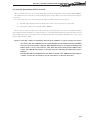
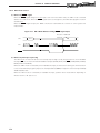
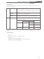
10.1.5 Hardware STOP mode
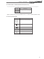
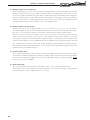
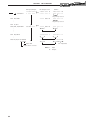
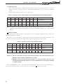
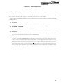
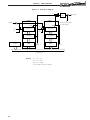
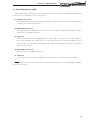
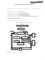
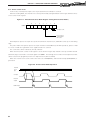
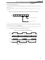
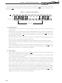
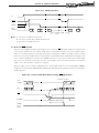
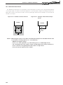
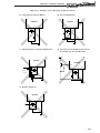
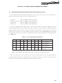
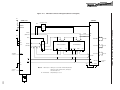
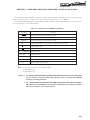
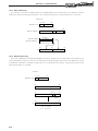
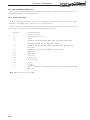
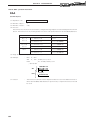
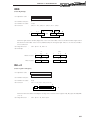
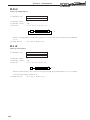
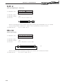
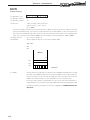
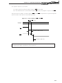
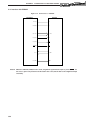
When the STOP signal changes from the high to low level, the hardware STOP mode is set. In this mode all clocks
stop. When the hardware STOP mode is set, program execution stops and the on-chip RAM contents just before
stoppage are retained, and the STOP signal used to release the hardware STOP mode is valid. All other functions
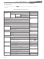
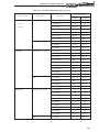
stop and the reset state is set. In the hardware STOP mode, the µPD78C18 output pins become high-impedance.
However, the port output latch values are retained.
Cautions
1. Crystal oscillation or ceramic oscillation should be used when using the hardware STOP
mode. The hardware STOP mode must not be used when an external clock is input.
2. The STOP mode is entered at a machine cycle boundary. Thus memory contents are not
corrupted, but the STOP mode may be entered midway through execution of an instruction.
Therefore, with instructions which perform a 16-bit data transfer the STOP mode may be
entered after only 8 bits have been transferred, with the transfer of the remaining 8 bits
incomplete (16-bit data transfer instructions and call instructions).
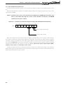
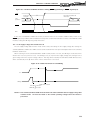
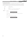
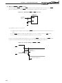
3. If the STOP signal is input (high low level) during reset input (RESET = low level), a transition
is made from the reset state to the STOP mode.
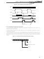
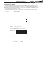
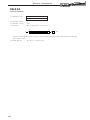
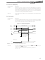
4. The STOP pin must be driven high after powering-on. The reset will not function correctly
if the STOP pin is left low. The STOP pin can be driven low after oscillator operation has
stabilized.
177