1
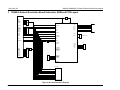
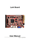
Simplifying System IntegrationTM
78Q8430
ARM9(920T) Embest Evaluation Board
User Manual
May, 2008
Rev. 1.0
UM_8430_007
78Q8430 ARM9(920T) Embest Evaluation Board User Manual
UM_8430_007
© 2008 Teridian Semiconductor Corporation. All rights reserved.
Teridian Semiconductor Corporation is a registered trademark of Teridian Semiconductor Corporation.
Simplifying System Integration is a trademark of Teridian Semiconductor Corporation.
ARM9 is a trademark of ARM Limited.
Linux is the registered trademark of Linus Torvalds.
Pentium is a registered trademark of Intel Corporation.
All other trademarks are the property of their respective owners.
Teridian Semiconductor Corporation makes no warranty for the use of its products, other than expressly
contained in the Company’s warranty detailed in the Teridian Semiconductor Corporation standard Terms
and Conditions. The company assumes no responsibility for any errors which may appear in this
document, reserves the right to change devices or specifications detailed herein at any time without
notice and does not make any commitment to update the information contained herein. Accordingly, the
reader is cautioned to verify that this document is current by comparing it to the latest version on
http://www.teridian.com or by checking with your sales representative.
Teridian Semiconductor Corp., 6440 Oak Canyon, Suite 100, Irvine, CA 92618
TEL (714) 508-8800, FAX (714) 508-8877, http://www.teridian.com
2
Rev. 1.0
UM_8430_007
78Q8430 ARM9(920T) Embest Evaluation Board User Manual
Table of Contents
1 Introduction ......................................................................................................................................... 5 1.1 Package Contents......................................................................................................................... 6 1.2 Safety and ESD Notes .................................................................................................................. 7 1.3 System Hardware Requirements .................................................................................................. 7 1.4 System Software Requirements ................................................................................................... 7 2 System Setup ...................................................................................................................................... 8 2.1 Jumper and Dip Switch Settings ................................................................................................... 8 2.2 Connections .................................................................................................................................. 9 2.3 System Startup ........................................................................................................................... 10 3 78Q8430 Embest Evaluation Board Schematic, BOM and PCB Layout ...................................... 11 4 Ordering Information ........................................................................................................................ 20 5 Related Documentation .................................................................................................................... 20 6 Contact Information .......................................................................................................................... 20 Rev. 1.0
3
78Q8430 ARM9(920T) Embest Evaluation Board User Manual
UM_8430_007
Figures
Figure 1: 78Q8430 System Interface Diagram ............................................................................................. 6 Figure 2: 78Q8430 Embest Evaluation Board Jumper Locations ................................................................. 8 Figure 3: 78Q8430 Embest Evaluation System Hardware Connections ...................................................... 9 Figure 4: Bus Interface Block Diagram ....................................................................................................... 11 Figure 5: Bus Interface Schematic .............................................................................................................. 12 Figure 6: MICTOR Diagnostic Connectors Schematic ............................................................................... 13 Figure 7: MAC Interface Schematic ............................................................................................................ 14 Figure 8: PHY Interface Schematic ............................................................................................................. 15 Figure 9: Top Silkscreen Layout ................................................................................................................. 17 Figure 10: Top Layer Layout ....................................................................................................................... 17 Figure 11: VCC Layer Layout ..................................................................................................................... 18 Figure 12: Ground Layer Layout ................................................................................................................. 18 Figure 13: Bottom Layer Layout .................................................................................................................. 19 Figure 14: Bottom Silkscreen Layout .......................................................................................................... 19 Tables
Table 1: 78Q8430 Embest Evaluation Board Jumper Settings .................................................................... 8 Table 2: 78Q8430 Embest Evaluation Board Bill of Materials .................................................................... 16 Table 3: Order Number and Part Description ............................................................................................. 20 4
Rev. 1.0
UM_8430_007
78Q8430 ARM9(920T) Embest Evaluation Board User Manual
1 Introduction
The 78Q8430 Embest Evaluation Board (D8430T3A_EB) is a design example for a 10/100BASE-TX
MAC+PHY Embest S3CEB2410 daughter card. The D8430T3A_EB plugs directly into the Embest
S3CEB2410 (ARM9™ based) motherboard. The network connection is provided by the 78Q8430 which is
a single chip auto-sensing, auto-switching (auto-negotiation or parallel detect modes and auto-MDIX)
10/100BASE-TX Fast Ethernet transceiver with full duplex operation capability. The device is designed
specifically for the Audio/Visual (A/V) and Set Top Box (STB) markets and is easily interfaced to available
A/V and STB core processors.
The 78Q8430 is compliant with applicable IEEE-802.3 standards. MAC and PHY configuration and
status registers are provided as specified by IEEE802.3u. The integrated MAC is supported by an
internal 32KByte transmit and receive SRAM FIFO. The partition of transmit and receive queues is
configurable through software, allowing the 78Q8430 to be tuned for specific applications. The device
contains hardware support for TCP-IP checksum and ARC address recognition.
The D8430T3A_EB provides support for the following 78Q8430 hardware interface features:
•
•
•
•
•
•
•
The system bus interface operates like external memory with an active low chip select.
Supports asynchronous big endian bus format.
Supports asynchronous 100 MHz operation.
Supports 32-bit wide data bus.
Optional EEPROM interface for configuration data.
Two programmable LED outputs for PHY status.
Single +3.3V power supply voltage with a common ground plane.
A host processor interfaces directly to the FIFO via the Global Bus Interface (GBI). The D8430T3A_EB is
configured for 32-bit big endian bus format. Figure 1 shows the 78Q8430 system interfaces.
Rev. 1.0
5
78Q8430 ARM9(920T) Embest Evaluation Board User Manual
32-bit/16-bit/8-bit
System
Bus
78Q8430
Single Chip
10/100 Ethernet
MAC & PHY
Interface
Configuration
EEPROM
Interface
UM_8430_007
LED
Link (Programmable)
LED
Activity (Programmable)
RJ45
CAT5
Cable
Integrated RJ-45
with 1:1
Transformer
JTAG
Interface
Figure 1: 78Q8430 System Interface Diagram
This document describes the setup and configuration of the 78Q8430 Embest Evaluation Board. The
evaluation board requires operation with a +3.3 V power supply sourced from the Embest bus interface
on the S3CEB2410 evaluation board. The 78Q8430 PHY interfaces to a CAT5 UTP cable via a 1:1
transformer.
The supplied software driver includes support for the Linux® operating system. The included 78Q8430
Software Driver Development Guidelines and 78Q8430 ARM9 Linux Driver User and Test Guide
documents describe the software interfacing requirements for quick driver integration and prompt system
evaluation of the 78Q8430.
Use this document with those listed in the Related Documentation section.
1.1
Package Contents
The 78Q8430 Embest Evaluation Board kit includes:
•
•
•
•
A 78Q8430 Embest Evaluation Board (D8430T3A_EB).
The Embest ARM9 S3CEB2410 evaluation platform.
A memory card containing the 78Q8430 Linux software device driver and supporting tools.
The following documents on CD:
• 78Q8430 ARM9(920T) Embest Evaluation Board User Manual (this document)
• 78Q8430 Preliminary Data Sheet
• 78Q8430 Layout Guidelines
• 78Q8430 Software Driver Development Guidelines
• 78Q8430 78Q8430 Driver Guide for ARM920T Linux
• 78Q8430 ARM9(920T) Linux Driver Diagnostic Guide
The printed circuit board Gerber files are available upon request.
6
Rev. 1.0
UM_8430_007
1.2
78Q8
8430 ARM9(9
920T) Embestt Evaluation Board
B
User Manual
M
Sa
afety and ESD
E
Notes
Connectin
ng live voltage
es to the evaluation system
m will result in
n potentially hazardous
h
volltages on the
boards.
The evaluation boards are
e ESD sensitive! ESD pre
ecautions musst be taken when handling
s!
these boards
1.3
Sy
ystem Hard
dware Requ
uirements
The follow
wing describes the minimum hardware requirements
r
for the 78Q8430 Embest Evaluation Bo
oard
system:
•
•
•
1.4
7
Emb
best Evaluatio
on Board (D84
430T3A_EB).
The 78Q8430
The Embest
E
ARM9
9 S3CEB2410
0 evaluation platform.
p
A PC to serve as th
he Linux hostt and control the
t ARM9 S3
3CEB2410 pla
atform.
Sy
ystem Softw
ware Requ
uirements
The follow
wing describes the minimum software re
equirements for
f evaluating
g the 78Q8430
0 Embest
Evaluation
n Board:
•
•
nux 2.6.13 drivver, version 1.1.
78Q8430 ARM Lin
6.13.
Linux operating system supportting kernel 2.6
Rev. 1.0
7
78Q8430 ARM9(920T) Embest Evaluation Board User Manual
UM_8430_007
2 System Setup
2.1
Jumper and Dip Switch Settings
The 78Q8430 Embest Evaluation Board utilizes several jumpers (JA, JC and J12 through J15) for
establishing the startup configuration of the 78Q8430 device. Figure 2 shows the location of the jumpers.
Table 1 describes the jumper options. The jumper numbers and settings are printed on the board.
Figure 2: 78Q8430 Embest Evaluation Board Jumper Locations
Table 1: 78Q8430 Embest Evaluation Board Jumper Settings
Jumper
J15
JA
Name
Setting
Description
CLKMODE
Selection
GND
Internal clock.
3P3V
External clock (default).
Chip Select Source
CS0
Selects the source for the 78Q8430 chip select
signal. The default setting is CS5.
CS1
CS2
CS3
CS4
CS5
J12
J13
J14
8
Interrupt Selection
INT5
INT6
INT7
INT8
INT9
INT16
INT17
INT18
Selects the destination for the 78Q8430 Interrupt
signal. The default setting is INT16.
Rev. 1.0
UM_8430_007
Jumper
JC
78Q8430 ARM9(920T) Embest Evaluation Board User Manual
Name
Clock Source
Setting
CLK1
CLK0
Description
Selects the source for the 78Q8430 clock.
The default setting is CCLK.
VCLK
SCLK
CCLK
2.2
Connections
Connect the system components as shown in Figure 3. Refer to the Embest S3CEB2410 documentation
for additional information on the connections for that platform.
Figure 3: 78Q8430 Embest Evaluation System Hardware Connections
STEP 1: Attach the 78Q8430 Embest Evaluation Board to the S3CEB2410 Evaluation Board via the three
connectors on the bottom of the 78Q8430 evaluation board.
STEP 2: Connect the 78Q8430 Embest Evaluation Board Ethernet port to the Linux PC using a CAT-5
cable.
STEP 3: Connect a serial console cable from the Linux Host PC serial port to the S3CEB2410 board
serial port.
STEP 4: Insert the memory card containing the 78Q8430 Linux software device driver into the memory
card slot on the S3CEB2410 board.
Rev. 1.0
9
78Q8430 ARM9(920T) Embest Evaluation Board User Manual
2.3
UM_8430_007
System Startup
STEP 1: On the Linux Host, set the testing port IP address to 192.168.10.100 (the S3CEB2410 platform
boots with IP address 192.168.10.99).
STEP 2: Open a full height xterm or kconsole window on the Linux Host.
STEP 3: Start minicom on the Linux Host at the xterm/kconsole command prompt:
~# minicom
STEP 4: Turn on the S3CEB2410 board power. Refer to the S3CEB2410 documentation for additional
information. The 78Q8430 Embest Evaluation Board receives its power through the Embest bus interface
on the S3CEB2410 Evaluation Board.
STEP 5: Boot the S3CEB2410 Board. Console messages must appear in the minicom window after
power on.
▪ Hit the space bar at the first boot prompt
▪ Respond with: cpu set 200 2
▪ On the next prompt, respond: boot
STEP 6: When boot up completes, enter the following at the prompt:
arp -s 192.168.10.100 00:0E:2E:5B:25:86
STEP 7: On the Linux Host, issue the following ping command to verify the connection to the target:
ping 192.168.10.99
10
Rev. 1.0
UM_8430_007
78Q8430 ARM9(920T) Embest Evaluation Board User Manual
3 78Q8430 Embest Evaluation Board Schematic, BOM and PCB Layout
JP
VCC33
CLK0
CLK1
VDCLK
CDCLK
SDCLK
NRESET
NGCS0
NGCS1
NGCS2
NGCS3
NGCS4
NGCS5
L1
JC
BUSCLK
VCCD
RESETB
JA
CSB
OEB
WRB
ADDR9:0
BNOE
BNWE
DATA31:0
AB9:0
MEMWAIT
MEMWAIT
R43
TXP
TXN
RXP
RXN
RJ45
XTLN
XTLP
25MHz Crystal
PMEB
ENDIAN0
ENDIAN1
S3CEB2410
INTERFACE
J2
LED0
LED1
INTB
DB31:0
BINT5
BINT6
BINT7
BINT8
BINT9
BINT16
BINT17
BINT18
BINT19
VCCA
BUSMODE
CLKMODE
WAITMODE
BOOTSZ0
BOOTSZ1
J12-J14
R42
U4
TCLK
TRST
TMS
TDO
TDI
J1
PROMCLK
PROMCS
PROMDO
PROMDI
78Q8430B
TP2 & TP5
Mictor Connectors
Logic Analyzer Pods
Figure 4: Bus Interface Block Diagram
Rev. 1.0
11
78Q8430 ARM9(920T) Embest Evaluation Board User Manual
UM_8430_007
BNOE
BNWE
NRESET
NGCS3
NGCS4
NGCS5
MEMWAIT
3P3V
1
2
3
JA2
CON3
JA3
CON3
NGCS[5:0]
VCLKP
C4
10
0805
R3
33
0603
3P3V
GND
AB1
AB3
AB5
AB7
AB9
DB2
DB0
DB5
DB7
DB9
DB11
DB13
DB15
DB30
DB28
DB26
DB24
DB22
DB20
DB18
DB16
GND
GND
GND2
1
1
GND
GND
BNWE
NRESET
MEMWAIT
C3
10
0805
GND
NGCS2
NGCS3
BINT6
BINT5
BINT7
AB0
AB2
AB4
AB6
AB8
R4
33
DB3
DB1
DB4
DB6
DB8
DB10
DB12
DB14
DB31
DB29
DB27
DB25
DB23
DB21
DB19
DB17
CLKOUT0
0603
BINT8
R5
33
CLKOUT1
0603
BINT17
BINT9
1
3
5
7
9
11
13
15
17
19
21
23
25
27
29
31
33
35
37
39
41
43
45
47
49
51
53
55
57
59
61
63
65
67
69
71
73
75
77
79
1
3
5
7
9
11
13
15
17
19
21
23
25
27
29
31
33
35
37
39
41
43
45
47
49
51
53
55
57
59
61
63
65
67
69
71
73
75
77
79
2
4
6
8
10
12
14
16
18
20
22
24
26
28
30
32
34
36
38
40
42
44
46
48
50
52
54
56
58
60
62
64
66
68
70
72
74
76
78
80
2
4
6
8
10
12
14
16
18
20
22
24
26
28
30
32
34
36
38
40
42
44
46
48
50
52
54
56
58
60
62
64
66
68
70
72
74
76
78
80
GND
PIN HEADER 40x2
EBS40X2
Mount Solder Side
1.27x1.27 ST HDR
MilMax 852-10-80-10-001
Mouser 575-002101 (2x50 pins)
GND1
3P3V
PIN HEADER 40x2
EBS40X2
CLK1
CLK0
VCLK
AB[9:0]
CSB
J12
CON4
CON4
BINT18
J13
CON4
R6
33
0603
CDCLK
BINT16
SDCLK
GND
PIN HEADER 40x2
EBS40X2
CSB
3P3V
NGCS0
NGCS1
NGCS2
2
4
6
8
10
12
14
16
18
20
22
24
26
28
30
32
34
36
38
40
42
44
46
48
50
52
54
56
58
60
62
64
66
68
70
72
74
76
78
80
INTRB
INTRB
R7
33
0603
J14
CCLK
SCLK
1
2
3
3P3V
2
4
6
8
10
12
14
16
18
20
22
24
26
28
30
32
34
36
38
40
42
44
46
48
50
52
54
56
58
60
62
64
66
68
70
72
74
76
78
80
3P3V
JC1
CON3
1
2
3
NGCS5
NGCS4
NGCS0
NGCS1
1
3
5
7
9
11
13
15
17
19
21
23
25
27
29
31
33
35
37
39
41
43
45
47
49
51
53
55
57
59
61
63
65
67
69
71
73
75
77
79
(J307)
JC2
CON3
1
2
3
BNOE
1
3
5
7
9
11
13
15
17
19
21
23
25
27
29
31
33
35
37
39
41
43
45
47
49
51
53
55
57
59
61
63
65
67
69
71
73
75
77
79
JP3
BINT9
BINT16
BINT17
BINT18
2
4
6
8
10
12
14
16
18
20
22
24
26
28
30
32
34
36
38
40
42
44
46
48
50
52
54
56
58
60
62
64
66
68
70
72
74
76
78
80
3P3V
(J301)
1
2
3
4
2
4
6
8
10
12
14
16
18
20
22
24
26
28
30
32
34
36
38
40
42
44
46
48
50
52
54
56
58
60
62
64
66
68
70
72
74
76
78
80
JP2
1
2
3
4
1
3
5
7
9
11
13
15
17
19
21
23
25
27
29
31
33
35
37
39
41
43
45
47
49
51
53
55
57
59
61
63
65
67
69
71
73
75
77
79
3P3V
1
2
3
4
3P3V
(J302)
BINT5
BINT6
BINT7
BINT8
JP1
1
3
5
7
9
11
13
15
17
19
21
23
25
27
29
31
33
35
37
39
41
43
45
47
49
51
53
55
57
59
61
63
65
67
69
71
73
75
77
79
JA1
CON3
1
2
3
C2
10
0805
GND
1
2
3
3P3V
JC3
CON3
BUSCLK
BUSCLK
AB[9:0]
DB[31:0]
DB[31:0]
Figure 5: Bus Interface Schematic
12
Rev. 1.0
UM_8430_007
78Q8430 ARM9(920T) Embest Evaluation Board User Manual
TP2
2
4
6
8
10
12
14
16
18
20
22
24
26
28
30
32
34
36
38
TP26
1
TP3
1
AB[9:0]
AB9
AB8
AB7
AB6
AB5
AB4
AB3
AB2
AB1
AB0
AB[9:0]
GND
GND
GND
43
40
39
NC
NC
CLKO
D15O
D14O
D13O
D12O
D11O
D10O
D9O
D8O
D7O
D6O
D5O
D4O
D3O
D2O
D1O
D0O
42
BNOE
BNWE
CSB
NRESET
GND
BNOE
BNWE
CSB
NRESET
PMEB
INTRB
MEMWAIT
NC
GND
CLKE
D15E
D14E
D13E
D12E
D11E
D10E
D9E
D8E
D7E
D6E
D5E
D4E
D3E
D2E
D1E
D0E
GND
PMEB
INTRB
MEMWAIT
BUSCLK
41
BUSCLK
1
3
5
7
9
11
13
15
17
19
21
23
25
27
29
31
33
35
37
GND
Mictor 38 Pin Connector
AMP
2-767004-2
TP5
GND
2
4
6
8
10
12
14
16
18
20
22
24
26
28
30
32
34
36
38
DB15
DB14
DB13
DB12
DB11
DB10
DB9
DB8
DB7
DB6
DB5
DB4
DB3
DB2
DB1
DB0
(LSB)
GND
43
GND
42
39
GND
NC
NC
CLKO
D15O
D14O
D13O
D12O
D11O
D10O
D9O
D8O
D7O
D6O
D5O
D4O
D3O
D2O
D1O
D0O
GND
DB31
DB30
DB29
DB28
DB27
DB26
DB25
DB24
DB23
DB22
DB21
DB20
DB19
DB18
DB17
DB16
NC
GND
CLKE
D15E
D14E
D13E
D12E
D11E
D10E
D9E
D8E
D7E
D6E
D5E
D4E
D3E
D2E
D1E
D0E
GND
TP55
41
(MSB)
1
40
1
1
3
5
7
9
11
13
15
17
19
21
23
25
27
29
31
33
35
37
GND
TP6
Mictor 38 Pin Connector
AMP
2-767004-2
DB[31:0]
DB[31:0]
Figure 6: MICTOR Diagnostic Connectors Schematic
Rev. 1.0
13
78Q8430 ARM9(920T) Embest Evaluation Board User Manual
3P3V
UM_8430_007
3P3V
C6
10
0805
GND
C7
0.1
0603
GND
C8
0.1
0603
GND
C9
0.1
0603
GND
C10
0.1
0603
GND
C11
0.1
0603
GND
C12
0.1
0603
GND
3P3V
R55
1K
0603
BUSCLK
15
NRESET
7
CSB
BNWE
BNOE
AB[9:0]
CSB
BNWE
BNOE
AB[9:0]
AB9
AB8
AB7
AB6
AB5
AB4
AB3
AB2
AB1
AB0
R66 33
R65 33
R64 33
16
11
12
R63
R62
R61
R60
R59
R58
R57
R54
R53
R52
25
24
23
22
21
20
19
18
9
10
33
33
33
33
33
33
33
33
33
33
80
79
3P3V
J15
83
84
85
3P3V
1
2
3
CON3
GND
PROMCLK
PROMCS
PROMDO
PROMDI
3
R56
10K
0603
CLK
CS
DI
GND
1
5
2
VCC
8
3P3V
DO
NC1
NC2
4
7
6
U4
93LC46B
SOIC8
TDI
TDO
TMS
TRST
TCLK
GND
100
1
74
75
76
77
4
81
3
5
6
BUSCLK
RESETB
DATA31
DATA30
DATA29
DATA28
DATA27
DATA26
DATA25
DATA24
DATA23
DATA22
DATA21
DATA20
DATA19
DATA18
DATA17
DATA16
DATA15
DATA14
DATA13
DATA12
DATA11
DATA10
DATA9
DATA8
DATA7
DATA6
DATA5
DATA4
DATA3
DATA2
DATA1
DATA0
CSB
WRB
OEB
ADDR9
ADDR8
ADDR7
ADDR6
ADDR5
ADDR4
ADDR3
ADDR2
ADDR1
ADDR0
ENDIAN1
ENDIAN0
BUSMODE
WAITMODE
CLKMODE
BOOTSZ1
BOOTSZ0
PROMCLK
PROMCS
PROMDO
PROMDI
TDI
TDO
TMS
TRST
TCLK
U2A
78Q8430B-100
MEMWAIT
INTB
PMEB
MEMWAIT
13
69
68
67
66
65
64
63
62
59
58
57
56
55
54
53
52
49
48
47
46
45
42
41
40
39
38
33
32
31
30
29
28
DATA31
DATA30
DATA29
DATA28
DATA27
DATA26
DATA25
DATA24
DATA23
DATA22
DATA21
DATA20
DATA19
DATA18
DATA17
DATA16
DATA15
DATA14
DATA13
DATA12
DATA11
DATA10
DATA9
DATA8
DATA7
DATA6
DATA5
DATA4
DATA3
DATA2
DATA1
DATA0
72
73
MEMWAIT
DB[31:0]
DB[31:0]
R8
R9
R10
R11
R12
R13
R14
R15
R16
R17
R18
R19
R20
R21
R22
R23
R24
R25
R26
R27
R28
R29
R30
R31
R32
R33
R34
R35
R36
R39
R40
R41
33
33
33
33
33
33
33
33
33
33
33
33
33
33
33
33
33
33
33
33
33
33
33
33
33
33
33
33
33
33
33
33
0603
0603
0603
0603
0603
0603
0603
0603
0603
0603
0603
0603
0603
0603
0603
0603
0603
0603
0603
0603
0603
0603
0603
0603
0603
0603
0603
0603
0603
0603
0603
0603
(MSB)
(LSB)
DB31
DB30
DB29
DB28
DB27
DB26
DB25
DB24
DB23
DB22
DB21
DB20
DB19
DB18
DB17
DB16
DB15
DB14
DB13
DB12
DB11
DB10
DB9
DB8
DB7
DB6
DB5
DB4
DB3
DB2
DB1
DB0
3P3V
R37
1K
0603
R38
1K
0603
INTB
INTRB
GND1
GND2
GND3
GND4
GND5
GND6
GND7
GND8
GND9
GND11
NRESET
TMS
TDI
2
14
34
35
26
43
50
60
70
78
BUSCLK
VCC1
VCC2
VCC3
VCC4
VCC5
VCC6
VCC7
VCC8
VCC9
VCC11
8
17
36
27
37
44
51
71
61
82
C5
10
0805
GND
TRST
GND
TCLK
TDO
R44
10K
0603
R45
10K
0603
J1
1
2
3
4
5
6
7
8
9
10
R42
33
0603
PMEB
R43
33
0603
CON10
GND
Figure 7: MAC Interface Schematic
14
Rev. 1.0
INTRB
PMEB
UM_8430_007
3P3V
VCCA
C14
0.1
0603
GND
LED0
TXN
RXP
RXN
XTLP
GNDA2
GNDA3
99
91
GNDA1
XTLN
89
R51
680
0603
92
ACTIVE
90
LINK
97
TXOP
98
TXON
94
RXIP
93
RXIN
C16
0.1
0603
GND
14
VCCA1
LED1
TXP
U2B
78Q8430B-100
C15
0.1
0603
GND
96
GND
86
Use Zero Ohm Resistor
C13
10
0805
VCCA3
FERRITE
R_0805
R47
49.9
1%
0603
R48
49.9
1%
0603
R49
49.9
1%
0603
R50
49.9
1%
0603
9
10
J0011F01P TabUp
Pulse Engr
CGND3
23
RALED
RCLED RX/TX
1
2
3
4
5
6
7
8
11
12
87
XTLP
88
XTLN
1
C18
27PF
0603
Y1
25.000MHZ
50ppm
Raltron
GND L11B
C19
27PF
0603
GND
LCLED
LALED
Link
24
CGND4
C17
10
0805
GND
3
TD+
TDTDCT
CGND1
CGND2
RDCT
RD+
RD-
13
L1
95
3P3V
VCCA2
3P3V
78Q8430 ARM9(920T) Embest Evaluation Board User Manual
CGND
J2
CGND
R46
680
0603
Gnd pins 2 and 4
GND
3P3V
Figure 8: PHY Interface Schematic
Rev. 1.0
15
78Q8430 ARM9(920T) Embest Evaluation Board User Manual
UM_8430_007
Table 2: 78Q8430 Embest Evaluation Board Bill of Materials
Item Quantity
1
2
2
9
3
7
4
2
5
7
6
3
7
1
8
3
9
10
11
12
13
14
1
1
1
3
3
4
15
52
16
17
18
2
2
1
19
1
20
1
16
PCB
Part
Vendor
Footprint
Number
C18,C19
CAP., 27pF, 50V C_0603
C1608C0G1H270J TDK
C7-C12,C14-C16 CAP., 0.1uF,16V C_0603
ECJ-1VB1E104K
Panasonic
GRM21BR61A106
C2-C6,C13,C17
CAP.,10uF,10V C_0805
Murata
KE19L
TP3,TP6
CON1
Testpoint
5011
Keystone
Sullins
JA1-JA3,JC1-JC3,
SIP3
SIP\3P
PBC03SAAN
Electronics
J15
Corp
Sullins
J12,J13,J14
SIP4
SIP\4P
PBC04SAAN
Electronics
Corp
Sullins
J1
CON10
SIP\10P
PBC10SAAN
Electronics
Corp
852-10-100-10JP1-JP3
40-Pin Header
EBS40X2
Mill Max
001000
J2
Integrated RJ45 RJ45-INT J1011F01P
Pulse Eng
Y1
25MHz Crystal
XTAL-SMD ABMM-25MHz
Abracon
L1
Ferrite Bead
L_0805
MMZ2012S181A
TDK
R44,R45,R56
RES, 10k, 5%
R_0603
ERJ-3GEYJ103V
Panasonic
R37,R38,R55
RES, 1k, 1%
R_0603
ERJ-EEKF1001V
Panasonic
R47-R50
RES, 49.9, 1%
R_0603
ERJ-3EKF49R9V Panasonic
R3-R36,R39-R43,
R52,R53,R54,
RES, 33, 5%
R_0603
ERJ-3GEYJ330V
Panasonic
R57-R66
R46,R51
RES, 680, 5%
R_0603
ERJ-3GEYJ681V
Panasonic
TP2,TP5
Mictor 38-pin
MICTOR
2-767004-2
Tyco
L1
Ferrite Bead
L_0805
MMZ2012S181A
TDK
Teridian
U2
78Q8430
100 LQFP 78Q8430
Semiconductor
U4
93LC46
SOIC8
93LC46BT-I/SN
Microchip
Reference
Part
Rev. 1.0
UM_8430_007
78Q8430 ARM9(920T) Embest Evaluation Board User Manual
Figure 9: Top Silkscreen Layout
Figure 10: Top Layer Layout
Rev. 1.0
17
78Q8430 ARM9(920T) Embest Evaluation Board User Manual
UM_8430_007
Figure 11: VCC Layer Layout
Figure 12: Ground Layer Layout
18
Rev. 1.0
UM_8430_007
78Q8430 ARM9(920T) Embest Evaluation Board User Manual
Figure 13: Bottom Layer Layout
Figure 14: Bottom Silkscreen Layout
Rev. 1.0
19
78Q8430 ARM9(920T) Embest Evaluation Board User Manual
UM_8430_007
4 Ordering Information
Table 3 lists the order number for the 78Q8430 Embest Evaluation Board.
Table 3: Order Number and Part Description
Part Description
78Q8430 Embest Evaluation Board (D8430T3A_EB)
Order Number
EVM8430-ARM9
5 Related Documentation
The following 78Q8430 documents are available from Teridian Semiconductor Corporation:
78Q8430 Preliminary Data Sheet
78Q8430 Layout Guidelines
78Q8430 Software Driver Development Guidelines
78Q8430 Driver Guide for ST 5100/OS-20 with NexGen TCP/IP Stack
78Q8430 STEM Demo Board User Manual
78Q8430 Driver Guide for ARM920T Linux
78Q8430 ARM9(920T) Embest Evaluation Board User Manual
78Q8430 ARM9(920T) Linux Driver Diagnostic Guide
6 Contact Information
For more information about Teridian Semiconductor products or to check the availability of the 78Q8430,
contact us at:
6440 Oak Canyon Road
Suite 100
Irvine, CA 92618-5201
Telephone: (714) 508-8800
FAX: (714) 508-8878
Email: [email protected]
For a complete list of worldwide sales offices, go to http://www.teridian.com.
20
Rev. 1.0
UM_8430_007
78Q8430 ARM9(920T) Embest Evaluation Board User Manual
Revision History
Revision
1.0
Rev. 1.0
Date
May 6, 2008
Description
First Publication
21