1
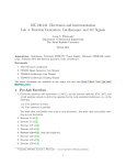
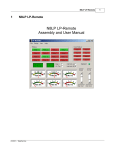
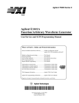
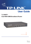
The Accutach Tachometer Calibrator/Tester Rev. 2
New and Improved to Work with Modern Computers
User’s Manual Revision 2.3
Copyright © 2011, 2012
Mark Olson
www.accutach.com
The Accutach Tachometer Calibrator/Tester User’s Manual
Table of Contents
Table of Contents................................................................................................................1
System Requirements..........................................................................................................2
Identifying Hardware Revisions..........................................................................................2
Installation Guide................................................................................................................3
Selecting a Power Supply...................................................................................................5
Connecting the CSC unit to an inductively coupled tachometer (In the car).....................5
Connecting the CSC to a direct coupled tachometer (In the car)....................................,..6
Connecting the CSC to an inductively coupled tachometer (On the bench)......................8
Connecting the CSC to a direct coupled tachometer (On the bench)……........................10
Connecting the CSC to a Honda/Mustang Tachometer & Speedometer (On the bench).12
Using the PC Digital Signal Processor Software..............................................................14
Using the Android FuncGen Software……………..........................................................18
Testing, Debugging or Calibrating Tachometers & Speedometers…..............................21
Bench power supply considerations.................................................................................22
Tachometer background information (Smiths)................................................................23
Troubleshooting...............................................................................................................25
How to get product support.............................................................................................29
Disclaimer:
This calibrator/tester was designed to work with inductively-coupled electronic tachometers such as
the Smiths type found in Jaguars, Sunbeam Alpines, Sunbeam Tigers and most other vintage British
sports cars. It was also designed to work with direct coupled tachometers as those found in 94-98
Ford Mustangs or 88-91 Honda Civics. This calibrator/tester was designed using techniques
designed to minimize any chance of causing any damage to your tachometer and/or PC. However,
Accutach is not responsible for any damage that might occur through the use or misuse of this
www.accutach.com to
product. Before you use this product, please check the Accutach web site (www.accutach.com)
see if there is any last minute information you may need to safely use this product. Feel free to
contact us before using this product on any tachometer should you feel unsure.
Page 1
The Accutach Tachometer Calibrator/Tester User’s Manual
The Accutach Tachometer Calibrator/Tester is designed to simulate high current automotive ignition
signals for the Smiths tachometer used in many British cars of the 1960s and 1970s. It is also designed to
simulate the voltage driven tachometer signals in more modern cars such as Ford Mustangs and Honda
Civics of the 1980s and 90s. It is designed to aid in debugging, repairing and calibrating tachometers. It
can also be used to calibrate some electronic speedometers as well.
System Requirements
The Accutach Tachometer Calibrator/Tester is a computer peripheral device. It relies on either a
Microsoft Windows-base personal computer or an Android handheld device running a freeware program
to operate. The computer must be an Intel compatible Personal Computer running Windows XP or
newer. The Android Device must run Android 1.6 or newer (tested with a Google Nexus 7 tablet). Either
device must have audio headphone output capability with a standard 3.5mm stereo headphone jack.
The PC software used in this system is freeware Digital Signal Generator software found at
http://heliso.tripod.com/download/generator/dsg.htm.
http://heliso.tripod.com/download/generator/dsg.htm We have not been able to contact the author, but
we thank him/her for making this software available for free.
The Android Software used in this system is freeware FuncGen SignalGenerator software from Crescendo
Systems, found here: https://play.google.com/store/apps/details?id=com.crescendosystems.afg&hl=en
Calibrator Components
Your Accutach Tachometer Calibrator/Tester consists of the following parts:
This User’s Manual (Download from www.accutach.com)
www.accutach.com
The CSC (Current Switching Circuit) Unit
0.1uF capacitor (for electronic speedometer calibration)
The following items are NOT included with the Calibrator/Tester:
Power supply
Intel compatible personal computer or Android device
Digital Signal Generator software
The power supply and personal computer can be purchased on-line or at a local electronic or computer
retail store. The Digital Signal Generator software can be downloaded from http://heliso.tripod.com/
download/generator/dsg.htm Should this link ever fail, please check the Accutach web site
download/generator/dsg.htm.
www.accutach.com
(www.accutach.com)
Identification of Hardware Revisions
The first revision of the Accutach Smiths Tachometer Calibrator can be identified by its 9-pin D serial
port connector. Revision 1 is now obsolete.
The second revision of the Accutach Smiths Tachometer Calibrator can be identified by its 35mm stereo
audio plug.
Page 2
The Accutach Tachometer Calibrator/Tester User’s Manual
PC Installation Guide:
This section of the instructions will tell you how to install the Digital Signal Generator software on your
personal computer and how to connect the Tachometer Calibrator/Tester CSC unit to your computer.
Installing the software on the computer:
Open a browser and navigate to http://heliso.tripod.com/download/generator/dsg.htm
http://heliso.tripod.com/download/generator/dsg.htm.
Click on the Press here to download. link. Save the file (generator.rar) to a folder of your choosing. A
.rar file is a compressed file similar to a .zip file. Now you will need to extract the program file from the
compressed file.
If your computer does not have a .rar file extractor, you can download the program
FreeRARExtractFrog from http://download.cnet.com/Free-RAR-Extract-Frog/3000-2250_410804840.html
10804840.html. Follow the instructions to install it.
Once you have the Digital Signal Generator .rar file saved, and have a .rar file extractor, extract the
generator.exe file from the generator.rar file and save it in any folder you’d like on your computer. We
recommend saving it to your desktop.
Once you have the generator.exe file on your computer, there is no further installation required. The
software will run when you double-click on the generator.exe file icon.
Connecting the CSC to the personal computer:
The Accutach Tachometer Calibrator/Tester Rev. 2 was designed to plug into a standard 3.5mm stereo
headphone jack on a personal computer. First, make sure that your audio is not muted and the volume
is set to maximum. Then simply plug the 3.5mm stereo headphone CSC plug into the jack.
Page 3
The Accutach Tachometer Calibrator/Tester User’s Manual
Android Installation Guide:
This section of the instructions will tell you how to install the Digital Signal Generator software on your
Android device and how to connect the Tachometer Calibrator/Tester CSC unit to your computer.
Installing the software on the Android device:
Open a browser and navigate to:
https://play.google.com/store/apps/details?id=com.crescendosystems.afg&hl=en.
Click on the Install link. The FuncGen Signal Generator application will be installed on your Android
device. The software will run when you tap on the FuncGen icon.
https://play.google.com/store/apps/details?id=com.crescendosystems.afg&hl=en
Connecting the CSC to the Android device:
The Accutach Tachometer Calibrator/Tester Rev. 2 was designed to plug into a standard 3.5mm stereo
headphone jack. First, make sure that your audio is not muted and the volume is set to maximum.
Then simply plug the 3.5mm stereo headphone CSC plug into the jack.
If your Android device is a cellular phone, you must buy a 2.5mm cell phone jack to 3.5mm stereo jack
adapter.
Plug in here
Page 4
The Accutach Tachometer Calibrator/Tester User’s Manual
Selecting a Power Supply
Most of the time, you will need a single well-regulated power supply that can supply up to one amp of current
in a square wave. This is true for all inductively coupled tachometers, and for direct coupled tachometers that
expect a signal that will go from 0 volts to the voltage that powers the tachometer. For example, a 12 volt
inductively coupled Smiths tachometer will need only a single 12V power supply. This is true for both
negative and positive ground tachometers.
Direct coupled tachometers that expect an input that goes from 0 volts to the power supply voltage (for
example 12V), then you will only need a single power supply.
A charged car or motorcycle battery makes a very good well-regulated power supply, Most tachometers use
a 12V supply voltage, although some may use a 6 volt supply. Battery chargers are not well enough
regulated, unless they are connected to a charged car of motorcycle battery.
Direct coupled tachometers that are powered by 12V, but expect a signal that is no larger than 0-5V will
require both a 12V power supply for the tachometer and a 5V power supply for the CSC unit.
The CSC unit will not work if powered by less than 5 volts and may be damaged if powered by more
than 12 volts.
It is a good idea to disconnect the CSC unit from power when it is powered at 12V and is not being
used. It generates nearly 10 Watts and it gets quite hot.
Connecting the CSC unit to a power supply:
There are three test leads coming out of the CSC unit. There is a black lead with a black clip (negative
power), a red lead with a red clip (positive power) and a lead with one color and a clip of the other color.
That lead is the directly coupled tachometer signal.
Connect the CSC unit red lead with the red clip to the positive terminal of the power supply and connect the
CSC unit black lead with the black clip to the negative terminal of the power supply. Be sure to check the
tachometer to see if it is a positive or negative ground unit before connecting it to its power supply, and
connect it accordingly.
Do not connect the CSC unit black lead with a red clip (or the red lead with a black clip) to anything unless
you are driving a directly coupled tachometer. See the directly coupled tachometer sections below to see how
to connect that lead.
Connecting the CSC unit to an inductively coupled tachometer (In the car)
An inductively coupled tachometer such as the Smiths tachometer used in Sunbeam products can be tested
and the calibration checked while it is still in the car. The CSC receives its power from the ignition wire.
The first step is to turn the car’s ignition key off and disconnect the ignition wire from the coil. DO NOT try
to run the calibrator/tester without disconnecting the ignition wire from the coil or you could destroy the CSC
unit. With a negative ground car, clip the red lead with the red clip to the ignition wire and clip the black lead
with the black clip to a convenient ground. With a positive ground car, clip the black cliplead to the ignition
wire and clip the red cliplead to a convenient ground. Do not let the third clip (the clip with one color and the
lead with the other color) touch anything or you can destroy the CSC unit. We normally leave this lead
clipped to the base of its own lead to keep it safe and out of the way.
Page 5
The Accutach Tachometer Calibrator/Tester User’s Manual
Warning: Make sure that the ignition wire and the red alligator clip do NOT touch ground
during testing and calibration, or whenever the ignition switch is on. If they do, you’ll be lucky if
you just blow a fuse in your car. If you are unlucky you may burn your car, garage and house
down. It’s a good idea to put a rag or some other electrical insulator under the alligator clip.
Also, needless to say, don’t do electrical work around gasoline fumes.
Double check the power connections before turning on the ignition key. You can now go to the section
entitled “Using the Digital Signal Generator Program”.
Warning: The CSC unit dissipates 9W at 12V, so it gets quite warm if used for a long period of
time with a 12V supply. This is normal, but you should exercise care when handling a hot CSC
unit to avoid discomfort or injury. It is a good idea to disconnect the CSC unit from power when
it is powered at 12V and is not being used.
Connecting the CSC to a direct coupled tachometer (In the car)
A direct coupled tachometer can also be tested and the calibration checked while it is still in the car.
Some may even be calibrated while still in the car. The first step is to turn the car’s ignition key off and
disconnect the tachometer wire from the coil or electronic ignition unit. DO NOT try to run the
calibrator/tester without disconnecting the tachometer wire from the coil or you could destroy the CSC
unit. With a negative ground car, clip the red lead with a red clip to the car’s positive power source
(ground on on positive ground car) and clip the black lead with a black clip to a the negative power
source (ground on a negative ground car). Some more modern tachometers may expect a 0-5V signal, in
which case you must power the CSC unit with a 5V well regulated bench power supply. Clip the black
lead with the red clip (some units have a red lead with a black clip) to the tachometer wire.
Warning: Make sure that the tachometer wire and the alligator clip do NOT touch ground during
testing and calibration. It’s a good idea to put a rag or some other electrical insulator under the
alligator clip. And, needless to say, don’t do electrical work around gasoline fumes.
Warning: The CSC unit generates a direct coupled tachometer signal that varies between 0 and
the voltage that your power supply provides. If your direct coupled tachometer needs a 0-5V
input signal, make sure you use a 5 volt power supply to power the CSC unit. If you power the
CSC unit with a 12V supply, it will generate a 0-12V signal. If your direct coupled tachometer
requires a 0-12V input signal, make sure you use a 12 volt power supply to power the CSC unit.
Some tachometers can handle either 0-5v or 0-12V signals It is your responsibility to ensure that
the signal from the CSC unit to the input of your direct coupled tachometer will not damage it..
Double check the power connections before turning on the ignition key. You can now go to the section
entitled “Using the Digital Signal Generator Program”.
Warning: The CSC unit dissipates 9W at 12V, so it gets quite warm if used for a long period of
time with a 12V supply. This is normal, but you should exercise care when handling a hot CSC
unit to avoid discomfort. It is a good idea to disconnect the CSC unit from power when it is
powered at 12V and is not being used.
Page 6
The Accutach Tachometer Calibrator/Tester User’s Manual
Connecting the CSC to an inductively coupled tachometer (On the bench)
You will need to obtain some sort of power supply in order to test or calibrate tachometers on the bench.
Please refer to the section entitled “Selecting a Power Supply” for a discussion of suitable and nonsuitable bench power supplies.
When removing the tachometer from the dash, be careful not to lose the knurled nut, lockwasher and
“U” shaped metal bracket that hold the ignition wire loop to the back of the tachometer. Leave any
plastic material holding the ignition wire in a loop on the wire. Be sure to take the “U” bracket with the
tachometer as they are required for calibration. Do not lose the nut and lockwasher that holds the
bracket.
First, put one leg of the tachometer’s “U” shaped bracket through the loop in the CSC unit’s red cliplead
wire as shown in the drawing.
With the wire loop through the “U” shaped bracket, attach it to the back of the tachometer. Attach the
red cliplead to the 5V to 12V power supply for the CSC unit. Attach the CSC unit’s black cliplead to the
supply’s ground connection. If the tachometer is a negative ground unit, attach the 12V tachometer
power supply to the bayonet connector on the back of the case and attach the tachometer power supply
ground to the case, or a ground connection if the case is removed. If the tachometer is a positive ground
unit, attach the tachometer power supply ground wire to the bayonet connector on the back of the case
and attach the 12V tachometer power supply to the case, or an internal ground connection if the case is
removed.
Page 7
The Accutach Tachometer Calibrator/Tester User’s Manual
Attach the red cliplead to the 5V or 12V power supply for the CSC unit. Attach the CSC unit’s black
cliplead to the supply’s ground connection. If the tachometer is a negative ground unit, attach the 12V
tachometer power supply to the bayonet connector on the back of the case and attach the tachometer
power supply ground to the case, or a ground connection if the case is removed.
CSC Unit Positive
Lead
CSC Unit Ground
Lead
Power Supply
Ground Lead
Power Supply
Positive Lead
Negative Ground
Tachometer
Screws attach
tachometer to case
If the tachometer is a positive ground unit, attach the tachometer power supply ground wire to the
bayonet connector on the back of the case and attach the 12V tachometer power supply to the case, or an
internal ground connection if the case is removed.
Power Supply
Positive Lead
CSC Unit Ground
Lead
CSC Unit Positive
Lead
Power Supply
Ground Lead
Positive Ground
Tachometer
Page 8
The Accutach Tachometer Calibrator/Tester User’s Manual
Connecting the CSC to a direct-connect Smiths tachometer (eg Series 3 E-type Jaguar)
Attach the red cliplead to the 12V (positive) power supply (regulated or battery) connection. Attach the
CSC black clip lead to the 12V power supply ground (negative) connection. Attach the 12V tachometer
power supply to the Tachometer power connector (Green wire in the case of the S-3 E-type Jag) and
attach the tachometer power supply ground to the case,or a ground connection if the case is removed.
Attach the CSC unit's Signal red lead with a black clip (or vice versa) to the tachometer input connection
(White wire with Blue stripe in the case of the S-3 E-type Jag). You can do the same connections at the
ballast resistor connector to check the calibration in the car, using any chassis ground:
Note the hole for accessing the calibration pot. If your tachometer has
this hole, you do not need to disassemble the tachometer to calibrate it.
Ground for the CSC unit
and the tachometer
Battery power for
The CSC unit and
the tachometer
CSC Calibration signal:
Red wire with Black clip or
Black Wire with Red clip
Note that I temporarily added a ground lug to the PCB mounting screw
to make it easier to ground the tachometer for debug and calibration.
Ground for the CSC unit
and the tachometer
CSC Calibration signal:
Red wire with Black clip or
Black Wire with Red clip
Battery power for
The CSC unit and
the tachometer
Page 9
The Accutach Tachometer Calibrator/Tester User’s Manual
If the Smiths tachometer needs to be taken out of its case for calibration or repair, do not pry the metal tabs on
the bezel or the bezel will never fit properly on the case again. Twist the bezel in either direction until the
slots in the case line up with the tabs on the bezel. The bezel, trim ring, gasket and glass can then be pulled
off the front of the case. It can be very difficult to break the bezel free. We use a pair of plastic handled
rubber strap wrenches to get the bezel to rotate on the case.
To remove the tachometer from the case, hold the power lug and “U” bracket stud between two fingers to hold
the tachometer in the case as you remove the two tachometer mounting screws on the rear of the case. Once
the two screws are removed, cup your other hand under the front of the tachometer to catch the face by its
edges as it falls out of the case when you release your two fingers from the back. Try not to let the weight of
the tachometer fall on the needle.
For inductively coupled tachometers the wire loop is set up the same with the tachometer out of the case as it
is in the case. The power lug is connected the same way out of the case as it is in the case. The case ground
connection is made to the end of the large resistor that connects the two tachometer circuit boards together.
Use the end of the resistor that is connected to the trace that goes to the metal frame of the tachometer.
Double check the power connections before turning on the power supplies. You can now go to the section
entitled “Using the Digital Signal Generator Program”.
Connecting the CSC to a direct coupled tachometer (On the bench)
You will need to obtain some sort of power supply in order to test or calibrate tachometers on the bench.
Please refer to the section entitled “Selecting a Power Supply” for a discussion of suitable and non-suitable
bench power supplies.
When removing the tachometer from the dash and/or the instrument cluster, be careful not to lose any of the
parts. The same care should be taken if the tachometer needs to be disassembled for calibration.
Attach the red cliplead to the +5V or +12V power supply for the CSC unit, depending on the input
requirements of the tachometer. Attach the CSC unit’s black cliplead to the supply’s ground connection.
If the tachometer is a negative ground unit, attach the tachometer power supply to the tachometer’s power
connection and attach the power supply’s ground to the tachometer’s ground. I do not know of any positive
ground direct coupled tachometers, but if you have one, attach the power supply ground wire to the
tachometer’s power connector and attach the +12V power supply to the case, or an internal ground connection
if the case is removed. 1971-1975 Series-3 E-type Jaguar tachometers are all negative ground tachometers
and should be connected as shown on the previous page.
Attach the black wire with the red cliplead to the tachometer’s ignition connector.
Double check the power connections before turning on the power supplies. You can now go to the section
entitled “Using the Digital Signal Generator Program”.
Page 10
The Accutach Tachometer Calibrator/Tester User’s Manual
Connecting the CSC to a direct coupled 88-91 Honda Civic/CRX tachometer (On the bench)
The Honda tachometer signal must be at least 5.7V in magnitude, and it can easily handle 12V. So you can
use one 12V power supply to calibrate these tachometers. Locate the tachometer power, ground and signal
terminals. Connect the power supply positive lead to the red CSC unit power lead, and the tachometer power
terminal. Connect the power supply negative lead to the black CSC unit power lead and the tachometer
ground terminal. Connect the CSC Unit tachometer lead (opposing colors lead) to the tachometer signal
terminal. We used red, black and green extension clipleads for power, ground and signal for convenience:
Signal
+12V Power
Ground
Connecting the CSC to a direct coupled 94-98 Ford Mustang tachometer (On the bench)
The Mustang tachometer signal must be at least 5.4V in magnitude, and it can easily handle 12V. So you can
use one 12V power supply to calibrate these tachometers. Locate the tachometer power, ground and signal
terminals. Connect the power supply positive lead to the red CSC unit power lead, and the tachometer power
terminal. Connect the power supply negative lead to the black CSC unit power lead and the tachometer
ground terminal. Connect the CSC Unit tachometer lead (opposing colors lead) to the tachometer signal
terminal. We used red, black and green extension clipleads for power, ground and signal for convenience:
Must also be grounded for a V8 tachometer. Leave
disconnected for a V6 tachometer
Signal
+12V Power
Ground
Page 11
The Accutach Tachometer Calibrator/Tester User’s Manual
Connecting the CSC to a 94-98 Ford Mustang Speedometer (On the bench)
The 94-98 Ford Mustang speedometer can be driven by the tester/calibrator as well. It expects an 8000 pulse
per mile AC signal. Locate the speedometer power, ground and signal terminals. There are 2 power terminals
for the Mustang Speedometer. Connect the power supply positive lead to the red CSC unit power lead, and
the 2 speedometer power terminals. Connect the power supply negative lead to the black CSC unit power lead
and the speedometer ground terminal. Connect the CSC Unit tachometer lead (opposing colors lead) to the
speedometer signal terminal through a 0.1uF capacitor. We used red, black and green extension clipleads for
power, ground and signal for convenience:
Power
Signal
Ground
Power
0.1uF capacitor
It is a good idea to disconnect the CSC unit from power when it is powered at 12V and is not being used.
It generates nearly 10 Watts and it gets quite hot.
Page 12
The Accutach Tachometer Calibrator/Tester User’s Manual
Using the Digital Signal Processor Personal Computer Software
Double-click on the generator.exe icon in the folder you extracted it to. You will see a window that looks like
this:
Square Wave
Sweep(Lin)
Settings
D/A Output
Add
Exit
You will only need to use five of the buttons: Square Wave, Sweep(Lin), Settings, D/A Output, Add and Exit.
Click on the Settings button. You will see a window that looks like this:
Page 13
The Accutach Tachometer Calibrator/Tester User’s Manual
Click on the down arrow next to the Type field and you will see a window like this:
Select Square Wave. You will see a window that looks like this:
Enter 100.0000 in the Fre1. box and click on the Set button. There is no reason to change any of the other
default settings. You will see a window that looks like this (don’t worry about the 0.1 in the Fre2. box.):
Click on the Close button.
Page 14
The Accutach Tachometer Calibrator/Tester User’s Manual
You will see a window that looks like this:
Click on the Add button until the waveform reaches its maximum size (maximum audio volume).
Click on the D/A Output button. You will see a window that looks like this:
Unplug the CSC unit from the PC’s headphone jack. Click on the Circle button. This will cause the PC to
make a continuous 100Hz buzzing sound from the speakers. (clicking the Single button will cause the PC to
make a 100Hz buzzing sound for 18 seconds only.) Make sure you maximize the volume before plugging the
CSC unit’s plug back into the PC’s headphone jack. At this point, you can power up the tachometer and the
CSC unit. You will be driving the tachometer with a 100Hz signal.
Click on the Close button to stop the signal. To restart the signal, click on the D/A Output button and then the
Circle button again.
Page 15
The Accutach Tachometer Calibrator/Tester User’s Manual
You must stop the signal by clicking on the Close button prior to changing the frequency of the signal. You
will again see a screen that looks like this:
Click on the Settings button. You will see a window that looks like this:
Enter 533.33333 in the Fre1. box, then click the Set button followed by the Close Button. Click on the
D/A Output button, and then click on the Circle button to start the signal generator running again.
If you unplug the CSC unit from the headphone jack you will hear a higher frequency (533Hz) buzz.
Page 16
The Accutach Tachometer Calibrator/Tester User’s Manual
Sweeping the Needle with a PC
It is often a good idea to sweep the needle to see if there are any RPMs at which the tachometer behaves
strangely.
To set up a sweep from one RPM to another, click on the Settings button to bring up the settings window:
Enter the frequency for the starting RPM in to the Freq1. box and for the ending RPM in the Freq2. box.
Click the Set button followed by the Close button. The signal generator is now set to sweep the needle. Click
on the D/A Output button to bring up this window: (Select sine wave to sweep speedometers and square wave
to sweep tachometers.)
Click on the Single button to sweep the needle once or click on the Circle button to sweep the needle
repeatedly.
Page 17
The Accutach Tachometer Calibrator/Tester User’s Manual
Using the Android FuncGen Signal Generator Software
Tap on the FuncGen icon. You will see a window that looks like this:
Square Wave
Sweep toggle
Frequency
Settings
...
Start
You will only need to use five of the functions: Square Wave, Frequency, Sweep, Settings and Start.
If you don’t want to sweep the tach, you can simply set the frequency at which you want to drive the tach,
select Square wave and tap start. If you want to sweep the tach, you will need to tap the three-dot settings
icon and then tap the Modulation Parameters icon. You will see a screen that looks like this:
Linear Sweep
Sweep Time
(seconds)
Starting Frequency
Page 18
Ending Frequency
The Accutach Tachometer Calibrator/Tester User’s Manual
To sweep the tach, you will need to tap the Linear button to select it. Then set the Time to 10, which tells the
software to sweep from the minimum frequency to the maximum prequency every 10 seconds. Set the
minimum and maximum frequencies you want to sweep between.
Linear Sweep
Sweep Time
(seconds)
Starting Frequency
Ending Frequency
Page 17
Tap on the Back icon to go back to the main screen. Tap OK if it notifies you that the parameters have been
reset. Tap Square, Sweep and Start to start to sweep the tach needle. (Note that this sweep sweeps the needle
up only, not up and then back down again.)
Square Wave
Sweep toggle
Page 19
Frequency
Settings
...
Start
The Accutach Tachometer Calibrator/Tester User’s Manual
Testing, Debugging or Calibrating Tachometers
Four stroke motors fire the ignition for one half of the cylinders during each revolution of the crankshaft. So
an 8 cylinder engine fires 4 times per rev, a 6 cylinder engine fires 3 times per rev, a 5 cylinder engine fires
2.5 times per rev and a 4 cylinder engine fires 2 times per rev.
Since there are 60 seconds in one minute, the tachometer signal frequency in Hz can be calculated using the
following formula:
Freq. = (RPM/60)* the number if ignition events per revolution.
4 cyl. freq. = RPM/30
5 cyl. freq. = RPM/24
6 cyl. freq. = RPM/20
8 cyl. freq. = RPM/15
10 cyl. freq. = RPM/12
12 cyl. freq. = RPM/10
This table tells you the frequencies to enter into the Digital Signal Generator in order to simulate ignition
signals at different RPMs:
RPM 4 cyl freq. 5 cyl freq. 6 cyl freq. 8 cyl freq. 10 cyl freq. 12 cyl freq.
500 16.66667 20.83333
25 33.33333 41.666667
50
1000 33.33333 41.66667
50 66.66667 83.333333
100
1500
50
62.5
75
100
125
150
2000 66.66667 83.33333
100 133.3333 166.66667
200
2500 83.33333 104.1667
125 166.6667 208.33333
250
3000
100
125
150
200
250
300
3500 116.6667 145.8333
175 233.3333 291.66667
350
4000 133.3333 166.6667
200 266.6667 333.33333
400
4500
150
187.5
225
300
375
450
5000 166.6667 208.3333
250 333.3333 416.66667
500
5500 183.3333 229.1667
275 366.6667 458.33333
550
6000
200
250
300
400
500
600
6500 216.6667 270.8333
325 433.3333 541.66667
650
7000 233.3333 291.6667
350 466.6667 583.33333
700
7500
250
312.5
375
500
625
750
8000 266.6667 333.3333
400 533.3333 666.66667
800
8500 283.3333 354.1667
425 566.6667 708.33333
850
9000
300
375
450
600
750
900
9500 316.6667 395.8333
475 633.3333 791.66667
950
10000 333.3333 416.6667
500 666.6667 833.33333
1000
10500
350
437.5
525
700
875
1050
11000 366.6667 458.3333
550 733.3333 916.66667
1100
To calibrate a tachometer, select the frequency that corresponds to the RPM you want for the engine the
tachometer is for, and start the signal generator. Power up the tachometer and the CSC unit The tachometer
needle should move somewhere on the tachometer face. At this point, turn the tachometer’s calibration
potentiometer until the needle points to the correct RPM for the frequency you chose.
Page 20
The Accutach Tachometer Calibrator/Tester User’s Manual
Testing, Debugging or Calibrating Speedometers
Many electronic speedometers depend on an vehicle speed signal, such as that in 1994-1998 Ford Mustangs.
The Mustang speed signal generates 8000 pulses per mile. Since there are 3600 seconds in an hour, and 8000
pulses in a mile, calibration frequencies can be calculated with this formula:
Freq. = (8000/3600)*MPH = 2.22222…*MPH
This table tells you the frequencies to enter into the Digital Signal Generator in order to simulate VSS signals
at different speeds:
MPH
Freq. Hz
10 22.22222
20 44.44444
30 66.66667
40 88.88889
50 111.1111
60 133.3333
70 155.5556
80 177.7778
MPH
Freq. Hz
90
200
100 222.2222
110 244.4444
120 266.6667
130 288.8889
140 311.1111
150 333.3333
160 355.5556
To calibrate a speedometer, select the frequency that corresponds to the speed you want, and start the signal
generator. Power up the speedometer and the CSC unit The speedometer needle should move somewhere on
the speedometer face. At this point, remove the speedometer’s needle and replace it on the speedometer shaft
so that it points to the correct speed for the frequency you chose.
You can drive the tachometer up to 180 degrees from the 0 MPH mark without problem. If you try to drive it
much more than 180 degrees, the needle will not move. If you drive it too close to 180 degrees, the needle
will go there, but peg the speedometer to the bottom of the pin when you turn off the calibrator. It can be
difficult to get it to move back to 0 MPH, so it is not advised to calibrate the speedometer above 180 degrees
from the 0 MPH mark.
Page 21
The Accutach Tachometer Calibrator/Tester User’s Manual
Bench power supply considerations
On the bench, you will need a good, well-regulated power supply to power the tachometer and
the CSC unit. The tachometer requires a well-regulated 12V supply while the CSC unit
requires a 5V to 12V supply.
I don’t have power consumption specifications for the tachometers, but they don’t seem to
require too much current to operate. However, it is very important that the 12V supply to the
tachometer be a very clean, steady 12V. Ripple or noise on the power signal will confuse the
tachometer completely. A 12 battery charger can’t be used, for example, because there is far
too much ripple in the power supply and it can’t respond well to sudden changes in current.
The CSC unit uses nearly 10 watts when it is not being driven by the computer. It is a good
idea to disconnect the CSC unit from power when it is powered at 12V and is not being
used. When the calibrator/tester is driving the tachometer with a signal, the CSC unit draws a
maximum current of 1/4 Amp if powered by a 5V supply to 1/2 Amps if powered by a 12V
supply. Clearly, the CSC unit will run considerably cooler when powered by a lower voltage
supply.
A charged 12V car battery is a very well-regulated power supply for bench testing tachometers.
An ideal bench setup is a small, regulated 12V supply for powering the tachometer and a
separate, larger well-regulated variable supply for powering the CSC unit.
The power supply in your computer should NOT be used, as the calibrator/tester could easily
overload your supply or inject noise into the system that could cause your computer to have
severe problems.
Page 22
The Accutach Tachometer Calibrator/Tester User’s Manual
Tachometer background information:
This section is intended to give you some background information on tachometers to enable you to
determine if the Accutach Tachometer Calibrator/Tester can help you calibrate your tachometer, help
you do calibration, and, if you are real adventuresome, help you repair broken tachometers.
I know of two types of electronic tachometers in cars, inductively coupled and direct coupled.
Direct connect electronic tachometers have a direct electrical connection to the ignition circuit.
These tachometers use voltage signals in the ignition circuit to drive the tachometer. Since there are
so many types of direct coupled tachometers, I can’t describe them all. Most of them need to be
disassembled in order to calibrate them. You need to look for an adjustment pot (or variable resistor)
used to calibrate the tachometer. You also need to ensure that a 12V signal on the input will not hurt
the device.
The inductively coupled type of tachometer uses a one turn loop of the ignition wire as the primary
side of a transformer that couples the current pulses caused by the car’s ignition circuit into the inside
of the tachometer. The timing of those current pulses are used to drive the tachometer. The
Accutach Tachometer Calibrator/Tester is designed to calibrate these type of tachometers.
While this calibrator/tester will work with any inductively coupled electronic tachometer, it was
developed and tested with Smiths tachometers from the mid 1960’s. These tachometers were used in
Sunbeam Tigers and Alpines as well as in Shelby Cobras and many other British cars of the period.
Since this is the tachometer I’ve had the most experience with, this is the tachometer I will describe
in detail.
The Smiths tachometer must be disassembled in order to calibrate or repair it. Carefully rotate the
chrome bezel until the tabs on the bezel line up with the slots on the case. This can be a very
difficult job if the seals have aged badly and stuck. Whatever you do, DON’T pry up the tabs on the
bezel or you’ll ruin it. We use a pair of plastic strap wrenches with rubber straps to rotate the tough
bezels. Don’t tap the bezel edge as the meter is very fragile.
Once you get the chrome bezel off the tachometer, the face glass and inside bezel must come out, if
they didn’t come out with the chrome bezel. Carefully pry the inner bezel from the case. It is not
necessary to separate the glass from either bezel if it is stuck to one of them. Be careful prying on
anything, especially if the glass is still in place, as it is very easy to damage it or the bezels. I have
not been able to locate a source for the seals, so I just try to be very careful, and reuse what I can
with what’s left of the seals. I always use a lint free cloth and glass cleaner to clean the glass while
the tachometer is apart.
Page 23
The Accutach Tachometer Calibrator/Tester User’s Manual
Once the meter face is exposed, be very careful not to mar or get finger prints on the face or break
the needle. The next step is to remove the tachometer innards from the case. There are four
screws on the back of the case, two of which are recessed in holes in the case and two of which are
not. The two in the recessed holes hold the innards of the tachometer together so don’t take them
out. Put the tachometer case face down on the bench. While pinching the “U” bracket stud with
one finger and the power spade lug with another to hold up the tachometer innards, remove both of
the non-recessed screws. The tachometer innards are now being held in the case by your two
fingers. Pick up the case and cup your other hand under the face of the case. Carefully let the stud
and spade lug slide out of your fingers and catch the face of the tachometer by the edges in the cup
of your hand. You can then pull the case off of the tachometer innards and turn it over. You are
now ready to calibrate or debug the tachometer.
This is a good time to slide a shield under the needle to shield the face and repaint the needle if
you can find appropriate paint. (My artistic talents aren’t very good, so I never try that step
myself.)
Reassembly is the reverse of this process.
Electronically, the Smiths tachometer is a relatively simple two Germanium transistor inductively
coupled electronic tachometer. The following diagram shows the schematic of the tachometer:
The two transistors together form a monostable multivibrator, or one-shot. Normally, the collector
of Q1 is at 6V. An ignition pulse couples through the transformer to trigger a one-shot voltage
pulse to 12V on the collector of Q1 for a set amount of time. Every time an ignition pulse is
detected through the transformer, the collector of Q1 will pulse from 6V to 12V for a fixed amount
of time. While the collector of Q1 is at 12V, the top of the meter is held at 6V by the Zener diode,
so current will flow through the meter, causing the needle to deflect. The width of the voltage
pulse is determined by the combination of the 0.25uF capacitor C2 and the combination of
resistors R3, R4 and pot. R5. The one-shot is triggered by every ignition pulse, so the voltage
waveform looks like a series of pulses when the engine is running. Since the pulses are fixed in
width and the frequency of the pulses is determined by the engine speed, the ratio of the time the
waveform is at 12V vs. 6V goes up with increases in engine speed and down with decreases in
engine speed. The way the meter works, the more time the waveform is at 12V, the more the
needle is deflected and the less time the waveform is at 12V, the less the needle is deflected.
To calibrate the meter, you want to drive the tachometer with a very accurate, known signal at the
correct frequency for the RPM reading that you want on the meter. Once you are driving the
tachometer with the accurate frequency, you can adjust the needle deflection to the proper place by
turning the calibration pot. R5. The tachometer can only be calibrated at one RPM. After that, all
you can do is check to see how close you are at other RPMs.
Page 24
The Accutach Tachometer Calibrator/Tester User’s Manual
It is possible to recalibrate the 7,000RPM Alpine 4 cylinder tachometers to work in V8 Tigers using
this method.
The most common failure modes I have seen are failure of the main timing capacitor C2. Failure of
this cap. has caused tachometers to be erratic, temperature sensitive or just plain dead. If you
suspect your tachometer to have this problem, locate the capacitor, carefully unsolder the capacitor,
and replace it with a new one. I have not been able to locate a supply of 0.25uF capacitors, but
available 0.22uF to 0.27uF capacitors work fine. I have yet to come across a tachometer with a
failed transistor, but they are rumored to cause problems as well. The other major failure
mechanism I have seen is a broken meter spring. The meter needs to be replaced in this case.
Replacement meters must be gotten from a parts tachometer. As a matter of course, the tachometer
will have to be recalibrated if any of the parts are replaced.
All of the Smiths tachometers of this era use the same electronic and mechanical design, regardless
of number of cylinders, positive or negative ground or the make of the car. The power and ground
wires are reversed between tachometers for positive or negative ground cars. The only other thing
that changes is the face used on the meters. So don’t throw away any vintage Smiths tachometers or
tachometer parts. They can be used to resurrect any other one.
Troubleshooting:
This section attempts to explain how to find problems with the Accutach Tachometer Calibrator/
Tester or your test setup.
If the tachometer is working in the car with the engine running, and you can’t get the calibrator to
work with a tachometer in the car, first double check the cliplead attachment to the ignition wire
and the ground, if it is an inductively coupled tachometer. If you are testing a direct coupled
tachometer, ensure you have a good power, ground and tachometer input connections. Make sure
they are connected correctly for positive or negative ground. Reclip the leads to ensure good
electrical connections. Make sure the cable from the CSC unit to the personal computer is well
seated.
If the tachometer worked in the car with the engine running, and doesn’t on the bench, check the
power supplies and polarities for both the tachometer and the CSC unit. Check to make sure you
have the loop in the red cliplead through the “U” bracket correctly on the back of the tachometer, if
it is an inductively coupled tachometer. Reclip the leads to ensure good electrical connections.
Make sure the cable from the CSC unit to the personal computer is well seated.
If the tachometer worked in the car with the engine running and it worked in the car with the
calibrator/tester, and it doesn’t work on the bench, double check the power connections. If you are
using a 5V supply for the CSC unit, try two loops through the “U” bracket if the tachometer is
inductively coupled.
If the tachometer didn’t work in the car and you want to ensure the calibrator/tester is working
correctly, you will probably need to use an oscilloscope on the bench to see if the signal is being
coupled through to the tachometer. If it isn’t, There could be a problem with the power
connections, the loop on the “U” bracket, or the COM port as above. If there is no problem there, it
could be the input transformer or transistor Q1.
Page 25
The Accutach Tachometer Calibrator/Tester User’s Manual
Page 26
The Accutach Tachometer Calibrator/Tester User’s Manual
For your reference, here are the schematics for the tachometer from the Series-3 E-type Jaguar from
1971 to 1975.
1971-1975 Series 3 E-type Jaguar Tachometer Schematics
Mark Olson
2012
68, 2W
R6
BLU
GRY
BLK
25K
8
2
7
3
6
4
5
Ground
(Case)
Package
Top
View
Page 27
R7
42
R8
R9
1
1
42
4.3K
R2
0.1uF
TI
MIC7/C
6
4.7K
YEL
ORN
RED
5
C3
U1
TI
MIC7/C
2
290
RED
WHT
BRN
Meter
C2
0.047uF
15K
YEL
VIO
RED
R3
D1
8
YEL
RED
BLK
YEL
RED
BLK
68
R1
3
4
C1
Tach Signal
White/Blue
BRN
GRN
ORN
R4
7
BLU
GRY
BLK
64uF, 15V
R5
Battery Voltage
Green
The Accutach Tachometer Calibrator/Tester User’s Manual
How to get product support:
The Accutach Tachometer Calibrator/Tester is a very robust design and should give you
years of very good service. If it breaks due to anything other than flagrant abuse, I’ll repair
it or replace it at my option for five years after purchase. You only need to pay the shipping
and handling both ways.
Before you send it back, write or give me a call to see if we can debug things first.
I can be reached for support in the following ways:
US Mail:
Mark Olson
5467 Glennan Ct.
San Jose, CA 95129
Internet:
Day Phone
[email protected]
1(408) 357-3541
Page 27