1
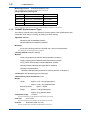
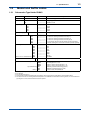
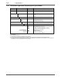
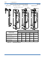
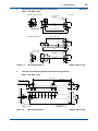
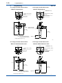
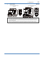
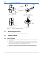
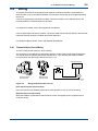
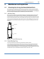
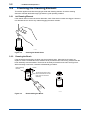
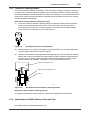
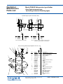
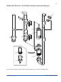
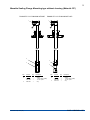
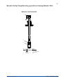
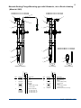
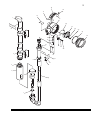
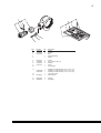
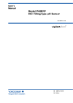
User’s Manual Model PH8HS, PH8HSF Submersion Type Holders IM 12B07M01-01E R IM 12B07M01-01E 4th Edition i <INTRODUCTION> INTRODUCTION This manual covers the PH8HS, PH8HSF Submersion Type Holders. Other related items are described in the following manuals: Model Title IM No. PH8ERP KCl Refillable type pH Sensor IM 12B7K1-02E PH8EFP KCl Filling type pH Sensor IM 12B7J1-01E PH8EHP pH Sensor for Pure Water IM 12B7J2-01E PH4,OR4 pH and ORP Sensors IM 12B10B00-01EN HA405 Solid Electrolyte (xerolyt) pH Sensor IM 12B7E1-01E HA406 Solid Electrolyte (xerolyt) pH Sensor with Temperature Element IM 12B07E02-01E DPA405 pH Sensor for Chemical Processes IM 12B7H1-01E DPA406 pH Sensor for Chemical Process with Temperature Element IM 12B07H02-01E HF405 Hydrofluoric Acid-resistive pH Sensor IM 12B07L01-01E FLXA202, FLXA21 2-Wire Liquid Analyzer IM 12A01A02-01E PH201G*B Distributor IM 19B1E4-02E PH450G pH/ORP Converter IM 12B07C05-01E PH202G, PH202S pH/ORP Transmitter IM 12B07D02-01E PUS400G Ultrasonic Oscillator IM 19C1B3-01E PH8USF, PH8AL Ultrasonic Oscillator (Explosionproof Type), Alarm Box IM 12B5U2-E WTB10-PH Terminal Box IM 19D01B01-01E PH8TBG Terminal Box IM 12B07W01-01E OR8EFG KCl Filling type OPR Sensor IM 12C07J01-01E OR8ERG KCl Refillable type OPR Sensor IM 12C04K01-01E OR8TBG Terminal Box IM 12C04W01-01E Media No. IM 12B07M01-01E 4th Edition : Nov. 2015 (YK) All Rights Reserved Copyright © 2004, Yokogawa Electric Corporation IM 12B07M01-01E ii <INTRODUCTION> For the safe use of this equipment n Safety, Protection, and Modification of the Product • In order to protect the system controlled by the product and the product itself and ensure safe operation, observe the safety precautions described in this user’s manual. We assume no liability for safety if users fail to observe these instructions when operating the product. • If this instrument is used in a manner not specified in this user’s manual, the protection provided by this instrument may be impaired. • Be sure to use the spare parts approved by Yokogawa Electric Corporation (hereafter simply referred to as YOKOGAWA) when replacing parts or consumables. • Modification of the product is strictly prohibited. n Notes on Handling User’s Manuals • Please hand over the user’s manuals to your end users so that they can keep the user’s manuals on hand for convenient reference. • Please read the information thoroughly before using the product. • The purpose of these user’s manuals is not to warrant that the product is well suited to any particular purpose but rather to describe the functional details of the product. • No part of the user’s manuals may be transferred or reproduced without prior written consent from YOKOGAWA. • YOKOGAWA reserves the right to make improvements in the user’s manuals and product at any time, without notice or obligation. • If you have any questions, or you find mistakes or omissions in the user’s manuals, please contact our sales representative or your local distributor. n Warning and Disclaimer The product is provided on an “as is” basis. YOKOGAWA shall have neither liability nor responsibility to any person or entity with respect to any direct or indirect loss or damage arising from using the product or any defect of the product that YOKOGAWA can not predict in advance. n Signal Words The following words are used in this manual. CAUTION This symbol gives information essential for understanding the operations and functions. NOTE This symbol indicates information that complements the present topic. IM 12B07M01-01E iii <INTRODUCTION> After-sales Warranty n Do not modify the product. n During the warranty period, for repair under warranty consult the local sales representative or service office. Yokogawa will replace or repair any damaged parts. Before consulting for repair under warranty, provide us with the model name and serial number and a description of the problem. Any diagrams or data explaining the problem would also be appreciated. • If we replace the product with a new one, we won’t provide you with a repair report. • Yokogawa warrants the product for the period stated in the pre-purchase quotation Yokogawa shall conduct defined warranty service based on its standard. When the customer site is located outside of the service area, a fee for dispatching the maintenance engineer will be charged to the customer. • Returned goods that have been in contact with process fluids must be decontaminated and disinfected prior to shipment. Goods should carry a certificate to this effect, for the health and safety of our employees. Material Safety Data sheets must be included for all components of the process to which the sensor have been exposed. n In the following cases, customer will be charged repair fee regardless of warranty period. • Failure of components which are out of scope of warranty stated in instruction manual. • Failure caused by usage of software, hardware or auxiliary equipment, which Yokogawa Electric did not supply. • Failure due to improper or insufficient maintenance by user. • Failure due to modification, misuse or outside-of-specifications operation which Yokogawa does not authorize. • Failure due to power supply (voltage, frequency) being outside specifications or abnormal. • Failure caused by any usage out of scope of recommended usage. • Any damage from fire, earthquake, storms and floods, lightning, disturbances, riots, warfare, radiation and other natural changes. n Yokogawa does not warrant conformance with the specific application at the user site. Yokogawa will not bear direct/indirect responsibility for damage due to a specific application. n Yokogawa Electric will not bear responsibility when the user configures the product into systems or resells the product. n Maintenance service and supplying repair parts will be covered for five years after the production ends. For repair for this product, please contact the nearest sales office described in this instruction manual. IM 12B07M01-01E v <CONTENTS> Model PH8HS, PH8HSF Submersion Type Holders IM 12B07M01-01E 4th Edition CONTENTS INTRODUCTION..............................................................................................i For the safe use of this equipment..............................................................ii After-sales Warranty....................................................................................iii 1. Specifications............................................................................................ 1-1 1.1 1.2 1.3 2. General Specifications...................................................................................... 1-1 1.1.1 PH8HS Submersion Type Holder....................................................... 1-1 1.1.2 PH8HSF (Explosionproof Type) ........................................................ 1-2 Model and Suffix codes..................................................................................... 1-3 1.2.1 Submersion Type Holder PH8HS....................................................... 1-3 1.2.2 Submersion Type Holder (Explosionproof Type) PH8HSF................ 1-4 External Dimensions......................................................................................... 1-5 Installation, Piping and Wiring................................................................. 2-1 2.1 Installing the Holder........................................................................................... 2-1 2.1.1 Shipping and Checking the Specifications ........................................ 2-1 2.1.2 Selecting the Holder Installation Site.................................................. 2-1 2.1.3 Installation Procedure......................................................................... 2-1 2.2 Mounting the Sensor ........................................................................................ 2-2 2.3 Cleaner Piping ................................................................................................... 2-2 2.3.1 Piping Precautions.............................................................................. 2-2 2.3.2 Piping Procedure................................................................................ 2-4 2.3.3 Installation of PH8PU1 Washer Pump and Water Tank..................... 2-4 2.4Wiring.................................................................................................................. 2-5 2.4.1 Solenoid Valve Circuit Wiring.............................................................. 2-5 2.4.2 Wiring for PH8PU1 Washer Pump and Tank...................................... 2-6 3.Maintenance/Inspection........................................................................... 3-1 3.1 3.2 Checking the O-ring that Seals Wetted Parts................................................. 3-1 3.1.1 pH Sensor O-ring............................................................................... 3-1 3.1.2 Cleaner Mounting O-ring.................................................................... 3-1 Checking the Cleaning Element....................................................................... 3-2 3.2.1 Jet Cleaning Element.......................................................................... 3-2 3.2.2 Cleaning the Brush............................................................................. 3-2 3.2.3 Ultrasonic Cleaning Element.............................................................. 3-3 3.2.4 Maintenance of PH8PU1 Washer Pump and Tank ........................... 3-3 IM 12B07M01-01E vi <CONTENTS> Customer Maintenance Parts List (PH8HS)...................... CMPL 12B05M01-03E Customer Maintenance Parts List (PH8HSF).................... CMPL 12B05M01-04E Revision Information................................................................................................i IM 12B07M01-01E 1. 1-1 < 1. Specifications > Specifications The Model PH8HS Submersion Type Holder is designed for use in open tanks, reactors, or wastewater drains, and allows the whole sensor to be submerged with only the sensor tip exposed to the solution. Holders with ultrasonic or brush cleaning options are available. The Model PH8HSF is a version with ultrasonic cleaning for high-pressure explosionproof applications. 1.1 General Specifications 1.1.1 PH8HS Submersion Type Holder Applicable sensors: General pH Sensor PH8ERP, PH8EFP Special pH Sensor HA405, DPA405, HF405 PH4 Sensor PH4P, PH4PT,PH4F, PH4FT,PH4C, PH4CT General ORP Sensor OR8ERG, OR8EFG Special ORP Sensor HA485, DPA485 OR4 Sensor OR4P, OR4C Note: An adapter is required when using special pH/ORP sensor or PH4/OR4 sensor. When using with special pH/ ORP sensor or PH4/OR4 sensor, this holder cannot be used outdoors due to exposure to rain or due to condensation at a high humid place. Mounting: 2-inch pipe mounting vertical or horizontal, with 1 set of mounting hard bracket. Note: Make sure the mounting pipe is firmly installed. Cleaning method: Jet cleaning, brush cleaning or ultrasonic cleaning Note: Brush cleaning and ultrasonic cleaning cannot be used when using special pH/ORP sensor or PH4/OR4 sensor. Material: Holder; Polypropylene or stainless steel(equivalent to SUS316) O-ring; Fluoro rubber (FKM) or Perfluoroelastomer (FFKM) Mounting bracket: Stainless steel (equivalent to SUS304) Cleaning unit (wetted parts); Weight: Ultrasonic; Jet; Brush; Holder; Stainless steel (equivalent to SUS316), titanium or Hastelloy C Polypropylene Polypropylene, titanium(shaft), Rulon® (bearings) Approx. 0.5 to 5 kg (polypropylene) Approx. 1.5 to 11.5 kg (stainless steel) Mounting bracket; Approx. 1 kg/set Flange; Approx. 0.5 to 1.8 kg (polypropylene) Approx. 2.9 to 15.6 kg (stainless steel) Temperature range: No Cleaning; -5 to 100°C With Cleaning; -5 to 80°C Note: The temperature range may be limited by the specifications of the sensor. Flow rate: 2 m/s or less Note: The flow speed may be limited by the specifications of the sensor. IM 12B07M01-01E 1-2 < 1. Specifications > Measuring pressure: Submersion depth 3m max. Note: The pressure may be limited by the specifications of he sensor. Utility required for cleaning unit: Type Pressure (kPa) Flow Rate Water jet 200 to 400 + Liquid pressure 5 to 20 l/min Water brush 100 to 250 + Liquid pressure 20 to 30 l/min Air jet 200 to 400 + Liquid pressure 100 to 300 Nl/min Air brush 100 to 250 + Liquid pressure 300 to 600 Nl/min Note 1: Pressure and flow rate must be simultaneously satisfied at the holder inlet port. Note 2: A large braid-reinforced tube of ø22 x ø15 is recommended for supply due to the flow rate. 1.1.2 PH8HSF (Explosionproof Type) The holder is used only when using Ultrasonic cleaning system in the explosionproof area. Use PH8HF when using no cleaning, jet cleaning or brush cleaning. Applicable sensors: General pH Sensor PH8ERP, PH8EFP General ORP Sensor OR8ERG, OR8EFG Mounting: 2-inch pipe mounting vertical or horizontal, with 1 set of mounting bracket. Note: Make sure the mounting pipe is firmly installed. Cleaning method: Ultrasonic cleaning Material: Holder; Polypropylene or stainless steel (equivalent to SUS316) Flange; Polypropylene or stainless steel (equivalent to SUS316) O-ring; Fluoro rubber (FKM) or Perfluoroelastomer (FFKM) Mounting bracket; Stainless steel (equivalent to SUS304) Cleaning unit (wetted parts): Ultrasonic; Stainless steel (equivalent to SUS316), titanium or Hastelloy C Construction: TIIS flameproof type (for d2G4 gas) Cable entrance port of terminal box; G 3/4 Weight: Holder; Approx. 2.2 to 3.2 kg (polypropylene) Approx. 3.3 to 5.7 kg (stainless steel) Mounting bracket; Flange; Approx. 1.5 kg (polypropylene) Approx. 15 kg (stainless steel) Temperature range: -5 to 80°C Note: The temperature may be limited by the specifications of the sensor. Flow rate: IM 12B07M01-01E 2 m/s or less Note: The flow speed may be limited by the specifications of the sensor Pressure: Approx. 1 kg/set Submersion depth 3 m max. Note: The pressure may be limited by the specifications of the sensorr 1.2 < 1. Specifications > 1-3 Model and Suffix codes 1.2.1 Submersion Type Holder PH8HS Model PH8HS Material Suffix Code ------------ Submersion type holder -PP -S3 ----------------------- Polypropylene Stainless steel -------------------------------------------------------- 1.0m 1.5m 2.0m 2.5m 3.0m ------------ Always -T ------------------------------------------------------------------- None For ultrasonic cleaning (Transducer: SUS316) (*1) For ultrasonic cleaning (Transducer: Titanium) (*2) For ultrasonic cleaning (Transducer: Hastelloy C) (*3) For jet cleaning. The solenoid valve must be specified separately. For brush cleaning. The solenoid valve must be specified separately. ---------------------------------------------------------------------------------------------------- None 3m 5m 7m 10m 15m 20m Rc1/2 1/2 NPT ------------ Style A /MS1 /MS2 /MS3 /MS4 /F1 /F2 /PF Mounting bracket : 1 set Mounting bracket : 2 sets Stainless steel mounting bracket : 1 set Stainless steel mounting bracket : 2 sets With flange (Without Cleaning System) With flange (With Cleaning System) Perfluoroelastomer (FFKM) (*4) -10 -15 -20 -25 -30 pH Measuring System Cleaning System -T -NN -S3 -TN -HC -JT -BR Cable Length for Ultrasonic Cleaning Connector for Jet or Brush Cleaning Option Description -------------------- Pipe length Style Code Option Code -NN -C3 -C5 -C6 -C7 -C8 -C9 -JP -NP *A Mounting Bracket(*5) Special Mounting O-ring *1: General purpose (Normal pH3 to 14) *2: For salt water *3: For acid (Normal pH0 to 4) *4: Choose Perfluoroelastomer (FFKM) when this holder is used in organic solvent, high alkali or high temperature alkali. *5: The required number of mounting bracket sets depends on the installation location and flow rate. In general, one set is sufficient for pipe lengths of 1 meter, and otherwise two sets are required. IM 12B07M01-01E 1-4 < 1. Specifications > 1.2.2 Submersion Type Holder (Explosionproof Type) PH8HSF Model PH8HSF Material Pipe length Suffix Code ----------------------- ------------- -PP -S3 ------------------------- Polypropylene Stainless steel ------------------------------------- 1.0m 1.5m 2.0m ------------- Always -T ------------------------------------- SUS316 Transducer (*1) Titanium Transducer (*2) Hastelloy C Transducer (*3) ------------- TIIS Flameproof (d2G4) ------------- Style A /MS1 /MS2 /MS3 /MS4 /F /PG2 /SCT /PF Mounting bracket : 1 set (*6) Mounting bracket : 2 sets (*6) Stainless steel mounting bracket : 1 set (*6) Stainless steel mounting bracket : 2 sets (*6) With flange (JIS 10K 200 FF) Adaptor 3/4 inch Stainless steel tag plate Perfluoroelastomer (FFKM) (*5) -10 -15 -20 -T Cleaning System (*4) (Ultrasonic cleaning only) Explosion Protection Option Description Submersion type holder pH Measuring System Style Code Option Code -S3 -TN -HC -JS *A Mounting Bracket Special Mounting Flameproof Packing Tag Plate O-ring *1: General purpose (Normal pH3 to 14) *2: For salt water *3: For acid (Normal pH0 to 4) *4: Use PH8HS for no cleaning, Jet cleaning or brush cleaning. *5: Choose Perfluoroelastomer (FFKM) when this holder is used in organic solvent, high alkali or high temperature alkali. *6: The required number of mounting bracket sets depends on the installation location and flow rate. In general, one set is sufficient for pipe lengths of 1 meter, and otherwise two sets are required. IM 12B07M01-01E 1.3 1-5 < 1. Specifications > External Dimensions 1. Submersion Type Holder, Polypropylene PH8HS-PP <Without Cleaner> 83 62 42 44 UNIT: mm <With Jet Cleaner> <With Ultrasonic Cleaner> Cable for ultrasonic cleaning (l : Cable length) 1/2NPT 35 (Code: -NP) <With Brush Cleaner> 1/2NPT (Code: -NP) 35 64 105 Rc1/2 (Code: -JP) 105 55 55 ø22 ø22 ø34 Rc1/2 (Code: -JP) 105 55 ø22 L+31 L-323 L-40 L-323 L-40 L+145 L+165 55 ø51 L-323 L-40 L+165 55 55 138.5 ø50 Approx.155 Approx.155 75 Approx.155 75 75 Weight (Approx.) Specification of Holder (Model and Code) Cable Length (l) (Code : C) Nominal Holder Length (L) 1500mm [Code : -15] 2000mm [Code : -20] 2500mm [Code : -25] 3000mm [Code : -30] 0.5 kg 0.65 kg 0.8 kg 1.0 kg 1.1 k g 1.7 kg 1.8 kg 1.9 kg 2.1 kg 2.5 kg 2.9 kg 2.2 kg 2.3 kg 2.4 kg 2.6 kg 3.0 kg 3.4 kg 2.7 kg 2.8 kg 2.9 kg 3.1 kg 3.5 kg 3.9 kg 3.2 kg 3.3 kg 3.4 kg 3.6 kg 4.0 kg 4.4 kg 3.7 kg 3.8 kg 3.9 kg 4.1 kg 4.5 kg 4.9 kg With Jet Cleaner PH8HS-PP---JT-P 1.6 kg 2.1 kg 2.6 kg 3.1 kg 3.6 kg With Brush Cleaner PH8HS-PP---BR-P 1.6 kg 2.1 kg 2.6 kg 3.1 kg 3.6 kg Without Cleaner PH8HS-PP---NN-NN With Ultrasonic Cleaner PH8HS-PP---S3-C PH8HS-PP---TN-C PH8HS-PP---HC-C Figure 1.1 3m (C3) 5m (C5) 7m (C6) 10m (C7) 15m (C8) 20m (C9) 1000mm [Code : -10] F03.ai Submersion Holder (1) IM 12B07M01-01E 1-6 < 1. Specifications > 2. Submersion Type Holder, Stainless Steel PH8HS-S3 <With Jet Cleaner> <With Ultrasonic Cleaner> <Without Cleaner> Cable for ultrasonic cleaning 83 62 64 176 L+31 Rc1/2 (Code: -JP) 176 42 ø 22 42 ø 22 L+31 L-323 ø 22 L+31 L-323 L+56 1/2NPT (Code: -NP) (Code: -JP) 42 L+31 35 (Code: -NP) Rc1/2 176 ø 34 <With Brush Cleaner> 1/2NPT 35 42 44 UNIT: mm L-323 L+56 49 L+56 49 49 141.0 ø 48.6 Approx. 200 Approx. 200 Approx. 200 75 75 75 Weight (Approx.) Specification of Holder (Model and Code) Nominal Holder Length (L) 1000mm [Code : -10] 1500mm [Code : -15] 2000mm [Code : -20] 2500mm [Code : -25] 3000mm [Code : -30] 1.5 kg 2.3 kg 3.1 kg 3.9 kg 4.7 kg 2.7 kg 3.9 kg 5.1 kg 6.3 kg 7.5 kg With Jet Cleaner PH8HS-S3---JT 2.5 kg 3.6 kg 4.7 kg 5.8 kg 6.9 kg With Brush Cleaner PH8HS-S3---BR 2.5 kg 3.6 kg 4.7 kg 5.8 kg 6.9 kg Without Cleaner PH8HS-S3---NN With Non-Explosionproof Ultrasonic Cleaner PH8HS-S3---S3, TN, HC Figure 1.2 IM 12B07M01-01E F07.ai Submersion Holder (2) 3. 1-7 < 1. Specifications > Submersion Type Holder (Explosionproof Type), UNIT: mm Polypropylene PH8HSF-PP 74 151 47 42 69 ø80 260 105 55 TIIS flameproof packing adapter (optional) ø22 ø34 L-323 L-40 55 ø50 333 Approx. 155 75 Weight (Approx.) Specification of Holder (Model and Code) With Ultrasonic Cleaner PH8HSF-PP--T-S3, TN, HC Figure 1.3 Nominal Holder Length (L) 1000mm [Code: -10] 1500mm [Code: -15] 2000mm [Code: -20] 2.2 kg 2.7 kg 3.2 kg F11.ai Submersion Holder (3) IM 12B07M01-01E 1-8 < 1. Specifications > UNIT: mm Stainless Steel PH8HSF-S3 151 74 42 47 69 ø80 245 176 42 TIIS flameproof packing adapter (optional) ø22 ø34 L-323 L+31 49 ø48.6 379 Approx. 232 75 L = Normal holder length (Standard: 1000 mm, 1500 mm, 2000 mm) Weight (Approx.) Specification of Holder (Model and Code) With Flameproof Ultrasonic Cleaner PH8HSF-S3--T-S3, TN, HC Figure 1.4 IM 12B07M01-01E Submersion Holder (4) Nominal Holder Length (L) 1000mm [Code : -10] 1500mm [Code : -15] 2000mm [Code : -20] 3.3 kg 4.5 kg 5.7 kg F15.ai 1-9 < 1. Specifications > 4. Mounting Bracket for Submersion Type Holder, /MS1: 1 set, /MS2: 2 sets <For Holder without cleaner> 68 UNIT: mm 2-inch (OD 60.5) Stanchion 64 UNIT: mm 94 90 54 Sensor Holder Max: 515, Min: 110 600 Max: 515, Min: 110 <For Holder with Cleaner> ø48.6 95 62 600 Cleaner Holder 2-inch (OD 60.5) Stanchion 90 130 54 100 Figure 1.5 F08.ai Mounting Bracket (1) Weight: Approx. 1kg 5. Stainless Steel Mounting Bracket for Submersion Type Holder, /MS3: 1 set, /MS4: 2 sets Max : 500 Min : 236 Holder with cleaner Holder without cleaner 51 44 28 48.5 55 22 44 44 44 44 44 44 44 22 65 55 600 Cleaner holder Sensor holder Figure 1.6 2-inch (OD 60.5) Stanchion F09.ai Mounting Bracket (2)Weight: Approx. 1kg IM 12B07M01-01E 1-10 < 1. Specifications > 6. Flange Mounting UNIT: mm /F1: Flange of holder without cleaner /F2: Flange of holder with cleaner - Material: Polypropylene - - Material: Polypropylene - ø210 (PH8HSF-PP-..../F) ø330 JIS 10K 100 FF (Note) flange JIS 10K 200 FF (Note) flange 12-ø23 holes 8-ø19 holes 18 74 ø175 ø290 78 Plate and screws (Material: SS304) L+31 22 Min : 150 Max : L-115 Min : 405 Max : L-130 Note: Only mating dimensions are according to flange standard. Approx. 155 Flange weight: Approx. 1 kg Flange weight: Approx. 1.5 kg F06.ai /F1: Flange of holder without cleaner /F2: Flange of holder with cleaner - Material: SUS316 Stainless steel - - Material: SUS316 Stainless steel - ø210 ø330 (PH8HSF-S3-..../F) JIS 10K 100 FF (Note) flange JIS 10K 200 FF (Note) flange 12-ø23 holes 8-ø19 holes 18 74 ø290 ø175 78 L+31 22 Min : 150 Max : L-115 Min : 430 Max : L-80 Note: Only mating dimensions are according to flange standard. Flange weight: Approx. 5 kg IM 12B07M01-01E Approx. 232 Flange weight: Approx. 15 kg F10.ai 7. 1-11 < 1. Specifications > Solenoid Valve UNIT: mm General Purpose Solenoid Valve PH8MV*D 64 146.5 46 14.5 102 72 70 103 Explosionproof Solenoid Valve PH8MVF*B 95 2-Rc1/2 G1/2 14 71 90 2-Rc1/2 G1/2 Cautions on Installation of Solenoid Valve for Jet / Brush Cleaning 1. Do not allow a sample solution to flow backward into the solenoid valve or to be replaced with the driving fluid. For this take relevant measures; e.g. install a check valve to prevent inverse pressure between the inlet and outlet of the solenoid valve, or install the solenoid valve higher than the holder, especially when using the air jet/brush cleaning system. 2. Make sure to avoid the risk of corrosion of the solenoid body (bronze) and seal (nitrile rubber) by vapor or gaseous components generated from a sample solution, especially when using the air jet/brush cleaning system. F43.ai IM 12B07M01-01E Blank Page 2-1 < 2. Installation, Piping and Wiring > 2. Installation, Piping and Wiring 2.1 Installing the Holder 2.1.1 Shipping and Checking the Specifications When shipping the PH8HS (or PH8HSF) Submersion Holders, they should be suitably packed to avoid possible damage in transit. When you receive them, unpack them and check for visible signs of damage. 2.1.2 Selecting the Holder Installation Site Install the submersion type holder so the sensor is mounted in the correct position. Install the holder in a site where: a typical measurement value is obtained and the holder can be easily maintained. Avoid an area where the measurement value varies significantly as this can cause indicator hunting. When selecting the holder installation site, first check that the solution temperature and flow velocity meet the sensor and holder specifications, and also consider ease of maintenance. CAUTION Installation Location of Holders The holder should be used in a place that is as vibration free as possible. Using the holder in a place where it is affected by vibration, may result in damage to the holder. 2.1.3 Installation Procedure Pipe Mounting Submersion Type Holder The submersion type holder can be installed on a rigid vertical 2-inch pipe (*1) vertically and mount a 40 mm arm pipe perpendicularly on as shown in Figure 2.1. Mount the holder assembly on the arm pipe so the sensor can be submerged in the measurement solution correctly. For the holder with cleaner (*2), install the cleaner holder on the arm pipe using a clamp. The holder assembly should be mounted on the arm pipe. Notes: (*1) If there is a rigid vertical 2-inch pipe near the submersion type holder installation site, mount a 40 mm arm pipe perpendicular to it. (2*) Do not submerge the holder assembly in the solution without sensor. If the holder assembly is likely to become submerged in the solution, remove it from the stanchion. The cleaner holder may be left on the pipe. Flange Mounting Holder The flange mounting submersion type holder is normally used with a fixed flange. A flange to mate with the holder flange should be provided by the user. When the mounting a submersion type holder, no gasket is required between the flange. All bolts are not required, so determine the number of bolts according to the condition of holder installation. Observe Note (*2) above when installing the submersion type holder. IM 12B07M01-01E 2-2 < 2. Installation, Piping and Wiring > Bracket Sensor Holder Right-angled Pipe Clamp Sensor Holder Nut Arm Pipe Sensor Holder Pipe Mounting (without cleaner) When stainless bracket used (specify option code /MS3 or /MS4) Fixing Bolt Clamp Flange Cleaner Holder Sensor Holder Pipe Mounting (with cleaner) Figure 2.1 2.2 Flang Mounting Type F2.1.ai Sensor Holder Replaceable Parts Mounting the Sensor For the sensor installation, refer to the relevant section of the sensor. 2.3 Cleaner Piping This section applies only to the submersion type holder with cleaner. 2.3.1 Piping Precautions (1) Provide a slight slack in a flexible tubing between the cleaner and a mating device to allow ease of maintenance. (2) Determine the cleaner pipe size to allow sufficient flow and pressure. Use 15 mm pipe for air cleaning piping. If the water/jet cleaner pipe or water/brush cleaner pipe is subject to freezing temperature during winter, cover it with a suitable insulation material. (3) Use a normally-open (opens when relay is energized) 15 mm diameter solenoid valve for the cleaning line. The solenoid valve supplied by Yokogawa meets the following specifications. IM 12B07M01-01E < 2. Installation, Piping and Wiring > 2-3 [Model PH8MV Solenoid Valve] Pilot kick operated, 2-port valve. Open when energized. Fluid: Normal tap water, industrial water, or air. Operating Pressure: 0 to 1 MPa Forward (reverse) Pressure Resistance: 2 MPa Fluid Temperature: Water; 5 to 60°C, Air; -10 to 60°C Cv: 4.5 Process Connection: Rc 1/2 Power Supply: 100/110/200/220 V AC, 50/60 Hz Power Consumption: 10 W Construction: IP53 Material: Body; Bronze Sealing; Nitrile rubber Ambient Temperature: Maximum 50°C Cable Inlet Connection: G 1/2 Weight: Approx. 0.9 kg [Model PH8MVF Explosionproof Solenoid Valve] Pilot kick operated, 2-port valve. Open when energized. Fluid: Normal tap water, industrial water, or air. Operating Pressure: 0.05 to 1 MPa Forward (reverse) Pressure Resistance: 1.5 MPa Fluid Temperature: Water; 5 to 60°C, Air; -10 to 60°C Cv: 4.5 Process Connection: Rc 1/2 Power Supply: 100V AC, 50/60 Hz., 110V AC, 60 Hz 200V AC, 50/60 Hz., 220V AC, 60 Hz Power Consumption: 10 W Construction: TIIS flameproof (for d2G4 gas) Material: Body; Bronze Seal; Nitrile rubber Ambient Temperature: Maximum 50°C Valve Seat Leakage: 300 Nml/min. (At air pressure 50 to 700 kPa ) Cable Inlet Connection: G 1/2 (Flameproof packing adaptor) Mounting Position: Vertical mounting with coil in top Weight: Approx. 1.9 kg IM 12B07M01-01E 2-4 < 2. Installation, Piping and Wiring > 2.3.2 Piping Procedure (1) Air piping examples Solenoid Valve Drive Signal From PH201G Distributor Regulator Air Supply Pressure 200 kPa (2 kgf/cm2 ) or more Nominal 15A Hard Pipe Nominal 16A Reinforced Vinyl Tube Note: If corrosive gas is produced at the measuring site, consider using a corrosion-resistant solenoid valve. F2.2.ai Figure 2.2 Typical Brush/Jet Cleaner Air Piping (2) Industrial water piping examples Drive Signal Ball Valve From PH201G Distributor Regulator Industrial Water Nominal 15A Hard Pipe Pressure 200 kPa (2 kgf/cm2 ) or more Nominal 16A Wire-Reinforced Vinyl Tube F2.3.ai Figure 2.3 Industrial Water Piping for Typical Brush/Jet Cleaner (3) Tap water piping examples Nominal 16A Wire-Reinforced Vinyl Tube Pump Drive Signal Float Pump Cleaning Water Tank From PH201G Distributor Tap Water Stop Valve F2.4.ai Figure 2.4 Tap Water Piping for Typical Brush/Jet Cleaner 2.3.3 Installation of PH8PU1 Washer Pump and Water Tank The PH8PU1 Washer Pump and Tank are used to provide water jet and brush cleaning in drinking water applications. For details, refer to the separate IM 19C1E1-01E on PH8PU1 Washer Pump and Tank. IM 12B07M01-01E 2-5 < 2. Installation, Piping and Wiring > 2.4Wiring This section describes the wiring between the ultrasonic oscillator and cleaner, and between the solenoid valve, pump, and PH201G distributor. For the sensor wiring, refer to the chapter describing the sensor. For the non-explosionproof ultrasonic oscillator, connect the cable from the cleaner directly to the terminals inside the PUS400G Ultrasonic Oscillator. For details of PUS400G, refer to the separate IM 19C1B3-01E. For the explosionproof ultrasonic oscillator, connect the cable from the cleaner directly to the terminals inside the PH8USF Ultrasonic Oscillator and PH8AL Alarm Box. For detailsof PH8USF, PH8AL, refer to the separate IM 12B5U2-E. 2.4.1 Solenoid Valve Circuit Wiring This is the wiring for the water jet or brush cleaning. The wash timer in the Intelligent pH transmitter outputs a contact signal via the PH201G Distributor. You should wire this contact to operate the solenoid valve. If you are using the PH8PU1 Washer Pump and Tank, then the wiring is described in Sec. 2.5.3. PH201G Distributor Solenoid Valve General-purpose Solenoid Valve Explosionproof Solenoid Valve Washing contact Signal Terminals Power supply F2.5.ai Figure 2.5 Wiring the Solenoid Valve Circuit [Non-explosionproof solenoid valve] Use a 2-conductor vinyl-sheathed cable with an outer diameter of 10 to 12 mm for the wiring. [Explosionproof solenoid valve] When the PH8MVF explosionproof solenoid valve is used, use tapped (screw-in) explosionproof conduit for wiring. IM 12B07M01-01E 2-6 < 2. Installation, Piping and Wiring > 2.4.2 Wiring for PH8PU1 Washer Pump and Tank Figure 2.6 shows the internal and external wiring for the PH8PU1 Washer Pump and Tank. For 100 V AC wiring Terminal Box Spark Killer U1 Solenoid Actuator U2 1 3 5 13 X A V1 V2 Y 2 4 6 14 B 96 Pump M E G 98 Terminal box in field 2 6 95 6 2G For 200 V AC wiring V2 U2 Y V1 A1 A2 L1 L2 G U1 X Pump M E G Terminal box in field Ground Distributor "wash" contact signal Figure 2.6 Pump Power F2.6.ai Internal and external wiring for the PH8PU1 Washer Pump and Tank As shown in the figure, connect terminals "A1" and "L1" from the PH201G distributor to terminals A1 and L1 in the terminal box, and connect the power supply to operate the pump between terminals L1 and L2. Also connect together terminals A2 and L2 as shown in the figure. Be sure to ground the ground terminal G. IM 12B07M01-01E < 3. Maintenance/Inspection > 3-1 3.Maintenance/Inspection 3.1 Checking the O-ring that Seals Wetted Parts The O-ring used in the wetted parts of the submersion type holder is made of a chemical-resistant fluorocarbon rubber which is not effected by corrosive liquids. Thus, it normally does not require any special checks other than the preventive maintenance procedure described in Sec. 3.1.2. However, if the O-ring should be damaged, replace it immediately to prevent future problems. 3.1.1 pH Sensor O-ring When removing the sensor to the holder after maintenance, check that the surface of O-ring is free from corrosion. If corrosion is present, remove it completely or the sealing effect be lost and the measuring solution enters the holder. The solution can corrode the cable and KCl supply tube. If they become corroded, dismount the sensor from the holder and check if the O-ring is free from corrosion. If the O-ring loses its sealing effect, replace it with a new one. When installing a new O-ring, remove the cable from the terminal board and pass it through the O-ring before reinstalling the sensor. See Figure 3.1. pH Sensor O-ring Protector F3.1E.ai Figure 3.1 pH Sensor Mounting O-ring 3.1.2 Cleaner Mounting O-ring This procedure applies to the submersion type holder with ultrasonic cleaner. If the measurement solution enters the holder where the cable is stored, the internal holder parts may be corroded and must be replaced. To prevent this, check them periodically. However, if the O-ring has not been damaged by the measurement solution, the internal holder parts need not to be checked. As preventive maintenance, it is recommended that the O-ring be replaced every two years. To replace the O-ring in the explosionproof ultrasonic cleaner, refer to Sec. 3.2.3. IM 12B07M01-01E 3-2 < 3. Maintenance/Inspection > 3.2 Checking the Cleaning Element This section applies to the flow-through type holder with cleaning element. Check the cleaning element to maintain the flow-through type holder in good operating condition. 3.2.1 Jet Cleaning Element If the cleaner does not clean the sensor electrode, check if the sensor nozzles are clogged. Use a 0.8 mm diameter wire to remove any material clogging the sensor nozzles. F3.2E.ai Figure 3.2 Cleaning the Nozzle Holes 3.2.2 Cleaning the Brush If the electrode becomes dirty, the brush may be excessively worn. When the brush is worn out, replace it. Insert a screwdriver into the cleaner hole to prevent the rotor from turning, and then turn the brush assembly counterclockwise. The brush can be easily removed from the rotor. See Figure 3.3. When mounting a new brush, reverse the disassembly procedure. Brush Cleaning Element Loosen To prevent the rotor turning, insert a screwdriver into the hole, then turn the brush assembly. F3.3E.ai Figure 3.3 IM 12B07M01-01E Disassembling the Brush 3-3 < 3. Maintenance/Inspection > 3.2.3 Ultrasonic Cleaning Element For several weeks after starting the operation, check the ultrasonic cleaning element for corrosion. If corroded, replace it with the type most suitable for the measurement solution, selecting from among the element materials: SUS316 stainless steel, titanium and Hastelloy C. If a corroded element is not replaced, the solution may enter the ultrasonic element and cause problems. If this occurs, replace the cleaning element immediately. [Non-explosionproof ultrasonic cleaning element] (1) To remove a defective ultrasonic cleaning element, unscrew the cleaning element mounting screw, so the cleaning element holder can be removed from the screw connector. Move the cleaning element out until the connector appears, and disconnect the vibrator leadwire connector from the holder side connector. See Figure 3.4. F3.4E.ai Figure 3.4 Non-Explosionproof Cleaning Element (2) Check that there is no corrosion around the O-ring sealed surface. It is recommended that the O-ring be replaced whenever the element cleaned. (3) Mounting a new ultrasonic cleaning element. After attaching the connector, rotate the cleaning element two to three turns and store the cable inside the holder. Secure the cleaning element mounting screw. Check the cleaning element material by the marking on the surface of the vibrator element; H for Hastelloy, T for titanium, none for SUS316 stainless steel. Ultrasonic Cleaning Element Cleaning Element Mounting Nuts O-Ring F3.5E.ai Figure 3.5 Non-Explosionproof Ultrasonic Cleaning Element [Replace the explosionproof cleaning element] For replacing the ultrasonic cleaning element, consults with Yokogawa service personnel. 3.2.4 Maintenance of PH8PU1 Washer Pump and Tank For details, refer to the separate IM 19C1E1-01E. IM 12B07M01-01E Blank Page Customer Maintenance Parts List Model PH8HS Submersion type Holder (Non-Explosionproof type, excluding chemical cleaning type) Pipe Mounting Kit (Option code: /MS1, /MS2) 1 2 3 4 5 6 Mounting Pipe Qty Item 1 2 3 4 Part No. Y9801BU Y9400WU K9145LM L9800JF 2 2 1 1 8 Option code /MS1 /MS2 Option code /MS1 /MS2 Holder Assembly 7 Qty Description Nut Washer Bracket U-Bolt 4 4 2 2 Option code /MS3, MS4, see page 4 Item 5 6 7 8 Part No. K9145LL L9813VN K9144AM L9813VP 1 1 1 1 Description Spacer Clamp Pipe Clamp 2 2 2 2 Set P/N: K9145LK for Option code /MS1 for without cleaning K9145LH for Option code /MS1 for with cleaning. General Flange Mounting Kit (Option code: /F1, /F2) 2 5 6 7 8 Qty 9 Item 1 2 3 4 1 5 6 7 8 9 10 11 12 10 11 12 PH8HS-S3 3 Model PH8HS-PP 4 Part No. L9800JF 1 1 L9800JG 1 1 Y9635HU 3 or 4 Y9600SU 3 or 4 Y9601WU 3 or 4 K9144SB L9800AW L9800AU L9800AY L9800AV Y9120SU Y9800WU Y9801BU K9144SE K9144SD Below K9144TM K9144TN K9144TA K9144TB K9144SH 1 2 2 2 2 2 1 2 1 1 1 1 2 2 2 2 2 1 1 1 ©Copyright Mar. 1988, 7th Edition: Aug. 2015 (YK) Subject to change without notice. Description U-Bolt (for without cleaner) U-Bolt (for with cleaner) Pan H . Screw, M6 × 35 Spring Washer Washer Bracket Bolt (for without cleaner) Bolt Bolt (for with cleaner) Bolt Spring washer Washer Nut Plate (for without cleaner) Plate (for with cleaner) Flange For without cleaner (JIS 10K 100 FF) For with cleaner (JIS 10K 200 FF) Sheet CMPL 12B05M01-03E 2 Holder with Ultrasonic, Jet or Brush cleaning of pipe mounting type 1 12 2 11 10 4 5 3 3 6A 6 7 9 8 For the parts information of holder with chemical cleaning type , see CMPL 12B07M01-05E. 7th Edition: Sep. 2015 (YK) CMPL 12B05M01-03E 3 1 1 1 1 1 1 1 1 1 1 1 1 Description Cap Nameplate Holder Assembly (see Table 1) O-Ring Fluoro rubber (FKM) for /PF option Cap Assembly Cap Assembly 1 1 1 1 1 1 Brush Assembly (for brush cleaning) Brush Nozzle (for jet cleaning) 8 Below 1 K9143QA K9143QB K9143QC 1 Vibrator 9 – K9142QT 1 K9319RD 1 K9142QU 1 K9319RS 1 10 11 12 – L9813WA K9115RS L9832AT 5 6 6A 7 Part No. K9144NB – – – K9142QV K9319RF K9144LA K9144LB PH8HS-S3 Item 1 2 3 4 Model PH8HS-PP Qty K9143KA K9143KM K9143JN Table.1 1 1 1 1 1 1 1 1 1 O-Ring For Ultrasonic Cleaning (transducer: stainless steel) For Ultrasonic Cleaning (transducer: Titanium) For Ultrasonic Cleaning (transducer: Hastelloy C) Fluoro rubber (FKM) for Ultrasonic Cleaning /PF option for Ultrasonic Cleaning Fluoro rubber (FKM) for Jet Cleaning or Brush Cleaning /PF option for Jet Cleaning or Brush Cleaning Wash Holder Assembly (see Table 2, 3) Clamp For Jet or Brush Cleaning Connector (1/2 NPT Female) Connector } Item 3 Holder Part Number With Cleaner Pipe Length Material Polypropylene Stainless Steel Without Cleaner Material Polypropylene Stainless Steel 1.0 m K9144GA K9144GN 1.0 m K9144HA K9144HN 1.5 m K9144GE K9144GS 1.5 m K9144HE K9144HS 2.0 m K9144GJ K9144GW 2.0 m K9144HJ K9144HW 2.5 m K9144GK K9144GY 2.5 m K9144HK K9144HY 3.0 m K9144GL K9144GX 3.0 m K9144HL K9144HX Table.2 Item 10 Wash Holder Assembly Part Number for Jet or Brush Cleaning Pipe Length Pipe Length Wash Holder Assembly Part No. ( Item 10 ) Material Polypropylene Stainless Steel 1.0 m K9144EA K9144EN 1.5 m K9144EE K9144ES 2.0 m K9144EJ K9144EW 2.5 m K9144EK K9144EY 3.0 m K9144EL K9144EX Table.3 Item 10 Wash Holder Assembly Part Number for Ultrasonic Cleaning Pipe Length 1.0 m 1.5 m 2.0 m 2.5 m (Note) Jet or Brush Cleaner Pipe Conduit is Rc1/2. 7th Edition: Sep. 2015 (YK) 3.0 m Ultrasonic Cleaner Cable Length Part No. Material Polypropylene Stainless Steel 3m K9144CA K9144CN 5m K9144CB K9144CP 3m K9144CE K9144CS 5m K9144CF K9144CT 3m K9144CJ K9144CW 5m K9144CK K9144CX 7m K9144JN K9144KJ 10 m K9144JP K9144KK 7m K9144JS K9144KN 10 m K9144JT K9144KP CMPL 12B05M01-03E 4 Option Code : /MS3, /MS4 Mounting Hardware /MS3 ..... 1 set /MS4 ..... 2 sets 1 2 3 7 6 4 7 A 3 (holder) 5 A' 2 Item 1 2 3 4 5 Part No. L9800JJ Y9800WU Y9801BU K9145LU L9800PV Qty 1 6 4 1 2 6 7 K9145LW K9145LV 1 1 Description U-Bolt Washer Nut Bracket Nut A - A' U-Bolt Bracket Set part No. K9145LT for option code /MS3 7th Edition: Sep. 2015 (YK) CMPL 12B05M01-03E 5 Movable Sealing Flange Mounting type without cleaning (Material: PP) PH8HS-PP-□□-R-NN-NN*A/F305P PH8HS-PP-□□-R-NN-NN*A/F310P 1 1 2 2 3 3 Item 1 2 3 7th Edition: Sep. 2015 (YK) Part No. K9144NB Qty 1 K9142QV K9319RF K9673KY 1 1 1 Description Cap O-Ring Fluoro rubber (FKM) for /PF option Cap Item 1 2 3 Part No. K9144NB Qty 1 K9142QV K9319RF K9144LA 1 1 1 Description Cap O-Ring Fluoro rubber (FKM) for /PF option Cap CMPL 12B05M01-03E Movable Sealing Flange Mounting type without cleaning (Material: SUS) 6 PH8HS-S3-□□-R-NN-NN*A/F305S PH8HS-S3-□□-R-NN-NN*A/F310S 1 2 3 Item 1 2 3 7th Edition: Sep. 2015 (YK) Part No. K9144NB Qty 1 K9142QV K9319RF K9144LB 1 1 1 Description Cap O-Ring Fluoro rubber (FKM) for /PF option Cap CMPL 12B05M01-03E 7 Movable Sealing Flange Mounting type with Ultrasonic, Jet or Brush cleaning (Material: PP) PH8HS-PP-S3-R-□□*A/F415P PH8HS-PP-S3-R-□□*A/F420P PH8HS-PP-JT-R-□□*A/F415P PH8HS-PP-JT-R-□□*A/F420P Cable 1 2 1 10 2 Cap 3 3 PH8HS-PP-BR-R-□□*A/F415P PH8HS-PP-BR-R-□□*A/F420P 4 4 5 7 6 9 9 3 4 5 K9142QV K9319R K9143QA K9143QB K9143QC 7th Edition: Sep. 2015 (YK) Description Cap Screw Washer Nut Bracket Bracket O-Ring 1 1 1 Fluoro rubber (FKM) 1 1 1 for /PF option Vibrator Assembly 1 for suffix code -S3 1 for suffix code -TN 1 for suffix code -HC 1 2 4 2 2 2 1 2 4 2 2 2 1 2 4 2 2 2 Item 6 7 8 9 10 Cleanin type Part No. K9144NB L9800AH L9800LQ K9021PB K9673HS K9673HT Jet Cleaning Qty Ultrasonic Jet Brush Item 1 2 Cleanin type Ultrasonic Cleaning Part No. K9143JN K9143KA K9142QT K9319RD K9142QU K9319RS K9115RS Brush Cleaning Qty Ultrasonic Jet Brush 8 1 1 1 1 1 1 1 1 1 1 Description Nozzel Assembly Brush Assembly O-Ring Fluoro rubber (FKM) for /PF option O-Ring Fluoro rubber (FKM) for /PF option Connector (for suffix code -NP) CMPL 12B05M01-03E Movable Sealing Flange Mounting type with Ultrasonic, Jet or Brush cleaning (Material: SUS) PH8HS-S3-□□-R-□□*A/F415S PH8HS-S3-□□-R-□□*A/F420S 1 8 PH8HS-S3-JT-R-□□*A/F415S PH8HS-S3-JT-R-□□*A/F420S Cable 1 10 2 2 Cap 3 3 PH8HS-S3-BR-R-□□*A/F415S PH8HS-S3-BR-R-□□*A/F420S 4 4 5 6 7 9 9 8 3 K9673GN K9673GP 4 5 K9142QV K9319RF K9143QA K9143QB K9143QC 7th Edition: Sep. 2015 (YK) Description 1 1 1 Cap 2 2 2 Bolt 2 2 2 Bracket 2 2 2 Bracket O-Ring 1 1 1 Fluoro rubber (FKM) 1 1 1 for /PF option 1 1 1 Vibrator Assembly for suffix code -S3 for suffix code -TN for suffix code -HC Item 6 7 8 9 10 Part No. K9143JN K9143KA Cleanin type Part No. K9144NB Y9614NU Qty K9142QT K9319RD K9142QU K9319RS L9832AT Brush Cleaning Qty Ultrasonic Jet Brush Item 1 2 Jet Cleaning Utrasonic Jet Brush Cleanin type Ultrasonic Cleaning 1 1 1 1 1 1 1 1 1 1 Description Nozzel Assembly Brush Assembly O-Ring Fluoro rubber (FKM) for /PF option O-Ring Fluoro rubber (FKM) for /PF option Connector (for suffix code -NP) CMPL 12B05M01-03E Customer Maintenance Parts List Model PH8HSF Submersion type Holder (Explosionproof type) Pipe Mounting Kit (Option code: /MS1, /MS2) 1 2 3 4 5 6 Option code /MS1 /MS2 Qty Item 1 2 3 4 Part No. Y9801BU Y9400WU K9145LM L9800JF 2 2 1 1 8 Mounting Pipe Option code /MS1 /MS2 Holder Assembly 7 Qty Item 5 6 7 8 Description Nut Washer Bracket U-Bolt 4 4 2 2 Part No. K9145LL L9813VN K9144AM L9813VP 1 1 1 1 Description Spacer Clamp Pipe Clamp 2 2 2 2 Flange Mounting Kit (Option code: /F) 2 5 6 7 8 9 1 11 10 Qty Item 1 Part No. L9800JG 2 3 4 Y9635HU Y9600SU Y9601WU 4 4 4 5 6 K9144SB Below L9800AY L9800AV 1 1 PH8HSF-S3 3 Model PH8HSF-PP 4 1 Pan H . Screw, M6 3 35 Spring Washer Washer 1 Bracket Bolt 2 2 7 8 9 10 Y9120SU Y9800WU Y9801BU K9144SD 2 2 2 2 11 Below K9144TA K9144TB 1 2 2 2 Spring washer Washer Nut Plate Flange 1 ©Copyright Mar. 1988, 4th Edition: Nov. 2011 (YK) Subject to change without notice. Description U-Bolt (for with cleaner) (equivalent to JIS 10K 200 FF) CMPL 12B05M01-04E 2 16 18 17 15 1 19 20 YO KO GA W A 21 22 2 23 24 25 11 12 11 10 26 27 28 29 3 30 31 9 13 4 14 5 6 8 7 4th Edition: Nov. 2011 (YK) CMPL 12B05M01-04E 3 4 5 K9144LA K9144LB 6 7 8 9 10 11 12 13 14 4th Edition: Nov. 2011 (YK) Part No. K9144NB – Below K9144GA K9144GE K9144GJ K9144GN – – – K9142QV K9319RF 1 1 1 1 1 1 1 PH8HSF-S3 Item 1 2 3 Model PH8HSF-PP Qty Description 1 Cap 1 Nameplate Holder Assembly 1.0 m 1.5 m For PH8HSF-PP 2.0 m 1 1.0 m For PH8HSF-S3 1 1.5 m 1 2.0 m O-Ring 1 Viton 1 for /PF option } } 1 Cap Assembly 1 Cap Assembly Below K9143SA K9143SB K9143SC 1 1 1 1 1 1 – – – 1 1 1 1 Below – – – – – – L9813WA – – – Vibrator Assembly Transducer: Stainless Steel Transducer: Titanium Transducer: Hastelloy C O-Ring 1 1 1 1 1 2 1 4 4 Viton for /PF option Pipe Assembly 1.0 m 1.5 m 2.0 m 1 1.0 m 1 1.5 m 1 2.0 m } } 1 1 1 2 1 1 4 1 1 1 2 1 1 Clamp O-Ring Washer Gasket Washer Bolt Bolt Gland Assembly Sheet Nameplate Screw Label Case 1 2 1 4 For PH8HSF-PP For PH8HSF-S3 15 16 17 18 19 – – – – – F9202FY – – 20 21 22 23 24 – – – Y9416LB G9303AK 1 1 1 2 1 1 1 1 2 1 Nameplate Terminal Washer B.H. Screw, M4 x 16 O-Ring 25 26 27 28 29 30 31 F9281AJ F9273WE Y9400SU Y9410ZU Y9500SU – – 1 1 1 1 1 1 1 1 1 1 1 1 1 1 Case Bracket Assembly Washer Bolt Washer B.H. Screw, M536 Tag Plate CMPL 12B05M01-04E 4 4 6 9 8 11 10 7 12 15 5 14 13 1 2 3 4th Edition: Nov. 2011 (YK) Item 1 2 3 4 5 Part No. F9203SB Y9400SU Y9410ZU - Qty 1 1 1 1 1 Description Clamp Washer Bolt Gland Assembly Gland 6 7 8 9 10 F9203QJ Y9412JB Y9400SP L9811CP - 1 2 2 1 1 Clamp Pan H.Screw, M4312 Washer Cover Packing Set 11 12 13 F9203WW F9203WX E9135GY 1 1 1 1 1 Gasket (for cable diameter 10.0 to 10.7 mm) Gasket (for cable diameter 10.8 to 11.4 mm) Gasket (for cable diameter 11.5 to 12.0 mm) Instruction Card Allen Wrench 14 15 F9203XD X9930CK 2 1 Washer Vinyl Bag CMPL 12B05M01-04E i Revision Information : Model PH8HS, PH8HSF Submersion Type Holders Title Manual No. : IM 12B07M01-01E Nov. 2015/4rd Edition Revision by the version up of GS.; List of related items: Addition PH4,OR4, FLXA202. Deletion DPAS405,PH400G,PH100 and PH8PU1; Some revision name of materials; Page 1-1 Addition of PH4/OR4 detector to Applicable sensors. Some revision of flange material, some of PH8HS and PH8HSF. Page 1-10 Some revision of solenoid valve of PH8MV and PH8MVF; Page 2-3 Some revision of specification of PH8MV and PH8MVF; CMPL 12B05M01-03E revised to 7th edition because some revision of page 3, P/N correction for Item 10 of Table 2. Some revision of page 3 on CMPL 12B05M01-04E 4th edition (P/N deletion for explosion-proof type). Oct. 2011/3rd Edition Page layout changed by InDesign p.1-1, Some addition of Caution on use, and some correction of jet cleaning unit material; p.1-4, Some of Section 1.2.2 PH8HSF MS-code modified; p.1-8, Some of flange mounting dimensions and weight modified; p.2-5, Section number are corrected in Section 2.5; p.2-6, Subsection number is corrected in Section 2.4.3; p.3-4 to p.3-7 Deletion of procedure for [Replace the explosionproof cleaning element]; CMPL 12B05M01-03E revised to 6th edition because some revision of P/N on page 1; Some revision of P/N on page 1 for CMPL 12B05M01-04E. Dec. 2005/2nd Edition Some error correction. Dec. 2004/1st Edition Newly published. IM 12B07M01-01E Blank Page