1
User’s
Manual
Model OR8EFG
KCl Filling type ORP Sensor
IM 12C07J01-01E
R
IM 12C07J01-01E
5th Edition
<INTRODUCTION>
i
INTRODUCTION
This manual covers the OR8EFG KCl Filling type ORP Sensor.
Other related items are described in the following manuals.
Model
Title
IM No.
PH8HG
Guide-pipe Holder
IM 12B7M2-01E
PH8HF, PH8HFF
Flow-Through Type Holder
IM 12B07N01-01E
PH8HS, PH8HSF
Submersion Type Holder
IM 12B07M01-01E
HH350G
Well Bucket Type Holder
IM 19H1B1-01E
PB350G
Float Type Holder
IM 19H1E1-01E
PB360G
Vertical Type Float Holder
IM 19H1E2-01E
PH450G
pH/ORP Converter
IM 12B07C05-01E
PH202G, S
pH/ORP Transmitter
IM 12B07D02-01E
PH202SJ
TIIS Intrinsic safe pH/ORP Transmitter
IM 12B07D02-11E
FLXA202, FLXA21
2-Wire Liquid Analyzer
IM 12A01A02-01E
WTB10-PH¨
Terminal Box
IM 19D01B01-01E
OR8TBG
Terminal Box
IM 12C04W01-01E
OR8AX
Accessories for ORP Meter
IM 12C04W02-01E
Media No. IM 12C07J01-01E 5th Edition : Nov. 2015 (YK)
All Rights Reserved Copyright © 1996, Yokogawa Electric Corporation
IM 12C07J01-01E
5th Edition : Nov.10,2015-00
ii
<INTRODUCTION>
For the safe use of this equipment
n Notes on Handling User’s Manuals
• Please hand over the user’s manuals to your end users so that they can keep the user’s
manuals on hand for convenient reference.
• Please read the information thoroughly before using the product.
• The purpose of these user’s manuals is not to warrant that the product is well suited to any
particular purpose but rather to describe the functional details of the product.
• No part of the user’s manuals may be transferred or reproduced without prior written
consent from YOKOGAWA.
• YOKOGAWA reserves the right to make improvements in the user’s manuals and product at
any time, without notice or obligation.
• If you have any questions, or you find mistakes or omissions in the user’s manuals, please
contact our sales representative or your local distributor.
n Safety, Protection, and Modification of the Product
• In order to protect the system controlled by the product and the product itself and ensure
safe operation, observe the safety precautions described in this user’s manual. We assume
no liability for safety if users fail to observe these instructions when operating the product.
• If this instrument is used in a manner not specified in this user’s manual, the protection
provided by this instrument may be impaired.
• If any protection or safety circuit is required for the system controlled by the product or for
the product itself, prepare it separately.
• Be sure to use the spare parts approved by Yokogawa Electric Corporation (hereafter
simply referred to as YOKOGAWA) when replacing parts or consumables.
• Modification of the product is strictly prohibited.
• The following safety symbols are used on the product as well as in this manual.
WARNING
This symbol indicates that an operator must follow the instructions laid out in this manual in order
to avoid the risks, for the human body, of injury, electric shock, or fatalities. The manual describes
what special care the operator must take to avoid such risks.
CAUTION
This symbol indicates that the operator must refer to the instructions in this manual in order to
prevent the instrument (hardware) or software from being damaged, or a system failure from
occurring.
CAUTION
This symbol gives information essential for understanding the operations and functions.
NOTE
This symbol indicates information that complements the present topic.
n Warning and Disclaimer
The product is provided on an “as is” basis. YOKOGAWA shall have neither liability nor
responsibility to any person or entity with respect to any direct or indirect loss or damage arising
from using the product or any defect of the product that YOKOGAWA can not predict in advance.
IM 12C07J01-01E
5th Edition : Nov.10,2015-00
iii
<INTRODUCTION>
After-sales Warranty
n Do not modify the product.
n During the warranty period, for repair under warranty consult the local sales
representative or service office. Yokogawa will replace or repair any damaged
parts. Before consulting for repair under warranty, provide us with the model
name and serial number and a description of the problem. Any diagrams or
data explaining the problem would also be appreciated.
l If we replace the product with a new one, we won’t provide you with a repair report.
l Yokogawa warrants the product for the period stated in the pre-purchase quotation
Yokogawa shall conduct defined warranty service based on its standard. When the
customer site is located outside of the service area, a fee for dispatching the maintenance
engineer will be charged to the customer.
n In the following cases, customer will be charged repair fee regardless of
warranty period.
• Failure of components which are out of scope of warranty stated in instruction manual.
• Failure caused by usage of software, hardware or auxiliary equipment, which Yokogawa
Electric did not supply.
• Failure due to improper or insufficient maintenance by user.
• Failure due to modification, misuse or outside-of-specifications operation which Yokogawa
does not authorize.
• Failure due to power supply (voltage, frequency) being outside specifications or abnormal.
• Failure caused by any usage out of scope of recommended usage.
• Any damage from fire, earthquake, storms and floods, lightning, disturbances, riots, warfare,
radiation and other natural changes.
n Yokogawa does not warrant conformance with the specific application at the
user site. Yokogawa will not bear direct/indirect responsibility for damage due
to a specific application.
n Yokogawa Electric will not bear responsibility when the user configures the
product into systems or resells the product.
n Maintenance service and supplying repair parts will be covered for five years
after the production ends. For repair for this product, please contact the
nearest sales office described in this instruction manual.
IM 12C07J01-01E
5th Edition : Nov.10,2015-00
Blank Page
v
<CONTENTS>
Model OR8EFG
KCl Filling type ORP Sensor
IM 12C07J01-01E 5th Edition
CONTENTS
INTRODUCTION..............................................................................................i
For the safe use of this equipment..............................................................ii
After-sales Warranty....................................................................................iii
1.
Specification.............................................................................................. 1-1
1.1
Standard Specifications.................................................................................... 1-1
1.2
Model and Suffix codes..................................................................................... 1-3
1.3
External Dimensions......................................................................................... 1-5
2.Installation.................................................................................................. 2-1
2.1
2.2
2.3
3.
Preparation for Installation............................................................................... 2-1
2.1.1
Unpacking and Inspection.................................................................. 2-1
2.1.2
Mounting Indicator Electrode.............................................................. 2-1
2.1.3
Mounting Liquid Junction.................................................................... 2-2
2.1.4
Installing Holder.................................................................................. 2-2
2.1.5
Installing Associated Instruments....................................................... 2-2
Requirements for mounting the ORP Sensor................................................. 2-2
2.2.1
In case of installing the PH8HG Guide-pipe Holder........................... 2-2
2.2.2
Installing Sensor in PH8HS Submersion Holder................................ 2-4
2.2.3
Installing Sensor in Flow-through Holder............................................ 2-7
ORP Sensor Cable Wiring Procedure.............................................................. 2-9
2.3.1
Processing of Cable Inlet Hole........................................................... 2-9
2.3.2
Connecting Sensor Cable................................................................... 2-9
2.3.3
Connecting Sensor Cable to Two-wire ORP Transmitter................. 2-10
2.3.4
Connecting Sensor Cable to Four-wire ORP Converter.................. 2-11
Maintenance on operation........................................................................ 3-1
3.1
3.2
Operation and Periodic Maintenance.............................................................. 3-1
3.1.1
Calibrating ORP Sensor Using Checking Solutions........................... 3-1
3.1.2
Pressurizing Reserve Tank................................................................. 3-1
3.1.3
Replenishment of KCl Solution........................................................... 3-2
3.1.4
Cleaning Indicator Electrode and Liquid Junction.............................. 3-3
Replacing Consumable Parts........................................................................... 3-4
3.2.1
Replacing Liquid Junction................................................................... 3-4
3.2.2
Replacing O-rings for Indicator Electrode........................................... 3-4
Customer Maintenance Parts List........................................ CMPL12C03J01-01E
Revision Information................................................................................................i
IM 12C07J01-01E
5th Edition : Nov.10,2015-00
Blank Page
1.
1-1
< 1. Specification >
Specification
The Model OR8EFG KCl filling type ORP Sensor permits stable ORP measurement even for
solutions having comparatively severe properties.
This sensor can be mounted on either an PH8HF flow-through holder or an PH8HS submersion
holder, or its can be used alone suspended in the solution (maximum depth 3 meters).
1.1
Standard Specifications
Measurement:
Oxidation-reduction potential of a solution
Measurement principle:Metallic electrode method
Measuring range:
-1500 to 1500 mV
Installation:
Mounting in PH8HS submersion holder
Mounting in PH8HG guide-pipe holder
Mounting in PH8HF flow-through holder
Note: If any of the following solutions are measured, install the sensor either in a flow-through or submersion holder.
• When the solution temperature exceeds 80°C.
• When the pH of the solution is 2 or less or 12 or greater.
• When a strong acid solution is to be measured
(e.g., aqua regia, chromic acid, hypochlorous acid or perchloric acid, etc.).
• When the solution contains corrosive gases
(e.g., ammonia, chlorine, hydrogen sulfide, etc).
• When the solution contains a small percentage of organic solvent or oil.
Solution temperature: -5 to 105°C
when mounted in PH8HG guide-pipe holder: -5 to 80°C
when mounted in PH8HS, PH8HF holder, see Table 1.
Table 1.Process Temperature Range
Holder Type
Guide-pipe (PH8HG)
Holder
Material
PVC
PP
PP
Submersion (PH8HS)
SS (*2)
Flow-through
(PH8HF) (*1)
PP
SS (*2)
Suspension (HH350G)
SS (*2)
Float (PB350G, PB360G)
PP, SS (*2)
Cleaner
Solution
pH Range
None
2 to 12
Solution Temperature
(°C)
-5 to 50
-5 to 80
None
-5 to 100
Provided
-5 to 80
None
-5 to 100
Provided
-5 to 80
None
Provided
-5 to 80
0 to 14
-5 to 80
None
-5 to 105
Provided
-5 to 80
None, Provided
-5 to 80
None
-5 to 50
Note: PVC: Rigid Polyvinyl, PP: Polypropylene, SS: Stainless Steel.
*1:
For flow-through types, refer also to the solution temperature and pressure graph
(in notes following Model and Suffix code table for flow-through type holders).
*2:
Solutions with normal pH ranges of 3 to 14 are recommended for stainless steel (316 SS).
IM 12C07J01-01E
5th Edition : Nov.10,2015-00
1-2
< 1. Specification >
Solution pressure :
Under atmospheric pressure to 10 kPa (General purpose)
(See Table 2 when using holder)
Atmospheric pressure to 500 kPa (Medium pressure tank)
(See Table 2 when using holder)
Table 2. Process Pressure Range
Holder
Process Pressure Range
Submersion
Atmospheric pressure (Submersion depth: Max. 3 m)
Guide-pipe Suspension Float
Atmospheric pressure (Submersion depth: Max.3 m)
Flow-through (*1)
Atmospheric pressure to 10 kPa
Atmospheric pressure to 500 kPa
when medium pressure reserve tank used.
*1:
For flow-through types, refer also to the solution temperature and pressure diagram of Holder IM.
Operating solution depth :
3 m water pressure (max.) under atmospheric pressure
Solution flow velocity : 2 m/s max.
Solution flow rate :
3 to 11 L/min
(when the sensor is installed in a flow-through type holder).
Wetted part materials:
Body;
Ryton (PPS resin), platinum-glass or gold-epoxy resin, titanium or Hastelloy C,
ceramics, Fluoro rubber (FKM)
Cable;
Chlorinated polyethylene rubber (Cable sheath)
KCl tube;
Heat-resistant soft PVC (General purpose), Polyethylene (Medium pressure)
Weight:
Sensor;
Approx. 0.4 kg (Body)
KCl Tank;
Approx. 0.3 kg (General purpose)
Approx. 1 kg (Medium pressure)
KCl solution consumption:
Maximum 3 mL/day (pressurized with 10 kPa).
CAUTION
Select the material of wetted parts with careful consideration of process characteristics. Inappropriate
selection may cause leakage of process fluids, which greatly affects facilities. Considerable care must be
taken particularly in the case of strongly corrosive process fluid such as hydrochloric acid, sulfuric acid,
hydrogen sulfide, and sodium hypochlorite. If you have any questions about the wetted part construction
of the product, be sure to contact Yokogawa.
IM 12C07J01-01E
5th Edition : Nov.10,2015-00
1.2
1-3
< 1. Specification >
Model and Suffix codes
l ORP Sensor
Model
Suffix Code
Option Code
OR8EFG
.........................................
...................
KCl Filling Type ORP Sensor
-AU
-PT
...................
...................
...................
...................
...................
...................
...................
...................
...................
...................
...................
...................
...................
...................
...................
...................
...................
...................
Gold
Platinum
3m
5m
7m
10 m
15 m
20 m
For general purpose (250 mL solution inlet)
For medium pressure (*2)
For maintenance (for TT1)
For maintenance (for TT2)
For OR200/OR400 (*3)
For PH202/FLXA202/FLXA21 (*4)
For FLXA202/FLXA21 (*5)
For OR100 (*6)
For PH450G,PH202/TB (*7)
Style A
Electrode
Cable Length
and KCl Tube
Length
KCl Reserve Tank (*1)
-03
-05
-07
-10
-15
-20
-TT1
-TT2
-TN1
-TN2
Measuring System
Style
*1:
*2:
*3:
*4:
*5: *6:
*7: *A
2-inch pipe mounting bracket is supplied with TT1, TT2.
Only a supply tube, but no KCl solution, is supplied with TN1 and TN2.
Since a KCl solution is not supplied with TT2, arrange it from among accessories or auxiliary parts.
Prepare an air pressure regulator as shown in the diagram below when the medium-pressure reserve tank is used.
To ORP Sensor, Regulator, (to be prepared separately)
To ORP sensor
-N
-E
-F
-B
-G
Description
Air Supply
Regulator
(to be prepared separately)
Mark band is shown by alphanumeric and fork terminals are used.
Mark band is shown by numeral and pin terminals are used.
Mark band is shown by numeral and M4 ring terminals are used.
When terminal box is used, select WTB10-PH5.
The tag which indicated the color, the sign, and the number is attached to the cable of a sensor.
Mark band is shown by numeral and M3 ring terminals are used.
When terminal box is used, select WTB10-PH3.
lAccessories
Model
OR8AX
Style
Option (*2)
*1: *2: Suffix Code Option Code
Description
..................... ...................... Accessories for ORP meter (*1)
*A
...................... Style A
/STD
/KCLL
/KCLP
/TMP
Sensor stand (with mounting bracket for 2-inch pipe)
KCl solution (one 250 mL polyethylene bottle)
KCl powder (three bags, 250 mL solution each)
Thermometer (0 to 100°C)
Including the following:
Two 200 mL polyethylene cups
One cleaning bottle
One pack of quinhydrone reagent powder (three bags, 250 mL solution each)
One 250 mL polyethylene bottle
Either /KCLL or /KCLP is required for OR8EFG-¨¨-¨¨-TT2.
IM 12C07J01-01E
5th Edition : Nov.10,2015-00
< 1. Specification >
1-4
lConsumables
Part Name
Indicator
electrode
Part
Number
Remarks
Platinum
K9142TS
One for OR8ERG,OR8EFG
Gold
K9142TT
One for OR8ERG,OR8EFG
K9142TH
One for OR8ERG,OR8EFG
KCl solution (3.3mol/L)
K9084LP
Six 250 mL polyethylene bottles
KCl powder (for OR8EFG)
K9020XU
8 bags, each for preparation of 250mL
Quinhydrone
K9024EC
3 bags, each for preparation of 250mL
Iron
K9024ED
3 bags, each for preparation of 250mL
Junction
Reagent for
check
IM 12C07J01-01E
5th Edition : Nov.10,2015-00
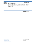
1.3
1-5
< 1. Specification >
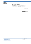
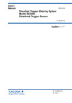
External Dimensions
("-B", "-N": Fork terminal)
("-E": Pin terminal)
GE RE SE G
("-G", "-F": Ring terminal)
15 13 14 16
General purpose KCl reserve tank
(with mounting bracket)
(OR8EFG---TT1-*A)
Cable gland is not included.
Reuse existing gland, or
replace.
Tube length: L
103
Approx.
115
Approx.
75
Model and codes
OR8EFG - - 03 - TT - *A
OR8EFG - - 05 - TT - *A
OR8EFG - - 07 - TT - *A
OR8EFG - - 10 - TT - *A
OR8EFG - - 15 - TT - *A
OR8EFG - - 20 - TT - *A
Ø27.5
2-inch pipe
(O.D. : Ø60.5)
Ø63
Terminal No. and colors
GE
15 (Red)
RE
13 (Brown)
SE
14 (Black)
16 (Green)
G
Cable length: L
64
Unit: mm
15 13 14 16
L
Approx. 3000
Approx. 5000
Approx. 7000
Approx. 10000
Approx. 15000
Approx. 20000
Approx.
45
Weight (kg)
Approx. 0.4
Approx. 0.6
Approx. 0.7
Approx. 1.0
Approx. 1.4
Approx. 1.9
Medium pressure KCl reserve tank
(with mounting bracket)
(OR8EFG---TT2-*A)
Ø38
Pressure gauge
60
Socket type connector
Rc1/4 screw
Coupling
with valve
Ø60.5
263
308
88
2-inch pipe
(O.D. : Ø60.5)
F1.1.ai
Figure 1.1
OR8EFG Filling type ORP Sensor
IM 12C07J01-01E
5th Edition : Nov.10,2015-00
Blank Page
2-1
< 2. Installation >
2.Installation
2.1
Preparation for Installation
2.1.1
Unpacking and Inspection
The Model OR8EFG ORP Sensor is well packed so as to prevent damage during shipment.
After removing the sensor from its shipping container, visually check the sensor for damage.
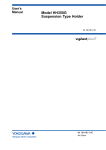
NOTE
1. When delivered, the "indicator electrode" and the "liquid junction" are packed separate from
the sensor body.
2. So that the "liquid junction" does not dry out do not take unpack its at this time.
OR8EFG - PT- 03 -TT1-E*A
MODEL
No.
Made in Japan
F2.1.ai
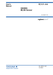
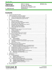
Figure 2.1
An Example of Model Number Entering to Nameplate
Sensor Body
Grounding Electrode
Indicator Electrode
Liquid Junction
Figure 2.2
2.1.2
F2.2.ai
Names of OR8EFG ORP Sensor Components
Mounting Indicator Electrode
Mount the indicator electrode on the sensor body as per the following procedure:
(1) Peel off the seal covering to the electrode mounting hole on the sensor body.
(2) Take the indicator electrode out of its bag and check to confirm that there is no dirt or
scratches on the O-ring that might affect the seal.
(3) Mount the indicator electrode in the sensor body. Insert the electrode in the electrode
mounting hole and screw the electrode clockwise until the O-ring fits tightly in the hole.
NOTE
Be careful not to allow water droplets to flow into the electrode mounting hole. If water gets into
the hole, wipe it dry, or insulation resistance may be affected.
IM 12C07J01-01E
5th Edition : Nov.10,2015-00
2.1.3
2-2
< 2. Installation >
Mounting Liquid Junction
The liquid junction is mounted in the sensor body when the KCl solution is poured into the sensor
body. Refer to Section 2.2.
2.1.4
Installing Holder
Usually, the ORP Sensor is suspended in a guide pipe or installed in a flow-through or
submersion holder. First install the holder.
2.1.5
Installing Associated Instruments
Make sure that the associated instrument (a ORP transmitter/converter or a junction terminal
box) to which the ORP Sensor cable is connected has already been installed.
2.2
Requirements for mounting the ORP Sensor
2.2.1
In case of installing the PH8HG Guide-pipe Holder
To install the sensor in the guide pipe, proceed as follows:
(1) Connect the sensor cable to the associated instrument correctly by referring to Section 2.3
provided later.
(2) Mount the liquid junction in the sensor body. Peel off the seal attached to the liquid junction
mounting hole in the sensor body. Screw the liquid junction gently two or three turns into the
hole.
(3) If specified, a reserve tank containing 250 mL KCl solution and mounting hardware to
hold this tank are supplied with the OR8EFG ORP Sensor. Attach the holding hardware to
the pipe (2-inch). Connect the reserve tank to the KCl solution supply tube of the sensor.
Remove the cap from the tank and screw the tube connector securely into the tank.
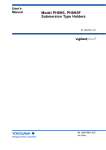
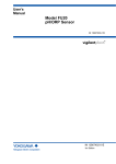
(4) Supply KCl solution to the sensor (see Figure 2.3). First, mount the reserve tank on the
mounting hardware with the tube connection part directed downwards. Using the pin
supplied with the tank, make several holes it its top (see Figure 2.3). Stand the sensor
upside down at a lower position than the reserve tank as shown in Figure 2.3 so that KCl
solution flows from the tank into the sensor. When the KCl solution fills the sensor and
overflows from the liquid junction mounting hole, securely screw the liquid junction into the
mounting hole.
Leave air space in the tank.
(Make several holes using the
pin supplied with the tank)
Liquid Junction (Loose)
General Purpose
Reserve Tank
Sensor Body
KCl Solution Tube
F2.3.ai
Figure 2.3
Supplying KCl Solution to Sensor Body
IM 12C07J01-01E
5th Edition : Nov.10,2015-00
< 2. Installation >
2-3
(5) Attach the "stopper" supplied with the guide pipe to the sensor cable.
Fix the sensor cable so that the sensor tip projects 20 to 30 mm out from the pipe end when
the ORP Sensor is suspended in the guide pipe as shown in Figure 2.4.
NOTE
If the sensor tip does not project out from the pipe end, the measured value may not respond
promptly to the ORP variations of the measured solution. This may cause problems for ORP
measurement and control. On the other hand, if the sensor tip projects too far from the pipe end,
the force on the sensor may damage the sensor cable from scraping it against the pipe.
Sensor Cable
Cable Clamp
Attaching "Stopper"
Sensor Cable
Stopper
2-inch (60.5 mm O.D)
Mounting Pipe
Arm Pipe
Guide Pipe
20 to 30 mm
ORP Sensor
Figure 2.4
Mounting Sensor in Guide Pipe
IM 12C07J01-01E
5th Edition : Nov.10,2015-00
2.2.2
2-4
< 2. Installation >
Installing Sensor in PH8HS Submersion Holder
To install the sensor in the submersion holder, proceed as follows:
(1) Pass the sensor cable through the sensor holder. If the submersion holder remains installed,
remove the sensor holder in any case.
For a pipe-mounting submersion holder without a cleaner, loosen the sensor holder nut to
remove the holder.
Right-angled Pipe Clamp
Nut
Arm Pipe
Sensor Holder
Removal of Sensor Holder (Arm Pipe used with option /MS1 or /MS2)
Bracket
Sensor Holder
Sensor Holder Nut
F2.5.ai
Removal of Sensor Holder (Stainless Bracket used with option /MS3 or /MS4)
Figure 2.5
Removal of Sensor Holder (for Pipe Mounting Sensor without Cleaner)
For a flange mounting submersion holder without a cleaner, remove the sensor holder by
loosening the two bolts securing the sensor holder to the flange (see Figure 2.6).
Fixing Bolt
Flange
F2.6.ai
Figure 2.6
Removal of Sensor Holder (for Flange Mounting Sensor without Cleaners)
IM 12C07J01-01E
5th Edition : Nov.10,2015-00
< 2. Installation >
2-5
Clamp (Screw)
Cleaner Holder
Sensor Holder
Figure 2.7
F2.7.ai
Removal of Sensor Holder (with Cleaner)
To install the sensor cable in the sensor holder, first remove the protector screwed onto the
sensor holder end and then remove the protective foam piece (for shipping; thus, it is not
necessary after the sensor is installed in the holder). Pass the sensor cable through the
O-ring then attach the O-ring to the sensor flange (see Figure 2.7).
When passing the sensor cable through the holder, if the inside of the holder is dirty or wet,
take special care to keep the cable dry by covering the sensor cable end with a polyethylene
bag or the like.
For details to install the sensor onto a holder, refer to relevant IMs.
Waterproof Cap Cover
Waterproof Cap
Pull out the sensor cable
and KCl solution supply tube.
Sensor Holder Pipe
Sensor Cable
KCl solution supply tube
Insert the sensor and cable
and KCl solution supply tube.
Sponge
(Remove)
O-ring
Flange
Sensor Body
Protector
Figure 2.8
Installing the Sensor Cable
IM 12C07J01-01E
5th Edition : Nov.10,2015-00
< 2. Installation >
2-6
(2) Connect the sensor cable to the associated instrument correctly by referring to Section 2.3.
(3) Mount the liquid junction in the sensor body. Peel off the seal attached to the liquid junction
mounting hole on the sensor body. Screw the liquid junction gently two or three turns into the
hole.
(4) If specified, a reserve tank containing 250 mL KCl solution and mounting hardware to hold
this tank are supplied with the OR8EFG ORP Sensor. Attach the mounting hardware to
the pipe (2-inch). Connect the reserve tank to the KCl solution supply tube of the sensor.
Remove the cap from the tank and screw the tube connector securely into the tank.
(5) Supply KCl solution to the sensor. First, mount the reserve tank on the mounting hardware
with the tube connection part directed downwards. Using the pin supplied with the tank
make several holes in its top (see Figure 2.3). Stand the sensor upside down at a position
lower than the reserve tank as shown in Figure 2.3 so that KCl solution flows from the tank
into the sensor. When the KCl solution fills the sensor and overflows from the liquid junction
mounting hole, securely screw the liquid junction into the mounting hole.
(6) Screw the protector to fix the sensor to the holder. In this case, remove the protective cap
and secure the protector so that the flange of the sensor compresses the O-ring firmly.
about the installation method.
ORP Sensor
O-ring
Protector
F2.9.ai
Figure 2.9
Installing Sensor in Submersion Holder
(7) Close the waterproof cap, and attach the holder to the arm pipe, flange or cleaner holder
completely.
IM 12C07J01-01E
5th Edition : Nov.10,2015-00
2.2.3
< 2. Installation >
2-7
Installing Sensor in Flow-through Holder
To install the sensor in a flow-through holder, proceed as follows:
(1) Connect the sensor cable to the associated instrument. First, remove the sensor fixing nut
and pass the sensor cable through the nut.
ORP Sensor
Sensor Fixing Nut
Figure 2.10
Preparation for Sensor Cable Connection
Properly connect the sensor cable by referring to Section 2.3.
(2) Mount the liquid junction on the sensor body. Peel off the seal covering the liquid junction
mounting hole in the sensor body. Screw the liquid junction softly into the hole by turning it
for two or three turns.
(3) If specified, a reserve tank containing 250 mL solution and mounting hardware to hold this
tank, or a medium pressure reserve tank are supplied with the OR8EFG ORP Sensor.
Attach the mounting hardware for general purpose reserve tank to a pipe (2-inch). Connect
the general purpose reserve tank to the KCl solution supply tube of the sensor. Remove the
cap from the tank and screw the tube connector securely into the tank.
When using a medium pressure reserve tank, attach it to a pipe (2-inch) and perform air
piping to supply pressure for reserve tank as shown in Figure 2.11. Connect the KCl supply
tube of the sensor to this reserve tank.
Maximum Measured Solution
Pressure +10 kPa
Pressure Gauge
Air Supply
Air Pressure
Regulator
To ORP Sensor
Figure 2.11
Air Piping for Pressurizing Medium Pressure Reserve Tank
(4) Supply KCl solution to the sensor.
IM 12C07J01-01E
5th Edition : Nov.10,2015-00
< 2. Installation >
2-8
l When a general purpose reserve tank is used.
First, mount the reserve tank on the holding hardware with the tube connection part directed
downwards. Using the pin supplied with the tank, make several holes in its top (see Figure 2.3).
Stand the sensor upside down at a position lower than the reserve tank as shown in Figure 2.3
so that KCl solution flows from the tank into the sensor. When the KCl solution fills the sensor
and overflows from the liquid junction mounting hole, securely screw the liquid junction into the
mounting hole.
l When a reserve tank for medium pressure is used.
First, fill the reserve tank with KCl solution (*1). Loosen the nut on the reserve tank upside and
remove the cap — the pressure gauge is mounted — and pour about 250 mL or KCl solution into
the tank. Stand the sensor upside down at a position lower than the reserve tank so that solution
flows from the tank into the sensor. When the KCl solution fills the sensor and overflows from the
liquid junction mounting hole, securely screw the liquid junction into the mounting hole. Remount
the cap of the reserve tank. Tighten the nut securely.
*1:
Use 3.3 mol/L KCl solution. If KCl powder (ordered separately) are supplied with the PH8AX accessories, dissolve one bag (60 g)
of KCl powder in pure water to make exactly 250 mL of solution.
(5) Connect the ORP Sensor to its holder. Remove the protective cap from the sensor. Also remove
the protective foam piece (for shipping - this is not necessary after installing the sensor) from the
holder. Be sure that the liquid junction and indicator electrode are mounted properly. Insert the
sensor tip into the holder and tighten the sensor fixing nut securely (see Figure 2.10).
ORP Sensor
Fixing Nut
O-ring
Flow-through Holder
2-inch Mounting Pipe
F2.12.ai
Figure 2.12
Installing Sensor in Flow-through Holder
IM 12C07J01-01E
5th Edition : Nov.10,2015-00
2.3
2-9
< 2. Installation >
ORP Sensor Cable Wiring Procedure
2.3.1
Processing of Cable Inlet Hole
Open the cable inlet hole in terminal box using the supplied punch tool. The location of the cable
inlet hole is shown by the circle-shaped groove under the case. The end of the supplied punch
tool is put in the center of this circle and it is tapped with appropriate force. You can punch out the
hole along the groove.
Hole punching tool for wiring
(supplied as accessory)
F2.13.ai
Figure 2.13
2.3.2
How to punch out the wiring hole
Connecting Sensor Cable
(1) Loosen two screws which are at front of terminal box and detach the cover.
(2) After detaching the nut from the cable gland of sensor cable, pull the cable into the terminal
box from sensor cable inlet hole.
(3) Connect the sensor cable to the terminals.
SENSOR
After passing the cable through the nut, check the symbol on each core wire, then connect
each core wire to the corresponding terminal.
CONVERTER
F2.14.ai
Figure 2.14
Connecting Sensor Cable (In case of the OR8TBG)
(4) Mount the cable gland in the cable inlet hole.
IM 12C07J01-01E
5th Edition : Nov.10,2015-00
2-10
< 2. Installation >
Put the nut in place, and screw it onto the main body sufficiently. At this time, loosen the cap
so that the cable is not twisted. After fixing the main body, tighten the cap to keep moisture
out of the equipment. However if the cap is screwed up too tight, the cable will be damaged.
Attach the nut in the
direction shown here
(so that it engages
the detent groove).
Nut
Gasket
Main unit
Cap
Figure 2.15
F2.15.ai
Cable Gland
(5) After completing the cable connections, replace the box cover securely, thus preventing
moisture from getting into the case.
2.3.3
Connecting Sensor Cable to Two-wire ORP Transmitter
To connect the sensor cable to the two-wire ORP Transmitter, proceed as follows:
(1) Loosen the four screws that tighten the transmitter cover. Then remove the transmitter
cover.
(2) Connect the sensor cables to the relevant terminals of the transmitter:
First, remove the nut from the cable gland. Insert the cable into the right opening for the
wiring. Then pass the cable through the nut, Connect the individual cable conductors to the
relevant terminals correctly by referring to the markings on the individual conductors.
For details, refer to relevant IMs.
Sensor cable
Figure 2.16
Connecting Sensor Cable to Two-wire ORP Transmitter
(3) Install the cable gland in the wiring hole as follows:
Pass the tip of the cable gland into the opening and completely tighten the gland with the nut inside the case.
After tightening the gland, secure the cap properly to prevent moisture from getting into the case.
Caution: Do not overly tighten the cap. Otherwise, the cable may be damaged.
(4) After completing the cable connections, replace the transmitter cover securely, thus
preventing moisture from getting into the case.
IM 12C07J01-01E
5th Edition : Nov.10,2015-00
2.3.4
2-11
< 2. Installation >
Connecting Sensor Cable to Four-wire ORP Converter
To connect the sensor cable to a Four-wire ORP Converter, proceed as follows:
(1) Loosen the four screws that tighten the converter cover. Then open the converter cover.
(2) Connect the sensor cables to the relevant terminals of the converter:
First, remove the nut from the cable gland. Insert the cable into the right opening for the
wiring. Then pass the cable through the nut, Connect the individual cable conductors to the
relevant terminals correctly by referring to the markings on the individual conductors.
For details, refer to relevant IMs.
Wiring Terminal
Board
Cable Inlet
Figure 2.17
Connecting Sensor Cable to Four-wire ORP Converter
(3) Install the cable gland in the wiring hole as follows:
Pass the tip of the cable gland into the opening and completely tighten the gland with the nut
inside the case.
After tightening the gland, secure the cap properly to prevent moisture from getting into the
case.
Caution: Do not overly tighten the cap. Otherwise, the cable may be damaged.
(4) After completing the cable connections, close the converter cover securely, thus preventing
moisture from getting into the case.
IM 12C07J01-01E
5th Edition : Nov.10,2015-00
Blank Page
3-1
< 3. Maintenance on operation >
3.
Maintenance on operation
3.1
Operation and Periodic Maintenance
3.1.1
Calibrating ORP Sensor Using Checking Solutions
Dirt attached to the liquid junction or sensitive parts (platinum electrodes) may have an adverse
effect on electromotive force and response characteristics, so ORP sensors require periodic
cleaning for good operating conditions. ORP sensors should be checked and calibrated if the
following conditions are met.
(1) Sensor checks
• If a new ORP sensor is used or the existing sensor has been unused for an extended period
of time.
• When an ORP sensor sensitive part (platinum electrode) or a liquid junction is cleaned.
(2)Calibration
• If sensor electromotive force is outside the allowable ranges.
• If the measured value by the ORP sensor is adjusted to the measured value by other
sensors.
For more detailed information on the calibration procedures, see the separate Instruction
Manuals "Two-wire Liquid Analyzer" (publication no. IM 12A01A02-01E) and "Four-wire pH/ORP
Converter" (publication no. IM 12B07C05-01E).
3.1.2
Pressurizing Reserve Tank
When the ORP Sensor with medium pressure reserve tank is used, apply air pressure to the
reserve tank before flowing the measured solution through the holder.
Set the air pressure a little higher than the maximum pressure of the measured solution during
the operation.
The flow rate of the KCl solution from the liquid junction is 3 mL/day or less when the pressure
difference between air and measured solution is 10 kPa and the flow rate increases in proportion
to the pressure difference. Therefore, it is important to minimize the consumption of the KCl
solution by minimizing the pressure variation of the measured solution and making sure that the
air pressure is not set too high.
IM 12C07J01-01E
5th Edition : Nov.10,2015-00
3.1.3
< 3. Maintenance on operation >
3-2
Replenishment of KCl Solution
When the KCl solution in the tank seems to be nearly exhausted while using a ORP Sensor with
general type reserve tank, replace the reserve tank with new one (provided separately as spare part).
Instead of tank replacement, when a KCl solution prepared using KCl powder is used for
replenishment, use 3.3 mol/L solution by dissolving 246 g of KCl powder in pure water to make
exactly one liter of solution. When pouring the solution into the tank, be careful that KCl solution
does not overflow from the vent holes of the tank.
When a ORP Sensor with a medium pressure reserve tank is used, replenish the KCl solution
when the KCl solution in the tank seems to be nearly exhausted. Carry out replenishment of KCl
solution as follows:
(1) Close the valves to shut off the (low of measured solution (see Figure 3.1) - first in the inlet
then the outlet valves in the flow-through type holder.
Outlet side
Stop Valve
Inlet side
Stop Valve
Figure 3.1
F3.1.ai
Process Piping of Flow-through Type Holder.
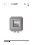
(2) Remove the socket connector on the reserve tank and stop the air pressurizing the tank (see Figure 3.2).
Socket type Connector
Press this part,
connector can be removed.
F3.2.ai
Figure 3.2
Socket Type Connector.
(3) Remove the nut fixing the reserve tank cap and remove the cap.
(4) Refill the tank with 3.3 mol/L KCl solution (see Figure 3.3).
The maximum solution level 30 to 40 mm lower than the top.
30 to 40 mm
F3.3.ai
Figure 3.3
Maximum KCl Replenishment Level
(5) Retighten the nut to fix the cap in position.
(6) Open the valve and let the measured solution flow through the holder.
IM 12C07J01-01E
5th Edition : Nov.10,2015-00
3.1.4
3-3
< 3. Maintenance on operation >
Cleaning Indicator Electrode and Liquid Junction
Staining of a indicator electrode or liquid junction can cause measurement errors. Therefore, if he
measured solutions tend to stain the electrode, the indicator electrode and liquid junction must
be cleaned periodically - depending on the degree of staining. if the ORP Sensor is installed in a
holder with a cleaner, the sensor is continuously (for an ultrasonic cleaner) or intermittently (for a
jet or brush cleaner) cleaned automatically.
Because of this, sensor cleaning is not usually required. However, if the sensor characteristics
are affected by chemical staining, for example, when the sensor is used for ORP measurement
of a highly alkaline solution, carry out acid washing.
To clean the indicator electrode or liquid junction, proceed as follows:
● Stains due to suspended Solids, Sticky Materials, Microbes or the like
Using soft tissue paper, wipe the stains off the indicator electrode or liquid junction. In
addition, clean off remaining stains by rinsing with water.
●
Stains due to Oily Materials
Wash off stains by submerging in a neutral detergent solution in a beaker, etc, (for from
several tens of minutes to several hours depending on the degree of staining).
●
Chemical Stains such as due to Metallic Adsorption
Place the indicator electrode or liquid junction in a diluted hydrochloric acid solution (1 to
2%) for several minutes (acid washing).
IM 12C07J01-01E
5th Edition : Nov.10,2015-00
3.2
< 3. Maintenance on operation >
3-4
Replacing Consumable Parts
3.2.1
Replacing Liquid Junction
Even after washing the liquid junction, if normal measurement cannot be made, replace the liquid
junction.
When replacing the liquid junction, fill the sensor with KCl solution to just before the solution
overflows through the liquid junction mounting hole. Use a 3.3 mol KCl solution (a higher
concentration of KCl or KCl powder) for this application.
1. When the liquid junction
is to be removed.
2. When the liquid junction
is to be installed.
F3.4.ai
Figure 3.4
3.2.2
Replacing Liquid Junction
Replacing O-rings for Indicator Electrode
As the inside of the indicator electrode mounting hole must have high insulation resistance,
fluorocarbon rubber O-rings - with superior chemical and heat resistance - are used for sealing.
Except for special uses, this O-ring does not need individual replacement. If any damage - which
might cause problems - is detected in the O-ring, as a rule, replace it along with the indicator
electrode. Although the O-ring can be replaced individually if the O-ring deteriorates much
faster than the indicator electrode, it is recommended that the whole indicator electrode be
replaced to avoid possible deterioration of the O-ring inside the indicator electrode. For individual
replacement of the O-ring, use the one recommended by Yokogawa.
When installing the O-ring, wind a slip of paper or tape around the thread part on the indicator
electrode so as not to scratch the O-ring. Otherwise, such scratches may damage its sealing
properties.
For ordering, refer to the Customer Maintenance Parts List (CMPL) at the end of the book to
check the appropriate part number of the O-ring.
O-ring (Ø9/Ø12)
O-ring (Ø6/Ø9)
Screw
Before installing, wind a slip of paper or tape
around the thread part to prevent scratches.
Figure 3.5
Installing the O-ring
IM 12C07J01-01E
5th Edition : Nov.10,2015-00
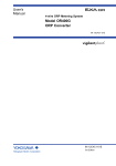
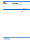
Customer
Maintenance
Parts List
Model OR8EFG
KCl Filling type ORP Sensor
Name Plate
4
Fork type
3
12
2
Pin type
13
1
Ring type
5
8 (9 through 11)
6
11
10
9
9 10
11
9
7
8 (9 through 11)
Item
1
2
3
Part No.
Below
—
K9142EJ
Below
K9142PF
K9142PG
K9142NH
K9142NJ
K9142NK
K9142NL
(L9901MB)
K9142PJ
K9142PK
K9142NM
K9142NN
K9142NP
K9142NQ
(L9901CA)
Qty
1
1
1
Description
Body Assembly
see GS 12B07B02(E)
Cap
KCl Filling Tube
Length 3 m
Length 5 m
Length 7 m
Length 10 m
Length 15 m
Length 20 m
For
general
use
8 (9 through 11)
Item
4
5
6
7
8
9
10
11
Part No.
L9813UG
K9084KQ
K9084KV
K9084CG
K9142VE
—
—
—
Qty
3 or 5
1
1
1
1
3
3
1
12
Below
K9142TS
K9142TT
1
K9142QR
K9142QS
1
1
Below
K9142TH
K9142UH
1
Junction Assembly
for general use
for OR8EFG/CJ ceramic junction
K9142QR
1
O-Ring, 6 mm ID. X 9 mm OD.
(Length by meter, max.100 m)
Length 3 m
Length 5 m
Length 7 m
Length 10 m
Length 15 m
Length 20 m
For
medium
pressure
(Length by meter, max.100 m)
10
13
Description
Clamp
Bottle (for general use)
Connector Assembly (for general use)
Nut
Holder Assembly
B.H. Screw, M4X18
Nut
Bracket
ORP Electrode Assembly
Pt
Au
O-Ring, 6 mm ID. X 9 mm OD.
O-Ring, 9 mm ID. X 12 mm OD.
All Rights Reserved, Copyright © 1984, Yokogawa Electric Corporation.
Subject to change without notice.
CMPL 12C03J01-01E
8th Edition : Mar. 2015 (YK)
2
Medium Pressure Type
2
3
1
4
Label
7
5
8
1
6
To KCl Filling Tube
Item
1
2
3
4
5
6
7
8
CMPL 12C03J01-01E
Part No.
K9142VG
L9835DD
L9867BS
G9303AE
K9142VP
Qty
1
1
1
1
1
K9142EJ
1
L9826AL
1
D0117XL-A 1
Description
Tank Assembly (item 2 through 8)
Joint
Pressure Gauge (Range:0 to 700 kPa)
O-Ring
Bracket
Cap
Bracket
U-Bolt Assembly
8th Edition : Mar. 2015 (YK)
i
Revision Information
Title
: Model OR8EFG KCl Filling type ORP Sensor
Manual No. : IM 12C07J01-01E
Oct. 2015/5th Edition
Added FLXA202
P i, P1-3.
Unification ot the material name
P1-1, P1-2.
CMPL 12C03J01-01E revised to 8th edition
Jun. 2013/4th Edition
P 1-4, Some revision of consumables; P 3-1, Some revision of pressurizing reserve tank; etc.
Sep. 2011/3rd Edition Page layout changed by InDesign
P.i, Reference manual number of FLXA21 added; P.v, Some of contents corrected; P.1-3, M4 ring
terminals for FLXA21 added to MS-code; P.1-5, M4 ring terminals added to external dimensions; P.2-13, Section no. corrected (2.3.3--->2.3.4);
CMPL 12C03J01-01E revised to 7th edition (P/N of KCl tube modified).
Apr. 2008/2nd Edition
M3 ring terminals added for PH450G, CMPL12C03J01-01E revised to 5th edition.
Sep. 2006/1st Edition
Newly published.
n If you want to have more information about Yokogawa products, you can visit
Yokogawa’s home page at the following web site.
Home page: http://www.yokogawa.com/an
IM 12C07J01-01E
5th Edition : Nov.10,2015-00
Blank Page