1
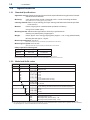
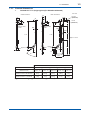
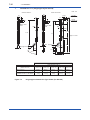
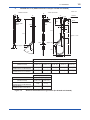
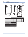
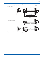
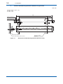
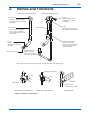
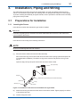
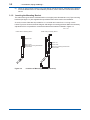
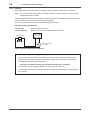
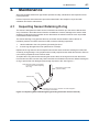
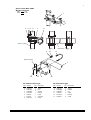
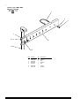
User’s Manual DOX8HS Submersion Type Holder IM 19H1D2-01E R IM 19H1D2-01E 4th Edition Blank Page i <INTRODUCTION> INTRODUCTION The DOX8HS submersion type holder is used to hold a sensor. This holder will keep the sensor immersed in the solution at all times for continuous measurement regardless of major changes in the level of the solution to be measured. The use of a submersion type holder with a jet washing device enables automatic cleaning of the front end of the sensor at desired intervals by a water jet or air jet without the need to remove the sensor. To fully exploit the capabilities of this product, read through the user's manual before use. Throughout this instruction manual important items with respect to handling are indicated by a Warning or Caution designation, depending upon the relative degree of importance. For safety reasons and to prevent the possibility of damaging the product, users should strictly observe these items. 1. Verifying specifications The DOX8HS submersion type holder is made either of polypropylene or stainless steel. The holder comes in different lengths and with or without a jet washing device. Upon taking receipt of the product, unpack it carefully, checking that no damage has occurred during transport. Check the parts list at the end of this manual to ensure that the received product is exactly what was ordered and that no parts are missing. Note: The DOX8HS submersion type holder is comprised of a style A (for the DO sigma series) and a style B (for EXA DO series and the EXAss series). Note that some of the parts for the two styles are not compatible. Whole assemblies can be used for both styles. EXA DO, EXAss series: style B (sensor installation: 45° tilt) DO sigma series: style A sensor installation: vertical) 2. Cautions This instruction manual describes installation procedures, inspection, maintenance and other handling procedures of the DOX8HS submersion type holder (style B). For detailed information on sensor handling, refer to the user's manual of each sensor. User's manuals for rerated equipment are listed below. Other related items are described in the following manuals. Model Title IM No. DO402G Dissolved oxygen converter IM 12J05D02-01E DO30G Dissolved oxygen sensor IM 12J5B3-01E DO70G Optical dissolved oxygen sensor IM 12J05D04-01E SS400G MLSS converter IM 12E6B1-02E SS300G MLSS sensor IM 12E6C1-01E SS350G Wiper-Washing controller IM 12E6E1-01E Media No. IM 19H1D2-01E 4th Edition : Dec. 2012 (YK) All Rights Reserved Copyright © 1998, Yokogawa Electric Corporation IM 19H1D2-01E ii <INTRODUCTION> For the safe use of this equipment Safety, Protection, and Modification of the Product • In order to protect the system controlled by the product and the product itself and ensure safe operation, observe the safety precautions described in this user’s manual. We assume no liability for safety if users fail to observe these instructions when operating the product. • If this instrument is used in a manner not specified in this user’s manual, the protection provided by this instrument may be impaired. • Be sure to use the spare parts approved by Yokogawa Electric Corporation (hereafter simply referred to as YOKOGAWA) when replacing parts or consumables. • Modification of the product is strictly prohibited. • The following symbols are used in the product and user’s manual to indicate that there are precautions for safety: Notes on Handling User’s Manuals • Please hand over the user’s manuals to your end users so that they can keep the user’s manuals on hand for convenient reference. • Please read the information thoroughly before using the product. • The purpose of these user’s manuals is not to warrant that the product is well suited to any particular purpose but rather to describe the functional details of the product. • No part of the user’s manuals may be transferred or reproduced without prior written consent from YOKOGAWA. • YOKOGAWA reserves the right to make improvements in the user’s manuals and product at any time, without notice or obligation. • If you have any questions, or you find mistakes or omissions in the user’s manuals, please contact our sales representative or your local distributor. Warning and Disclaimer The product is provided on an “as is” basis. YOKOGAWA shall have neither liability nor responsibility to any person or entity with respect to any direct or indirect loss or damage arising from using the product or any defect of the product that YOKOGAWA can not predict in advance. IM 19H1D2-01E iii <INTRODUCTION> Symbol Marks Throughout this user’s manual, you will find several different types of symbols are used to identify different sections of text. This section describes these icons. WARNING Indicates a potentially hazardous situation which, if not avoided, could result in death or serious injury. CAUTION Indicates a potentially hazardous situation which, if not avoided, may result in minor or moderate injury. It may also be used to alert against unsafe practices. IMPORTANT Indicates that operating the hardware or software in this manner may damage it or lead to system failure. NOTE Draws attention to information essential for understanding the operation and features. Tip This symbol gives information that complements the current topic. SEE ALSO This symbol identifies a source to be referred to. IM 19H1D2-01E iv <INTRODUCTION> After-sales Warranty Do not modify the product. During the warranty period, for repair under warranty consult the local sales representative or service office. Yokogawa will replace or repair any damaged parts. Before consulting for repair under warranty, provide us with the model name and serial number and a description of the problem. Any diagrams or data explaining the problem would also be appreciated. If we replace the product with a new one, we won’t provide you with a repair report. Yokogawa warrants the product for the period stated in the pre-purchase quotation Yokogawa shall conduct defined warranty service based on its standard. When the customer site is located outside of the service area, a fee for dispatching the maintenance engineer will be charged to the customer. In the following cases, customer will be charged repair fee regardless of war- ranty period. • Failure of components which are out of scope of warranty stated in instruction manual. • Failure caused by usage of software, hardware or auxiliary equipment, which Yokogawa Electric did not supply. • Failure due to improper or insufficient maintenance by user. • Failure due to modification, misuse or outside-of-specifications operation which Yokogawa does not authorize. • Failure due to power supply (voltage, frequency) being outside specifications or abnormal. • Failure caused by any usage out of scope of recommended usage. • Any damage from fire, earthquake, storms and floods, lightning, disturbances, riots, warfare, radiation and other natural changes. Yokogawa does not warrant conformance with the specific application at the user site. Yokogawa will not bear direct/indirect responsibility for damage due to a specific application. Yokogawa Electric will not bear responsibility when the user configures the product into systems or resells the product. Maintenance service and supplying repair parts will be covered for five years after the production ends. For repair for this product, please contact the nearest sales office described in this instruction manual. IM 19H1D2-01E v <CONTENTS> DOX8HS Submersion Type Holder IM 19H1D2-01E 4th Edition CONTENTS INTRODUCTION ...................................................................................................i For the safe use of this equipment ...................................................................ii After-sales Warranty ..........................................................................................iv 1. Overview.................................................................................................... 1-1 1.1 Features of the DOX8HS Submersion Type Holder ...................................... 1-1 1.2 Specifications.................................................................................................... 1-2 1.2.1 Standard Specifications ..................................................................... 1-2 1.2.2 Model and Suffix codes...................................................................... 1-2 1.2.3 External Dimensions .......................................................................... 1-3 2. Names and Functions .............................................................................. 2-1 3. Installation, Piping and Wiring ................................................................ 3-1 3.1 3.2 3.3 4. Preparations for lnstallation ............................................................................ 3-1 3.1.1 Inserting the Sensor ........................................................................... 3-1 3.1.2 Inserting the Mounting Bracket .......................................................... 3-2 Installation ......................................................................................................... 3-3 3.2.1 Selecting Measurement Point............................................................ 3-3 3.2.2 Selecting a Place of Installation for the DOX8HS Submersion Type Holder ........................................................................................................... 3-3 3.2.3 Securing DOX8HS Submersion Type Holder.................................... 3-3 3.2.4 Installing DOX8HS Submersion Type Holder .................................... 3-3 Piping and Wiring (for cleaning)...................................................................... 3-4 3.3.1 Items to Note with Regard to Piping Work ......................................... 3-4 3.3.2 Piping Examples ................................................................................ 3-5 3.3.3 Wiring ................................................................................................. 3-6 Maintenance.............................................................................................. 4-1 4.1 Inspecting Sensor Retaining O-ring ............................................................... 4-1 4.2 Inspecting the Cleaning Device....................................................................... 4-2 4.2.1 Inspecting Jet Washing Device.......................................................... 4-2 4.2.2 Inspecting Solenoid Valve.................................................................. 4-2 Customer Maintenance Parts List ......................................CMPL 19H01D02-01E Revision Information ...............................................................................................i IM 19H1D2-01E Blank Page 1-1 < 1. Overview > 1. Overview 1.1 Features of the DOX8HS Submersion Type Holder • Holds the sensor in place without being affected by the conditions of the solution to be measured The sensor is steadily held at the measurement point no matter how fast the solution flows. The material of the holder can be selected to suit the temperature of the solution to be measured or corrosive substances it contains. Only the front end of the sensor is exposed to the solution to minimize the likelihood of problems. • Sensor is held at a tilt angle of 45° to allow stable measurements Measurement results are less likely to be affected by air bubbles enabling noise free measurements in a wide range of processes. • Sensor front end is automatically cleaned at regular intervals at the place at installation Water jet or air jet cleaning substantially reduces dirt at the front end of the sensor. This makes it possible to reduce the frequency of maintenance even in highly contaminated solutions. Sensor Jet washing device Figure 1.1 Washing utility pipe Washing utility pipe Sensor cable Sensor cable Optical dissolved oxygen sensor Jet washing device Sensor in DOX8HS Submersion Type Holder (with washing device) IM 19H1D2-01E 1-2 < 1. Overview > 1.2 Specifications 1.2.1 Standard Specifications Applicable sensors: Dissolved Oxygen Sensor DO30G, Optical Dissolved Oxygen Sensor DO70G and MLSS Sensor SS300G Mounting: 2-inch pipe mounting vertical or horizontal, with 1 or 2 set of mounting hardware. (Note) Make sure the mounting pipe is firmly installed. Cleaning method: Water or air jet cleaning (The wiper cleaning of MLSS meter should be specified on the sensor.) Material: Holder; Polypropylene or stainless steel equivalent to SUS316) O-ring; Fluoro-rubber (Viton) Mounting bracket: Stainless steel (equivalent to SUS316) or galvanized iron Cleaning unit (wetted parts); Polypropylene Weight: Holder; Approx. 0.5 to 3.6 kg (polypropylene), Approx. 1.5 to 11.5 kg (stainless steel) Mounting bracket; Approx. 1 kg/set Measuring temperature: 0 to 80 °C (Note) The temperature may be limited by the specifications of the sensor. Measuring flow speed: 2 m/s or less. (Note) The flow rate may be limited by the specifications of the sensor. Utility required for cleaning unit: Utility Pressure (kPa) Flow rate Water jet 100 to 200 5 to 20 l/min Air jet 100 to 200 10 to 20 Nl/min (Note 1) Pressure and flow rate must be simultaneously satisfied at the holder inlet port. (Note 2) A large braid-reinforced tube of Ø22 x Ø15 is recommended for supply due to the flow rate. 1.2.2 Model and Suffix codes Model Suffix Code Option Code DOX8HS Material Submersion type holder Polypropylene Stainless steel -PP -S3 Pipe Length -10 -15 -20 -25 -30 -35 -40 Style Description 1.0 m 1.5 m 2.0 m 2.5 m 3.0 m 3.5 m (stainless steel -S3 only) 4.0 m (stainless steel -S3 only) -C -L For DO30G and SS300G For DO70G Cleaning System(*1) -NN -JT None For jet cleaning (The solenoid valve must be specified separately) Connector for Cleaning -NN -JP -NP Style Code *B None Rc 1/2 1/2 NPT Style B Options Mounting Bracket (*2) /MS1 /MS2 /MS5 /MS6 Mounting bracket : 1 set Mounting bracket : 2 sets Mounting bracket (stainless steel) : 1 set Mounting bracket (stainless steel) : 2 sets *1: When using the wiper cleaning of MLSS meter, choose a proper cleaning system under the MS code of the MLSS sensor. *2: The required number of mounting bracket sets depends on the installation location and flow rate. In general, one set is sufficient for pipe lengths of 1 meter, and otherwise two sets are required. IM 19H1D2-01E 1-3 < 1. Overview > 1.2.3 External Dimensions 1. DOX8HS-PP--C (Polypropylene)(For DO30G and SS300G) Unit: mm <With Jet cleaner> <Without cleaner> 83 83 62 42 42 44 64 44 64 Sensor cable outlet Rc1/2 (Code: JP) 134 103 Sensor cable outlet Ø34 1/2 NPT (Code: NP) 35 48 62 Ø34 Ø22 L-323 L+47 L-26 Approx. L+245 Ø50 Approx. 50 Ø50 Approx. 50 75 45° 75 418 147 45° 205 Weight (Approx.) Nominal Holder Length (L) Specification of Holder (Model and Code) 1000 mm [ Code: -10 ] 1500 mm [ Code: -15 ] Without Cleaner DOX8HS-PP- -C-NN-NN*B/ Approx. 0.5 kg Approx. 0.65 kg With Jet cleaner DOX8HS-PP- -C-JT- P*B/ Approx. 1.6 kg Approx. 2.1 kg Figure 1.2 2500 mm [ Code: -25 ] 3000 mm [ Code: -30 ] Approx. 0.8 kg Approx. 0.95 kg Approx. 1.1 kg Approx. 2.6 kg Approx. 3.1 kg Approx. 3.6 kg 2000 mm [ Code: -20 ] Polypropylene Submersion Type Holder (For DO30G and SS300G) IM 19H1D2-01E 1-4 < 1. Overview > 1.DOX8HS-PP-¨¨-L (Polypropylene)(For DO70G) <Without cleaner> 83 83 62 42 42 44 64 Rc1/2 (Code: JP) 134 103 Sensor cable outlet Ø34 1/2 NPT (Code: NP) 35 48 62 44 64 Sensor cable outlet UNIT: mm <With Jet cleaner> Ø34 Ø22 L-323 L+72 L-1 Approx. L+281 Ø50 Approx. 63 Ø50 Approx. 63 102 45°C 75 454 147 45°C 239 Weight (Approx.) Nominal Holder Length (L) Specification of Holder (Model and Code) 1000 mm [ Code: -10 ] 1500 mm [ Code: -15 ] Without Cleaner DOX8HS-PP--L-NN-NN*B/ Approx. 0.5 kg Approx. 0.65 kg With Jet cleaner DOX8HS-PP--L-JT-P*B/ Approx. 1.7 kg Approx. 2.2 kg 2500 mm [ Code: -25 ] 3000 mm [ Code: -30 ] Approx. 0.8 kg Approx. 0.95 kg Approx. 1.1 kg Approx. 2.7 kg Approx. 3.2 kg Approx. 3.7 kg 2000 mm [ Code: -20 ] F19-1.EPS Figure 1.3 IM 19H1D2-01E Polypropylene Submersion Type Holder (For DO70G) 1-5 < 1. Overview > 2.DOX8HS-S3-¨¨-C (SUS316: Stainless steel)(For DO30G and SS300G) <Without cleaner> 83 83 62 42 UNIT: mm <With Jet cleaner> 42 62 1/2 NPT (Code: NP) 27 48 44 64 44 64 179 Sensor cable outlet Sensor cable outlet Ø34 Rc1/2 (Code: JP) 136 Ø34 Ø22 L-12 L-323 L-12 Approx. L+310 Approx. 62 Ø49 Ø49 45° Approx. 62 68 75 481 262 45° 203 Weight (Approx.) Nominal Holder Length (L) 1000 mm [ Code: 10 ] 1500 mm [ Code: 15 ] 2000 mm [ Code: 20 ] 2500 mm [ Code: 25 ] 3000 mm [ Code: 30 ] Without Cleaner DOX8HS-S3--C-NN-NN*B/ 1.9 kg 3.1 kg 4.3 kg 5.5 kg 6.7 kg With Jet cleaner DOX8HS-S3--C-JT-P*B/ 4.1 kg 5.6 kg 7.1 kg 8.6 kg 10.1 kg Specification of Holder (Model and Code) Weight (Approx.) Nominal Holder Length (L) Specification of Holder (Model and Code) Without Cleaner DOX8HS-S3--C-NN-NN*B/ With Jet cleaner DOX8HS-S3-C-JT-P*B/ Figure 1.4 3500 mm [ Code: -35 ] 4000 mm [ Code: -40 ] 7.9 kg 9.1 kg 11.6 kg 13.1 kg Stainless Steel Submersion Type Holder (For DO30G and SS300G) IM 19H1D2-01E 1-6 < 1. Overview > 2.DOX8HS-S3-¨¨-L (SUS316: Stainless steel)(For DO70G) UNIT: mm <Without cleaner> <With Jet cleaner> 83 83 62 42 42 62 1/2 NPT (Code: NP) 27 48 44 64 44 64 179 Sensor cable outlet 136 Sensor cable outlet Ø34 Rc1/2 (Code: JP) Ø34 Ø22 L+6 L-323 L+6 Approx. L+328 Approx. 71 Ø49 Ø49 45°C 75 Approx. 71 85 499 253 45°C 231 Weight (Approx.) Nominal Holder Length (L) 1000 mm [ Code:-10 ] 1500 mm [ Code:-15 ] 2000 mm [ Code:-20 ] 2500 mm [ Code:-25 ] 3000 mm [ Code:-30 ] Without Cleaner DOX8HS-S3--L-NN-NN*B/ 2.0 kg 3.2 kg 4.4 kg 5.6 kg 6.8 kg With Jet cleaner DOX8HS-S3--L-JT-P*B/ 4.2 kg 5.7 kg 7.2 kg 8.7 kg 10.2 kg Specification of Holder (Model and Code) Weight (Approx.) Nominal Holder Length (L) Specification of Holder (Model and Code) 3500 mm [ Code:-35 ] 4000 mm [ Code:-40 ] Without Cleaner DOX8HS-S3--L-NN-NN*B/ 8.0 kg 9.2 kg With Jet cleaner DOX8HS-S3--L-JT-P*B/ 11.7 kg 13.2 kg Figure 1.5 IM 19H1D2-01E Stainless Steel Submersion Type Holder (For DO70G) F20-1.EPS 1-7 < 1. Overview > 3. Mounting Bracket for Submersion Type Holder Mounting Hardware (Weight : Approx. 1kg) / MS1 - 1 set / MS2 - 2 sets <For Holder without cleaner> Unit: mm 68 64 2-inch (O.D. Ø60.5) Stanchion 94 90 54 Max : 515 Min : 110 Sensor Holder 600 Max : 515 Min : 110 <For Holder with Cleaner> Ø48.6 95 62 600 Cleaner Holder 2-inch (O.D. Ø60.5) Stanchion 90 130 54 100 Figure 1.6 Submersion Holder Mounting Bracket IM 19H1D2-01E 1-8 < 1. Overview > 4. Stainless Steel Mounting Bracket for Submersion Type Holder Unit: mm Stainless (Weight : Approx. 1 kg) / MS5 - 1 set / MS6 - 2 sets 600 182.5 to 440 (pitch : 51.5) (When with cleaner) 100 (When without cleaner) 51 44 28 49 86 Cleaner holder Sensor holder (When without cleaner) Figure 1.7 IM 19H1D2-01E 2-inch (O.D. Ø60.5) Stanchion Submersion Holder Mounting Bracket (Stainless steel) 2-1 < 2. Names and Functions > 2. Names and Functions Holder with washing device Holder without washing device Adapter Pipe for washing utility; supplied when 1/2 NPT is specified. Drip-proof cap Leads the cable downwards and prevents rain from entering the bolder. Clamp Secures the sensor holder to the washing device holder. (Sensor holder) Sensor holder Since the sensor is installed at a 45° angle. Air bubbles do not adhere to the front end of the sensor. Washing device holder Holds the jet washing device to provide a washing utility. Two hooks support the sensor holder. O-ring Prevents the solution to be measured from entering the holder. Sensor securing nut Jet washing device Cleans the sensor Front end by spraying it with an air or water jet Note: The figure shows a polypropylene holder. The stainless steel model differs slightly. Washing device holder Pipe Pipe Bracket Sensor holder Sensor holder Washing device holder Holder without washing device Holder with washing device Stainless steel Figure 2.1 Names and Functions IM 19H1D2-01E Blank Page 3-1 < 3. Installation, Piping and Wiring > 3. Installation, Piping and Wiring The submersion type holder comes in two configurations: one with a jet washing device and one without. The submersion type holder with washing device is equipped with utility (air or water) piping. To perform cleaning automatically at regular intervals, wires to operate the solenoid valve in the utility piping have to be provided. 3.1 3.1.1 Preparations for lnstallation Inserting the Sensor Insert the sensor when the submersion type holder is installed. SEE ALSO Information regarding sensor orientation and other details differ with the sensor used. Refer to the user’s manual of the sensor. Insert the sensor according to the following instructions. NOTE Be sure not to damage the front end of sensor. (1) Route the sensor cable to the sensor holder assembly. Remove the securing nut from the holder front end. Remove the sponge (used in transport and not needed after installation). Thread the O-ring over the sensor and place the O-ring on the sensor. Open the drip-proof cap and pull out the other end of the sensor cable. Drip-proof cap Sensor cable Sponge Submersion type holder (sensor holder assembly) (Remove) O-ring Securing nut Sensor Figure 3.1 Installation of the Sensor to the Submersion Type Holder (2) Attach the securing nut and secure the sensor to the sensor holder. Tighten properly so that the O-ring will act as a seal. (3) Close the drip-proof case. IM 19H1D2-01E 3-2 < 3. Installation, Piping and Wiring > (4) 3.1.2 When an optional wiper cleaning unit is specified for the MLSS sensor, install the wiper cleaning unit to the MLSS sensor. For the installation procedure, refer to the user's manual of the MLSS sensor. Inserting the Mounting Bracket The submersion type holder is used attached to 2-inch pipe (outer diameter 60.5 mm). Pipe mounting brackets (see figure 1.4) are supplied when specified and should be used in the installation. As a rule, one set of brackets is provided for a 1.0 m holder and 2 sets for a 1.5 m long or more holder. Figure 3.2 shows a schematic diagram indicating the mounting positions. Make the necessary adjustments if it is not possible to mount the brackets at the locations indicated in Figure 3.2. Unit : mm Holder without washing device Holder with jet washing device Approx. 250 Approx. 70 950 or more When two mounting bracket sets are provided. Figure 3.2 IM 19H1D2-01E 950 or more When two mounting bracket sets are provided. Locations of Mounting Brackets (reference) 3-3 < 3. Installation, Piping and Wiring > 3.2 3.2.1 Installation Selecting Measurement Point Install the DOX8HS submersion type holder so that the DO70G sensor and MLSS sensor, dissolved oxygen sensor, is located at the measurement point. Under normal conditions, select a measurement point that satisfies the following requirements. • A location where a typical measured value of the solution to be measured can be obtained Avoid locations where the solution to be measured is unevenly distributed since it will lead to hunting for a measured value. Also avoid locations where air bubbles are generated. • A location where the temperature and flow rate of the measured solution matches the usage conditions of the sensor and holder A fast flowing solution that contains sand may damage the sensor front end (membrane, prism or sensor cap).. 3.2.2 Selecting a Place of Installation for the DOX8HS Submersion Type Holder Sensors must be calibrated and maintained regularly. Thus the DOX8HS submersion type holder should be installed in a location that satisfies the following conditions. • Space enough to allow calibration and maintenance near the measurement point • A location where washing utility requirements are met. (submersion type holder with washing device.) CAUTION Installation Location of Holders (Guide Pipe, Submersion Type, etc) The holder should be used in a place that is as vibration free as possible. Using the holder in a place where it is affected by vibration, may result in damage to the holder. 3.2.3 Securing DOX8HS Submersion Type Holder The DOX8HS submersion type holder is normally secured to 2-inch pipe (outer diameter 60.5 mm) using a mounting bracket. The pipe shall be placed vertically. The submersion type holder must be removed to allow calibration and maintenance. Therefore install the holder in a location where removal is easy to perform. 3.2.4 Installing DOX8HS Submersion Type Holder (1) Secure the submersion type holder with the installed sensor (see section 3.1) to a stanchion (pipe for mounting the holder). NOTE Be sure not to soil or expose the prepared end of the sensor cable during the work When the submersion type holder has been secured, check that, • The sensor front end is in a location where it is not likely to collect air bubbles. • The sensor front end is immersed in the solution regardless of fluctuations in the solution level. (2) Connect the sensor cable to the converter (or terminal box). For details, refer to supplied user’s manual. IM 19H1D2-01E 3-4 < 3. Installation, Piping and Wiring > 3.3 Piping and Wiring (for cleaning) The following information concerns only the submersion type holder with jet washing device. For wiring when an optional wiper cleaning unit is specified for the MLSS sensor, refer to the user's manual of the SS350G Controller for Wiper Cleaning. 3.3.1 Items to Note with Regard to Piping Work Piping is provided to the submersion type holder with jet washing device to supply the air or water used for washing. Exercise care with the regard to the following during the piping work. • Washing device maintenance should be easy to perform. Use a soft hose (net-impregnated soft polyvinyl chloride resin tube) for the piping around the submersion type holder. To be on the safe side, make sure that there is enough hose to allow far errors. • In winter, provide heat insulation if there is a possibility the washing water will freeze. Washing is performed at designated intervals (any time cycle can be set using the converter). • Use a pipe with a diameter sufficient to provide the necessary pressure and flow rate. Use 15 A nominal diameter size for air pipes. The solenoid valve in the washing pipe line should be 15 A aperture (pipe joint port) that operates normal close (that closes when electrified). Yokogawa provides solenoid valves with the following specifications. [Model PH8MV Solenoid Valve] Pilot kick operated, 2-port valve. Open when energized. Fluid: Normal tap water, industrial water, or air Operating pressure: 0 to 1 MPa Forward (reverse) pressure resistance: 2 MPa Fluid temperature: Water; 5 to 60°C, Air; -10 to 60°C Cv: 4.5 Process connection: Rc 1/2 Power supply: 100/110/200/220 V AC, 50/60 Hz Construction: IP53 Material: Body; Bronze Sealing; Nitrile rubber Ambient temperature: Maximum 50°C Cable inlet connection: G 1/2 Weight: IM 19H1D2-01E Approx. 0.9 kg < 3. Installation, Piping and Wiring > 3.3.2 3-5 Piping Examples (1) Air Jet Washing Contact signal (from converter) Power supply Pressure regulator Air supply Solenoid Pressure: 2 MPa or less valve JIS 15 A hard pipe JIS 16 A net-impregnated soft polyvinyl chloride resin tube Note: Adjust the secondary pressure of the pressure regulator to between 100 and 200 kPa. Figure 3.3 Example Showing Air Jet Cleaning (2) Water (industrial water) Jet Washing Contact signal (from converter) Power supply Ball valve Solenoid valve Industrial water Pressure: 100 to 200 kPa JIS 15 A hard pipe 16 A net-impregnated soft polyvinyl chloride resin tube Figure 3.4 Example Showing Water (industrial water) Jet Washing (3) Water (tap water) Jet Washing Contact signal (from converter) Power supply JIS 16 A net-impregnated soft polyvinyl chloride resin tube Tap water (pressure 100 to 200 kPa) Float valve Stop valve Tank Pump Note: When the PH8PU1 pump/tank is used, refer to IM 19C1E1-01E for maintenance. Figure 3.5 Example Showing Water (tap water) Jet Washing IM 19H1D2-01E 3-6 3.3.3 < 3. Installation, Piping and Wiring > Wiring Normally, washing is executed when a "cleaning" contact signal is received from the converter. Note: The contact output must be set to "cleaning" function. For details, refer to the user’s manual supplied with each converter. Install wiring so that when the contact signal is output drive power is supplied to the solenoid valve (or pump), and utility (air or water flows into the washing device). The cleaning contact of the converter has the following specifications. Cleaning contact specifications Contact type: Relay contact (dry contact) Contact capacity: Refer to user’s manual supplied with the converter. Solenoid Valve Washing contact Signal Terminals Solenoid valve driving power supply Figure 3.6 Solenoid Driving Circuit Wiring Output timing of "cleaning" contact signal • The converter is first turned on, then cleaning is executed after the preset cleaning interval elapses. If the automatic cleaning function is set to "stop", when "execute" is set cleaning is executed after the cleaning interval lapses. Execution of manual cleaning and "automatic cleaning start" command IM 19H1D2-01E • The converter can be manually operated any time through key operation. • The automatic cleaning start command can be sent any time by inputting the contact signal to the converter. 4-1 < 4. Maintenance > 4. Maintenance When the DOX8HS submersion type holder operates normally, maintenance and inspections need not be performed. Perform inspection and maintenance procedures described in this chapter in conjunction with calibration and sensor maintenance. 4.1 Inspecting Sensor Retaining O-ring The sensor is designed such that it can be immersed in the solution up to the sensor cable and the entry of solution in the holder does not lead to a breakdown. However, damage to the sensor cable sheathing could lead to poor insulation and for that reason the solution should as much as possible not be allowed inside the holder. The sensor retaining O-ring prevents the entry of solution into the holder to reduce the risk of insulation problems. If solution enters the holder, make the following inspections. 1. Has dirt adhered to the O-ring reducing its sealing function? 2. ls the O-ring damaged from wear (deformed or cracked)? Replace the O-ring when the above inspection shows that cause of solution entering the holder was caused by O-ring damage. O-ring replacement normally requires sensor cable disconnection. Be sure not to soil the prepared end of the sensor cable. To replace the O-ring without disconnecting the sensor cable, the O-ring has to be from the sensor front end and across the sensor body. Remove all dirt accumulated on the sensor. Before inserting the O-ring to prevent that it is damaged (rust) through exposure to dirt. See Figure 4.1. Note: Remove all drift accumulated on the sensor before replacing the O-ring. Submersion type holder (sensor holder) O-ring Sensor body Sensor securing nut Turn the O-ring to move it. Position it so that elongation in the flange is minimized. Figure 4.1. Replacing Sensor Retaining Ring (inserting it from the sensor front end) IM 19H1D2-01E 4-2 < 4. Maintenance > 4.2 Inspecting the Cleaning Device The following information concerns only the submersion type holder with jet washing device. SEE ALSO For maintenance of the MLSS sensor with wiper-washing, refer to the MLSS sensor's mamual. Make the following inspections of the device. 1. Check the nozzle of the jet washing device for clogging. 2. With the solenoid valve closed, check whether or not the washing utility is discharged. If no error can be found in the device when it is installed, remove the submersion type holder and inspect again. 4.2.1 Inspecting Jet Washing Device When the nozzle is clogged, the cleaning effect of the jet washing device will decrease. Use a 0.8 mm thick metal needle or the like to unclog the nozzle. Remove the jet washing device from the holder to inspect the interior of the washing device. If excessively dirty with slurry or algae, clean thoroughly. Figure 4.2. Unclogging the Nozzle 4.2.2 Inspecting Solenoid Valve Check that the cleaning utility is not discharged from the jet washing device while the solenoid valve is closed. Replace the solenoid valve if the leak is more than a smal1 amount that does not affect measurement. IM 19H1D2-01E Customer Maintenance Parts List Model DOX8HS Submersion Type Holder Without Cleaner Type (-NN) With Cleaner Type (-JT) 1 1 2 6 2 7 3 3 4 8 4 10 9 5 5 Item Part No. Qty Description 1 2 3 4 5 K9144NB K9145NA — K9142QV — K9171NX K9171LX 1 1 1 1 1 6 — K9115RS L9832AT 1 Adapter (-NP: 1/2 NPT Female) (for DOX8HS-PP) (for DOX8HS-S3) 7 8 9 10 L9813WA — K9142QU K9143JN 1 1 1 1 Clamp Cleaner Holder (see Table 2) O-Ring Nozzle (for jet cleaner) Cap Nameplate Sensor Holder (see Table 1) O-Ring Nut (for DOX8HS-PP) (for DOX8HS-S3) All Rights Reserved, Copyright © 1997, Yokogawa Electric Corporation. Subject to charge without notice. CMPL 19H01D02-01E 1st Edition : Dec. 1997 (YK) 3rd Edition : Jan. 2012 (YK) 2 Table 1. Item 3 Sensor Holder Part Number Part Number Holder Length (L) Part Number For DOX8HS-PP-uu-C For DOX8HS-S3-uu-C For DOX8HS-PP-uu-L For DOX8HS-S3-uu-L Without Cleaner Type (-NN) With Cleaner Type (-JT) 1.0 m 1.5 m 2.0 m 2.5 m 3.0 m 3.5 m 4.0 m 1.0 m 1.5 m 2.0 m 2.5 m 3.0 m 3.5 m 4.0 m K9171NG K9171NH K9171NJ K9171NK K9171NL — — K9171NA K9171NB K9171NC K9171ND K9171NE — — K9679SK K9679SL K9679SM K9679SN K9679SP — — K9679SA K9679SB K9679SC K9679SD K9679SE — — K9171LG K9171LH K9171LJ K9171LL K9171LK K9171GS K9171GT K9171LA K9171LB K9171LC K9171LE K9171LD K9171GN K9171GP K9679QK K9679QL K9679QM K9679QN K9679QP K9679QQ K9679QR K9679QA K9679QB K9679QC K9679QD K9679QE K9679QF K9679QG Table 2. Item 8 Cleaner Holder Part Number Part Number Holder Length (L) Part Number For DOX8HS-PP-uu-C For DOX8HS-S3-uu-C For DOX8HS-PP-uu-L For DOX8HS-S3-uu-L 1.0 m 1.5 m 2.0 m 2.5 m 3.0 m 3.5 m 4.0 m K9171MA K9171MB K9171MC K9171MD K9171ME — — CMPL 19H01D02-01E K9171KA K9171KB K9171KC K9171KE K9171KD K9171KF K9171KG K9679RA K9679RB K9679RC K9679RD K9679RE — — K9679NA K9679NB K9679NC K9679ND K9679NE K9679NF K9679NG 3rd Edition : Jan. 2012 (YK) 3 Option Code:/MS1, /MS2 Mounting Bracket /MS1 /MS2 1 set 2 sets 1 2 3 4 5 6 7 8 (Sensor holder) 1 (Stanchion) 9 11 10 (Cleaner holder) 1 13 10 9 For without cleaner type 3rd Edition : Jan. 2012 (YK) 12 For with cleaner type Item Part No. Qty Description Item Part No. Qty 1 2 3 4 5 K9144AM L9813VP Y9801BU Y9800WU K9145LM 1 1 2 2 1 Pipe Clamp Nut Washer Bracket 1 2 9 10 11 K9144AM L9813VP Y9800WU Y9801BU L9800JC 1 1 8 8 2 Pipe Clamp Washer Nut U-Bolt 6 7 8 L9800JF K9145LL L9813VN 1 1 1 U-Bolt Supporter Clamp 12 13 K9144SA L9800JG 1 2 Bracket U-Bolt Description CMPL 19H01D02-01E 4 Option Code: /MS5, /MS6 Mounting Bracket /MS5 /MS6 1 set 2 sets 1 2 3 7 6, 2, 3 4 (Holder) 5, 2 CMPL 19H01D02-01E Item Part No. Qty 1 2 3 4 5 L9800JJ Y9800WU Y9801BU K9145LQ L9800PV 1 6 4 1 2 U-Bolt Washer Nut Bracket Nut 6 7 K9145LW K9145LR 1 1 U-Bolt Bracket Description 3rd Edition : Jan. 2012 (YK) i Revision Information Title Manual No. : DOX8HS Submersion Type Holder : IM 19H1D2-01E Dec. 2012/4th Edition Addition of DO70G Sensor, etc P.i, Introduction, “ 2. Contents” Table: Added of the DO70G optical dissolved oxygen sensor; P.1-1, Section 1.1, “ Features of the DOX8HS Submersion Type Holder” Figure 1.1: Added of the figure; P.1-2, Section 1.2.1, “ Standard Specifications” Applicable sensors: Added of the DO70G optical dissolved oxygen sensor. Section 1.2.2, “Model and Suffix codes” Added of the DO70G; P.1-3, Section 1.2.3, “ External Dimensions” Added of the model name (DO30G and SS300G); P.1-4, Section 1.2.3, “ External Dimensions” Added of the model name (DO70G); P.1-5, Section 1.2.3, “ External Dimensions” Added of the model name (DO30G and SS300G); P.1-6, Section 1.2.3, “ External Dimensions” Added of the model name (DO70G); P.3-3, Section 3.2.1, “ Selecting Measurement Point” Added of the description of the DO70G; P.3-4, Section 3.3.1, “ Items to Note with Regard to Piping Work” Style change of the PH8MV; Customer Maintenance Parts List CMPL 19H01D02-01E, revised to 3rd Edition, some of illustration changed. Aug. 2011/3rd Edition Page layout changed by InDesign P.1-2 Specifications are equalized to GS. Dec. 2006/2nd Edition Some error correction. Dec. 1998/1st Edition Newly published. If you want to have more information about Yokogawa products, you can visit Yokogawa’s home page at the following web site. Home page: http://www.yokogawa.com/an IM 19H1D2-01E Blank Page


![Model DO402G Dissolved Oxygen Converter [Style: S3]](http://vs1.manualzilla.com/store/data/005725233_1-bd7e4c5bf258da59a958f30153ff00ea-150x150.png)
![SS400G MLSS Converter [Style:S2.2]](http://vs1.manualzilla.com/store/data/005726371_1-b873ef07ceb169a0226d293b313a67fd-150x150.png)