1
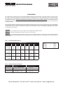
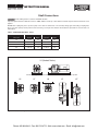
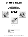
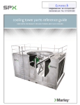
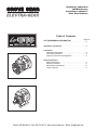
Installation, Lubrication
and Maintenance
Instructions LeCentric™
Inline Gear Reducers
Table of Contents
™
Page No.
CAUTION/WARNING INFORMATION
. . . . . . . . . . . . . . . . . . . . . . . . . . . . . . . . . . . . . . . . . . . 2
Installation Instructions . . . . . . . . . . . . . . . . . . . . . . . . . . . 3
Lubrication
Lubrication Instructions . . . . . . . . . . . . . . . . . . . . . . . . . . 4
Lubrication Quantities . . . . . . . . . . . . . . . . . . . . . . . . . . . 4
Approved Lubricants and Suppliers . . . . . . . . . . . . . . . . 4
General Operation
Shaft Connections . . . . . . . . . . . . . . . . . . . . . . . . . . . . . .
Mounting Positions . . . . . . . . . . . . . . . . . . . . . . . . . . . . .
Maintenance Instructions . . . . . . . . . . . . . . . . . . . . . . . .
Class of Service . . . . . . . . . . . . . . . . . . . . . . . . . . . . . . .
Phone: 800.894.0412 - Fax: 888.723.4773 - Web: www.clrwtr.com - Email: [email protected]
5
5
6
6
INSTRUCTION MANUAL
™
IMPORTANT INFORMATION
Please Read Carefully
The following
and
information is supplied to you for your protection and
to provide you with many years of trouble free and safe operation of your Grove Gear product.
Read ALL instructions prior to operating reducer. Injury to personnel or reducer failure may be caused by
improper installation, maintenance or operation.
• Written authorization from Grove Gear is required to
operate or use reducers in man lift or people moving
devices.
• Check to make certain application does not exceed
the allowable load capacities published in the current
catalog.
• Buyer shall be solely responsible for determining the
adequacy of the product for any and all uses to which
Buyer shall apply the product. The application by Buyer
shall not be subject to any implied warranty of fitness for
a particular purpose.
• For safety, Buyer or User should provide protective guards
over all shaft extensions and any moving apparatus
mounted thereon. The User is responsible for checking all
applicable safety codes in his area and providing suitable
guards. Failure to do so may result in bodily injury and/or
damage to equipment.
• Hot oil and reducers can cause severe burns. Use extreme
care when removing lubrication plugs and vents.
• Make certain that the power supply is disconnected before
attempting to service or remove any components. Lock
out the power supply and tag it to prevent unexpected
application power.
• Reducers are not to be considered fail safe or self-locking
devices. If these features are required, a properly sized,
independent holding device should be utilized. Reducers
should not be used as a brake.
• Any brakes that are used in conjunction with a reducer
must be sized or positioned in such a way so as to not
subject the reducer to loads beyond the catalog rating.
• Lifting supports including eyebolts are to be used for
vertically lifting the gearbox only and no other associated
attachments or motors.
• Use of an oil with an EP additive on units with backstops
may prevent proper operation of the backstop. Injury to
personnel, damage to the reducer or other equipment may
result.
• Overhung loads subject shaft bearings and shafts to stress
which may cause premature bearing failure and or shaft
breakage from bending fatigue, if not sized properly.
• Test run unit to verify operation. If the unit tested is a
prototype, that unit must be of current production.
• If the speed reducer cannot be located in a clear and
dry area with access to adequate cooling air supply,
then precautions must be taken to avoid the ingestion of
contaminants such as water and the reduction in cooling
ability due to exterior contaminants.
• Mounting bolts should be routinely checked to ensure that
the unit is firmly anchored for proper operation.
IMPORTANT INFORMATION
In the event of the resale of any of the goods, in whatever form, Resellers/
Buyers will include the following language in a conspicuous place and in a
conspicuous manner in a written agreement covering such sale:
The manufacturer makes no warranties or representations,
express or implied, by operation of law or otherwise, as to
the merchantability or fitness for a particular purpose of the
goods sold hereunder. Buyer acknowledges that it alone has
determined that the goods purchased hereunder will suitably
meet the requirements of their intended use. In no event will
the manufacturer be liable for consequential, incidental or other
damages. Even if the repair or replacement remedy shall be
deemed to have failed of its essential purpose under Section
2-719 of the Uniform Commercial Code, the manufacturer shall
have no liability to Buyer for consequential damages.
Resellers/Buyers agree to also include this entire document including
the warnings and cautions above in a conspicuous place and in a
conspicuous manner in writing to instruct users on the safe usage
of the product.
This information should be read together with all other printed information
supplied by Grove Gear.
Phone: 800.894.0412 - Fax: 888.723.4773 - Web: www.clrwtr.com - Email: [email protected]
INSTRUCTION MANUAL
™
INSTRUCTIONS
General Operation
1. Run the motor which drives the reducer and check the direction of reducer output rotation. Consult motor nameplate for instructions to reverse the
direction of rotation.
2. Attaching the load: On direct coupled installations, check shaft and coupling alignment between speed reducer and loading mechanism. On chain/
sprocket and belt/pulley installation, locate the sprocket or pulley as close to the oil seal as possible to minimize overhung load. Check to verify that the
overhung load does not exceed specifications published in the catalog.
3. High momentum loads: If coasting to a stop is undesirable, a braking mechanism should be provided to the speed reducer output or the driven
mechanism.
T
he system of connected rotating parts must be free from critical speed, torsional or other type vibration, no matter how induced. The
responsibility for this system analysis lies with the purchaser of the speed reducer.
Installation Instructions
The following instructions apply to standard Grove Gear LeCentric™ type reducers with base or flange mounting in motorized and non-motorized double
and triple reduction options.
1. Mount the unit to a rigid flat surface using grade 5 or higher fasteners. The mounting fasteners should be the largest standard size that will fit in the base
mounting hole. Shim as required under flange or base feet which do not lie flat against the mounting surface.
2. LeCentric™ reducers are filled with proper amount of oil from Grove Gear. Oil quantity is based on mounting position, as indicated on reducer nameplate.
Unless otherwise indicated with order, all reducers are filled to level indicated for position H3. If position other than the one indicated on nameplate is
required, refer to Figure 1 for alternate mounting positions and Table 1 for oil quantities.
3. Connect motor to speed reducer.
4. LeCentric™ reducers are designed to operate without a vent. Installation of a vent is not required.
D
O NOT CHANGE MOUNTING POSITIONS WITHOUT CONTACTING FACTORY. Altering the mounting position may require special
lubrication provisions which must be factory installed.
D
o not operate the reducer without making sure it contains the correct amount of oil. Confirm that mounting position on nameplate matches
application requirement per Figure 1. Do not overfill or underfill with oil, or injury to personnel, reducer or other equipment may result.
A
unit cannot be used as an integral part of a machine superstructure which would impose additional loads on the unit other than those
imposed by the torque being transmitted either through a shaft-mounted arrangement, and any shaft mounted power transmitting device.
(e.g. sprockets, pulleys, couplings)
F
or safe operation and to maintain the unit warranty, when changing a factory installed fastener for any reason it becomes the responsibility
of the person making the change to properly account for fastener grade, thread engagement, load, tightening torque and the means of torque
retention.
Phone: 800.894.0412 - Fax: 888.723.4773 - Web: www.clrwtr.com - Email: [email protected]
INSTRUCTION MANUAL
™
Lubrication
ALL standard reducers ordered from Factory are filled with Mobil Glygoyle 460 Polyglycol (PAG) lubricant or equivanent suitable continuous duty option
with a -10°F to 120°F ambient temperature range. Lubrication quantities are specified in Table 1 for various mounting positions. Prior to startup, verify that
the mounting position on nameplate matches required position (see Fig. 1). LeCentric™ reducers are filled to proper amount of oil based on mounting
position printed on nameplate. All LeCentric™ Gear Reducers will be filled with oil for position “H3” unless otherwise specified. If the ambient temperature will
be outside the range for the lubricant installed at the factory, drain and refill the reducer with the proper viscosity lubricant prior to use. Consult the Factory
for alternate lubricants.
Change Intervals: LeCentric™ units utilize extreme pressure lubricants which protect the teeth in the event of the oil thinning out due to local temperature
rise, or high pressure due to accidental overloads. LeCentric™ reducers are “lubed-for-life” and do not require regular oil changes under normal industrial
operating conditions and environments if the reducers are operated in severe environments (i.e. high or low temperatures, high altitudes, dusty, caustic,
etc.) oil changes may be required. Do not mix different oils in the reducer. Oils should be compatible with Viton® seal material.
Oil should be changed/checked if reducer is used in severe environment.
In the Food and Drug Industry (including animal food), consult the lubricants which are acceptable to the Food and Drug Administration
and for other authorative bodies having jurisdiction. Factory supplied PAG oil is acceptable for incidental food contact (NSF H1) for use in and around food
processing areas.
Table 1 - Lubrication Quantities (ounces)
Mounting Positions
Series H3 H6 H7 H8 V5 V6
717 (2 Stage) 8.5 10.0 13.5 13.5 13.5 17.0
717 (3 Stage) 10.0
12.0 15.0 15.0 15.0 18.5
727 (2 Stage) 8.5
10.0 13.5 13.5 13.5 17.0
727 (3 Stage) 10.0 12.0 15.0 15.0 15.0 18.5
747 (2 Stage) 15.0 19.0 34.0 37.0 37.0 39.0
747 (3 Stage) 25.5 25.5 35.5 39.0 40.5 40.5
757 (2 Stage) 19.0 29.0 37.0 40.5 40.5 42.0
757 (3 Stage) 25.5 30.5 39.0 42.0 44.0 46.0
16 oz.
2 Pints
4 Quarts
1 Gallon
=
=
=
=
1 Pint
1 Quart
1 Gallon
128 oz.
Table 2 - Approved Lubricants and Suppliers
Manufacturer Lubricant Temperature Range (˚F)
Exxon Co. USA Spartan Synthetic EP 320 -25 to +113
Mobil Oil Corp. Mobilgear SHC 320 -25 to +113
Pennzoil Prod. Co. Super Maxol “S” 320 -25 to +113
Phone: 800.894.0412 - Fax: 888.723.4773 - Web: www.clrwtr.com - Email: [email protected]
INSTRUCTION MANUAL
™
Shaft Connections
provide suitable guards in accordance with OSHA standards.
Input and output shaft extension diameter tolerance is +0.000”; -0.001” for shafts up to 1.375” diameter. The fitted component must be machined to ensure
proper fit.
DO NOT drive coupling hub, pinion, sprocket or pulley on the shaft. An endwise blow on the shaft may damage gears and bearings. Coupling hubs,
pinions, sprockets or pulleys must be pushed onto the shaft using a screw jack device fitted into the threaded hole provided in the end of the shaft, see
Table 3 below.
Table 3 - Shaft End threaded Holes - Inches
Output Shaft Input Shaft
Drive Size Tap Size Depth Tap Size Depth
717 1/4-20 .62 1/4-20 .62
727 5/16-18 .75
1/4-20 .62
747 5/16-18 .75
5/16-18 .75
757
5/16-18 .75
5/16-18 .75
H3 (Standard Position)
Standard mounting position is H3. All reducers will be filled to this level, unless otherwise specified.
H6
H7
H8
V5
V6*
**Not Recommended
Figure 1 - Reducer Mounting Positions
Phone: 800.894.0412 - Fax: 888.723.4773 - Web: www.clrwtr.com - Email: [email protected]
INSTRUCTION MANUAL
™
Maintenance Instructions
Your Grove Gear reducer has been tested and adjusted at the factory. Dismantling or replacement of components must be done by Grove Gear to maintain
the warranty.
LeCentric™ reducers are lubed-for-life and do not require regularly scheduled oil changes/checks. However, if the reducer is used in a severe environment,
it is recommended that the oil is checked or changed every 6000 hrs. or after 2 years of operation. If the oil level is low, (refer to Figure 1 for mounting
positions) add proper lubrication through the filler plug.
If seal leakage has resulted in the loss of a significant amount of oil, it may be necessary to add more lubricant. For normal ambient temperature conditions,
Grove Gear recommends Mobil PAG 460 or equivalent oil for all LeCentric™ reducers.
Mounting bolts should be routinely checked to ensure that the unit is firmly anchored for proper operation.
Seal Replacement: The LeCentric™ line of speed reducers utilize premium quality seals which are the state-of-the-art in sealing technology. Seals are,
however, a wear item and eventually need to be replaced. Replacement can be easily accomplished by following the steps below:
1. Lock out and tag out the reducer’s power source.
2. Remove any load from the input and/or output shafts of the reducer prior to disconnecting any drive components.
3. Remove appropriate drive components to gain access to seal to be replaced.
4. Drain oil if seal is below oil level.
5. Remove the worn seal without damaging the shaft surface or the seal bore. This can be done by drilling a 0.062” diameter hole in the casing (being
careful not to drill into the bearing behind the seal). Screw a #10 sheet metal screw into the hole and pry out the seal.
6. Clean the seal bore in housing of sealant.
7. Before installing the new seal, use electrical tape to cover any keyways on the shaft to prevent seal lip damage.
8. Grease the seal lips with bearing grease and apply a sealant to the seal bore in housing.
9. Slide the seal onto the shaft being careful not to fold the inner lip over on any shaft steps.
10. Press the seal into its bore with a sleeve that presses on the seal casing, being careful to keep the seal square in its bore.
11. Refill reducer to proper level with appropriate lubricant.
Always check for proper oil level after filling. Do not overfill or underfill with oil, or injury to personnel, reducer or other equipment may result.
Do not mix different oils in the reducer.
12. Reconnect any drive components disconnected in Step 3. Make sure components are properly aligned.
Class of Service
All capacity ratings are based on proper application of American Gear Manufacturers Association (AGMA) service factors. Load conditions must be within
cataloged ratings published in the current Grove Gear Catalog (available upon request).
For information contact:
PRINTED IN U.S.A.
6777G/5K/8-10/TG/BH
Grove Gear and Electra-Gear are trademarks of Regal Beloit Corporation.
Phone: 800.894.0412 - Fax: 888.723.4773 - Web: www.clrwtr.com - Email: [email protected]