1
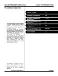
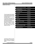
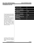
2004 IMPREZA SERVICE MANUAL
QUICK REFERENCE INDEX
ENGINE SECTION 1
This service manual has been prepared
to provide SUBARU service personnel
with the necessary information and data
for the correct maintenance and repair
of SUBARU vehicles.
This manual includes the procedures
for maintenance, disassembling, reassembling, inspection and adjustment of
components and diagnostics for guidance of experienced mechanics.
Please peruse and utilize this manual
fully to ensure complete repair work for
satisfying our customers by keeping
their vehicle in optimum condition.
When replacement of parts during
repair work is needed, be sure to use
SUBARU genuine parts.
All information, illustration and specifications contained in this manual are
based on the latest product information
available at the time of publication
approval.
FUJI HEAVY INDUSTRIES LTD.
FUEL INJECTION (FUEL SYSTEMS)
FU(H4SO)
EMISSION CONTROL
(AUX. EMISSION CONTROL DEVICES)
EC(H4SO)
INTAKE (INDUCTION)
IN(H4SO)
MECHANICAL
ME(H4SO)
EXHAUST
EX(H4SO)
COOLING
CO(H4SO)
LUBRICATION
LU(H4SO)
SPEED CONTROL SYSTEMS
SP(H4SO)
IGNITION
IG(H4SO)
STARTING/CHARGING SYSTEMS
SC(H4SO)
ENGINE (DIAGNOSTICS)
EN(H4SO)(diag)
FUEL INJECTION (FUEL SYSTEMS)
FU(H4SOw/oOBD)
EMISSION CONTROL
(AUX. EMISSION CONTROL DEVICES)
EC(H4SOw/oOBD)
INTAKE (INDUCTION)
IN(H4SOw/oOBD)
MECHANICAL
ME(H4SOw/oOBD)
EXHAUST
EX(H4SOw/oOBD)
COOLING
CO(H4SOw/oOBD)
G1870GE2
2004 IMPREZA SERVICE MANUAL
QUICK REFERENCE INDEX
ENGINE SECTION 1
LUBRICATION
LU(H4SOw/oOBD)
SPEED CONTROL SYSTEMS
SP(H4SOw/oOBD)
IGNITION
IG(H4SOw/oOBD)
STARTING/CHARGING SYSTEMS
SC(H4SOw/oOBD)
ENGINE (DIAGNOSTICS)
EN(H4SOw/oOBD)
(diag)
G1870GE2
STARTING/CHARGING SYSTEMS
SC(H4SO)
1.
2.
3.
4.
Page
General Description ....................................................................................2
Starter .........................................................................................................7
Generator ..................................................................................................13
Battery.......................................................................................................19
General Description
STARTING/CHARGING SYSTEMS
1. General Description
A: SPECIFICATIONS
1. NON-TURBO MODEL
Starter
Item
Type
Vehicle type
Model
Manufacturer
Voltage and output
Direction of rotation
Number of pinion teeth
Voltage
No-load characCurrent
teristics
Rotating speed
Voltage
Current
Load characteristics
Torque
Lock characteristics
Rotating speed
Voltage
Current
Torque
Type
Generator
Model
Manufacturer
Voltage and output
Polarity on ground side
Direction of rotation
Armature connection
Output current
Regulated voltage
Battery
Europe and
Type and capac- South America
ity
Others
Designation
Reduction type
MT
1.6 L AT
2.0 L AT, 2.5 L AT
M000T30471
M000T30571
M000T20171
Mitsubishi Electric
12 V — 1.0 kW
12 V — 1.4 kW
Counterclockwise (when observed from pinion)
8
9
11 V
95 A or less
90 A or less
2,500 rpm or more
2,000 rpm or more
7.5 V
7.7 V
300 A
400 A
8.84 N·m (0.90 kgf-m, 6.5 ft-lb) or
16.7 N·m (1.70 kgf-m, 12.3 ft-lb) or
more
more
870 rpm or more
710 rpm or more
4V
3.5 V
680 A or less
960 A or less
17 N·m (1.73 kgf-m, 12.5 ft-lb) or
31 N·m (3.16 kgf-m, 22.9 ft-lb) or
more
more
Rotating-field three-phase, voltage regulator built-in type, with load response
control system
A2TB5391, A2TB6291*
Mitsubishi Electric
12 V — 75 A
Negative
Clockwise (when observed from pulley side)
Three-phase Y-type
1,500 rpm — 30 A or more
2,500 rpm — 64 A or more
5,000 rpm — 76 A or more
14.1 — 14.8 V [20°C (68°F)]
1.6 L: 12 V — 48 AH (55D 23L)
12 V — 48 AH (55D 23L)
2.0 L: 12 V — 52 AH (65D 23L)
2.5 L: 12 V — 52 AH (75D 23L)
12 V — 27 AH (34D 19L)
*: For Australia and general
SC(H4SO)-2
General Description
STARTING/CHARGING SYSTEMS
2. TURBO MODEL
Starter
Item
Type
Vehicle type
Model
Manufacturer
Voltage and output
Direction of rotation
Number of pinion teeth
Voltage
No-load characCurrent
teristics
Rotating speed
Voltage
Current
Load characteristics
Torque
Lock characteristics
Rotating speed
Voltage
Current
Torque
Type
Generator
Model
Manufacturer
Voltage and output
Polarity on ground side
Direction of rotation
Armature connection
Output current
Regulated voltage
Battery
Europe and
Type and capac- South America
ity
Australia
Designation
Reduction type
MT
AT
228000 — 9270
M001T20171
DENSO
Mitsubishi Electric
12 V — 1.0 kW
12 V — 1.4 kW
Counterclockwise (when observed from pinion)
9
11.5 V
11 V
90 A or less
3,000 rpm or more
2,000 rpm or more
8V
7.7 V
280 A
400 A
16.7 N·m (1.70 kgf-m, 12.3 ft-lb) or
9.3 N·m (0.95 kgf-m, 6.9 ft-lb) or more
more
860 rpm or more
710 rpm or more
5V
3.5 V
515 A or less
960 A or less
16 N·m (1.63 kgf-m, 11.8 ft-lb) or
31 N·m (3.16 kgf-m, 22.9 ft-lb) or
more
more
Rotating-field three-phase, voltage regulator built-in type, with load response
control system
A2TB5391, A2TB6291*
Mitsubishi Electric
12 V — 75 A
Negative
Clockwise (when observed from pulley side)
Three-phase Y-type
1,500 rpm — 30 A or more
2,500 rpm — 64 A or more
5,000 rpm — 76 A or more
14.1 — 14.8 V [20°C (68°F)]
12 V — 48 AH (55D 23L)
12 V — 52 AH (65D 23L)
12 V— 40 AH (50D 20L)
*: For Australia and South America (except STi)
SC(H4SO)-3
General Description
STARTING/CHARGING SYSTEMS
B: COMPONENT
1. STARTER
• EXCEPT FOR DOHC TURBO MT MODEL
(1)
(4)
(10)
(9)
(3)
(2)
(8)
(7)
(6)
(5)
(16)
(12)
(11)
(14)
(15)
(13)
SC-02009
(1)
(2)
(3)
(4)
(5)
(6)
Front bracket
Sleeve bearing
Lever set
Magnet switch ASSY
Stopper set
Overrunning clutch
(7)
(8)
(9)
(10)
(11)
(12)
Internal gear ASSY
Shaft ASSY
Gear ASSY
Packing
Yoke ASSY
Armature
SC(H4SO)-4
(13)
(14)
(15)
(16)
Brush holder ASSY
Sleeve bearing
Rear cover
Rear cover set
General Description
STARTING/CHARGING SYSTEMS
• DOHC TURBO MT MODEL
(4)
(2)
(11)
(10)
(9)
(3)
(8)
(1)
(7)
(6)
(17)
(5)
(16)
(15)
(14)
(13)
(12)
SC-00168
(1)
(2)
(3)
(4)
(5)
(6)
Sleeve bearing
Front bracket
Lever set
Magnet switch ASSY
Stopper set
Overrunning clutch
(7)
(8)
(9)
(10)
(11)
(12)
Internal gear ASSY
Shaft ASSY
Gear ASSY
Ball
Packing
Yoke ASSY
SC(H4SO)-5
(13)
(14)
(15)
(16)
(17)
Armature
Brush holder ASSY
Brush
Sleeve bearing
Rear cover
General Description
STARTING/CHARGING SYSTEMS
2. GENERATOR
(5)
(6)
(4)
(2)
(3)
(1)
(12)
(11)
(10)
(9)
(8)
(7)
SC-00144
(1)
(2)
(3)
(4)
Pulley
Front cover
Ball bearing
Bearing retainer
(5)
(6)
(7)
(8)
Rotor
Bearing
Stator coil
IC regulator with brush
C: CAUTION
• Wear working clothing, including a cap, protective goggles and protective shoes during operation.
• Remove contamination including dirt and corrosion before removal, installation or disassembly.
• Keep the disassembled parts in order and protect them from dust or dirt.
• Before removal, installation or disassembly, be
sure to clarify the failure. Avoid unnecessary removal, installation, disassembly, and replacement.
(9)
(10)
(11)
(12)
Brush
Rectifier
Rear cover
Terminal
• Be careful not to burn your hands, because each
part on the vehicle is hot after running.
• Be sure to tighten fasteners including bolts and
nuts to the specified torque.
• Place shop jacks or rigid racks at the specified
points.
• Before disconnecting electrical connectors of
sensors or units, be sure to disconnect the ground
cable from battery.
SC(H4SO)-6
Starter
STARTING/CHARGING SYSTEMS
2. Starter
5) Disconnect the connector and terminal from
starter.
A: REMOVAL
1) Disconnect the ground cable from battery.
SC-00006
(A) Terminal
(B) Connector
FU-00009
2) Remove the air cleaner case. (Non-turbo model)
<Ref. to IN(H4SO)-5, REMOVAL, Air Cleaner
Case.>
3) Remove the intercooler. (Turbo model)
<Ref. to IN(H4DOTC)-10, REMOVAL, Intercooler.>
4) Remove the air cleaner case stay. (Non-turbo
model)
• MT MODEL
6) Remove the starter from transmission.
SC-00007
B: INSTALLATION
Install in the reverse order of removal.
Tightening torque:
50 N·m (5.1 kgf-m, 37 ft-lb)
SC-00004
• AT MODEL
SC-00007
C: DISASSEMBLY
SC-00005
1. STARTER ASSEMBLY
1) Loosen the nut which holds the terminal M of
switch assembly, and then disconnect the connector.
2) Remove the bolts which hold the switch assembly, and then remove switch assembly, plunger and
plunger spring from starter as a unit.
SC(H4SO)-7
Starter
STARTING/CHARGING SYSTEMS
NOTE:
Be careful because the pinion gap adjustment
washer may sometimes be used on the mounting
surface of switch assembly.
NOTE:
Before removal of the yoke, put alignment marks
on the yoke and front bracket.
(B)
(D)
(A)
(C)
SC-00171
(B)
(A)
SC-00169
(A)
(B)
(C)
(D)
(A) Switch ASSY
(B) Plunger
3) Remove both through-bolts and brush holder
screws, and then detach the rear cover and brush
holder.
(A)
Front bracket
Yoke
Ball
Armature
5) Remove packing A, planetary gears, packing B
and plate.
(B)
(B)
(A)
(C)
(D)
SC-00170
SC-00172
(A) Brush holder
(B) Rear cover
4) Remove the armature and yoke from front bracket. The ball used as a bearing will come off from the
armature end.
(A)
(B)
(C)
(D)
Packing A
Planetary gear
Plate
Packing B
6) Remove the shaft assembly and overrunning
clutch as a unit.
SC(H4SO)-8
Starter
STARTING/CHARGING SYSTEMS
NOTE:
Note the direction of the lever before removing.
(C)
2. BRUSH HOLDER
NOTE:
Only the brush holder of turbo MT model starter
can be disassembled.
Slightly open the metal fitting while holding the insulating plate against the brush holder. Remove
the insulating plate.
The brush and spring can be easily removed from
the brush holder at this time.
(A)
(B)
SC-00173
(B)
(A) Shaft ASSY
(B) Overrunning clutch
(C) Lever
(A)
7) Remove the overrunning clutch from shaft assembly as follows:
(1) Remove the stopper from ring by lightly tapping the stopper with an appropriate tool (such
as a fit socket wrench).
(2) Remove the ring, stopper and clutch from
shaft.
(C)
SC-00174
(A) Brush holder
(B) Insulating plate
(C) Metal fitting
D: ASSEMBLY
1) Assemble in the reverse order of disassembly.
2) Apply grease to the following parts before assembly.
• Front and rear bracket sleeve bearings
• Armature shaft gear
• Outer periphery of plunger
• Mating surfaces of plunger and lever
• Gear shaft splines
• Mating surfaces of lever and clutch
• Ball at armature shaft end
• Planetary gear
E: INSPECTION
1. ARMATURE
SC-00014
(A)
(B)
(C)
(D)
1) Check the commutator for any sign of burns of
rough surfaces or stepped wear. If wear is of a minor nature, correct it by using sand paper.
2) Run-out test
Check the commutator run-out, and then replace if
it exceeds the limit.
Socket wrench
Ring
Shaft
Stopper
SC(H4SO)-9
Starter
STARTING/CHARGING SYSTEMS
Commutator run-out:
Standard
0.05 mm (0.0020 in)
Service limit
Less than 0.10 mm (0.0039 in)
4) Armature short-circuit test
Check the armature for short-circuit by placing it on
a growler tester. Hold an iron sheet against the armature core while slowly rotating armature. A
short-circuited armature will cause the iron sheet to
vibrate and to be attracted to core. If the iron sheet
is attracted or vibrates, the armature, which is
short-circuited, must be replaced or repaired.
(A)
(B)
SC-00021
(A) Dial gauge
(B) V-block
SC-00023
3) Depth of segment mold
Check the depth of segment mold.
(A) Iron sheet
(B) Grower tester
Depth of segment mold:
0.5 mm (0.020 in)
5) Armature ground test
Using a circuit tester, touch one probe to the commutator segment and the other to shaft. There
should be no continuity. If there is continuity, the armature is grounded.
Replace the armature if it is grounded.
(B)
(C)
(A)
SC-00022
(A) Depth of mold
(B) Segment
(C) Mold
SC-00024
2. YOKE
Make sure the pole is set in position.
3. OVERRUNNING CLUTCH
Inspect the teeth of pinion for wear and damage.
Replace if it is damaged. It is normal if the pinion rotates smoothly in direction of rotation (counterclockwise) and does not rotate in the opposite
direction.
CAUTION:
Do not clean the overrunning clutch with oil to
prevent grease from flowing out.
SC(H4SO)-10
Starter
STARTING/CHARGING SYSTEMS
4. BRUSH AND BRUSH HOLDER
1) Brush length
Measure the brush length, and then replace if it is
worn down to under the service limit.
Replace if abnormal wear or cracks are noticed.
Terminal/Specified resistance:
S — M/Less than 1 Ω
S — Ground/Less than 1Ω
M — B/More than 1 MΩ
Brush length:
Standard
12.3 mm (0.484 in)
Service limit
7.0 mm (0.276 in)
B
S
M
SC-00075
6. SWITCH ASSEMBLY OPERATION
1) Connect the terminal S of switch assembly to
positive terminal of battery with a lead wire, and
starter body to ground terminal of battery. The pinion should be forced endwise on shaft.
(A)
(B)
SC-00102
(A) Service limit line
(B) Brush
2) Brush movement
Be sure the brush moves smoothly inside brush
holder.
3) Brush spring force
Measure the brush spring force with a spring scale.
If it is less than the service limit, replace the brush
holder.
Brush spring force:
CAUTION:
With the pinion forced endwise on shaft, the
starter motor may rotate because current flows
through the pull-in coil to motor, however, this
is not a problem.
2) Disconnect the connector from terminal M, and
then connect the positive terminal of battery and
terminal M using a lead wire and ground terminal to
starter body.
In this test set up, the pinion should return to its
original position even when it is pulled out with a
screwdriver.
Standard
Except DOHC turbo MT model
15.9 — 19.5 N (1.62 — 1.99 kgf, 3.57 — 4.38
lb) (when new)
DOHC turbo MT model
21.6 N (2.2 kgf, 4.9 lb) (when new)
Service limit
Except DOHC turbo MT model
2.5 N (0.25 kgf, 0.56 lb)
DOHC turbo MT model
5.9 N (0.6 kgf, 1.3 lb)
(B)
(A)
SC-00175
(A) Terminal S
(B) Terminal M
5. SWITCH ASSEMBLY
Using a circuit tester (set in “ohm”), check that
there is continuity between terminals S and M, and
between terminal S and ground.
Also check to be sure there is no continuity between terminals M and B.
SC(H4SO)-11
Starter
STARTING/CHARGING SYSTEMS
7. PERFORMANCE TEST
The starter should be submitted to performance
tests whenever it has been overhauled, to assure
its satisfactory performance when installed on the
engine.
Three performance tests, no-load test, load test,
and lock test, are presented here; however, if the
load test and lock test cannot be performed, carry
out at least the no-load test.
For these performance tests, use the circuit shown
in figure.
S
B
(B)
(A)
M
+
(C)
12V
V
A
SC-00077
(A) Variable resistor
(B) Magnetic switch
(C) Starter body
1) No-load test
With switch on, adjust the variable resistor to obtain
11 V, take the ammeter reading, and then measure
the starter speed. Compare these values with the
specifications.
No-load test (standards):
Voltage/Current
1.6L MT, 2.0L Non-turbo MT, 2.5L MT and 1.6L
AT
MAX. 11 V/95 A
2.0L Non-turbo AT, 2.5L AT
MAX. 11 V/90 A
2.0L Turbo
MAX. 11 V/90 A
Rotating speed
1.6L MT, 2.0L Non-turbo MT, 2.5L MT and 1.6L
AT
More than 2,500 rpm
2.0L Non-turbo AT, 2.5L AT
More than 2,000 rpm
2.0L Turbo MT
More than 3,000 rpm
2.0L Turbo AT
More than 2,000 rpm
2) Load test
Apply the specified braking torque to starter. The
condition is satisfactory if the current draw and
starter speed are within the specifications.
Load test (standards):
Voltage/Load
1.6L MT, 2.0L Non-turbo MT, 2.5L MT and 1.6L
AT
7.5 V/8.84 N·m (0.90 kgf-m, 6.5 ft-lb)
2.0L Non-turbo AT, 2.5L AT
7.7 V/16.7 N·m (1.70 kgf-m, 12.3 ft-lb)
2.0L Turbo MT
8 V/9.3 N·m (0.95 kgf-m, 6.9 ft-lb)
2.0L Turbo AT
7.7 V/16.7 N·m (1.70 kgf-m, 12.3 ft-lb)
Current/Speed
1.6L MT, 2.0L Non-turbo MT, 2.5L MT and 1.6L
AT
More than 300 A/870 rpm
2.0L Non-turbo AT, 2.5L AT
More than 400 A/710 rpm
2.0L Turbo MT
More than 280 A/860 rpm
2.0L Turbo AT
More than 400 A/710 rpm
3) Lock test
With the starter stalled, or not rotating, measure the
torque developed and current draw when the voltage is adjusted to the specified voltage.
Lock test (standards):
Voltage/Current
1.6L MT, 2.0L Non-turbo MT, 2.5L MT and 1.6L
AT
Less than 4 V/680 A
2.0L Non-turbo AT, 2.5L AT
Less than 3.5 V/960 A
2.0L Turbo MT
Less than 5 V/515 A
2.0L Turbo AT
Less than 3.5 V/960 A
Torque
1.6L MT, 2.0L Non-turbo MT, 2.5L MT and 1.6L
AT
17 N·m (1.73 kgf-m, 12.5 ft-lb)
2.0L Non-turbo AT, 2.5L AT
31 N·m (3.16 kgf-m, 22.9 ft-lb)
2.0L Turbo MT
16 N·m (1.63 kgf-m, 11.8 ft-lb)
2.0L Turbo AT
31 N·m (3.16 kgf-m, 22.9 ft-lb)
SC(H4SO)-12
Generator
STARTING/CHARGING SYSTEMS
3. Generator
5) Remove the bolts which install generator onto
bracket.
A: REMOVAL
1) Disconnect the ground cable from battery.
SC-00032
FU-00009
2) Disconnect the connector and terminal from
generator.
• NON-TURBO MODEL
B: INSTALLATION
Install in the reverse order of removal.
Tightening torque:
25 N·m (2.5 kgf-m, 18.1 ft-lb)
CAUTION:
Check and adjust the V-belt tension. <Ref. to
ME(H4SO)-44, INSPECTION, V-belt.> or <Ref. to
ME(H4DOTC)-55, INSPECTION, V-belt.>
SC-00029
• TURBO MODEL
SC-00032
C: DISASSEMBLY
1) Remove the four through-bolts.
SC-00143
3) Remove the V-belt cover.
4) Remove the front side V-belt.
<Ref. to ME(H4SO)-43, FRONT SIDE BELT, REMOVAL, V-belt.> or <Ref. to ME(H4DOTC)-54,
FRONT SIDE BELT, REMOVAL, V-belt.>
SC(H4SO)-13
SC-00078
Generator
STARTING/CHARGING SYSTEMS
2) Heat portion (A) of rear cover to 50°C (122°F)
with a heater drier.
(A)
CAUTION:
When holding the rotor with a vise, place aluminum plates or wooden pieces on the vise jaws
to prevent rotor from damage.
(A)
(B)
SC-00079
(C)
3) Then insert the tip of a flat tip screwdriver into the
gap between stator core and front cover. Pry them
apart to disassemble.
(D)
(A)
(B)
(C)
(D)
SC-00036
Front cover
Pulley
Nut
Rotor
5) Remove the ball bearing as follows.
(1) Remove the bolt, and then remove the bearing retainer.
(A)
(A)
SC-00080
(A) Screwdriver
4) Hold the rotor with a vise and remove pulley nut.
SC-00081
(2) Firmly install an appropriate tool (such as a
fit socket wrench) to bearing inner race.
SC-00035
SC-00082
(3) Push the ball bearing off the front cover using a press.
SC(H4SO)-14
Generator
STARTING/CHARGING SYSTEMS
6) Remove the bearing from rotor using a bearing
puller.
(2) Unsolder the connection between IC regulator and rectifier to remove the IC regulator.
SC-00046
7) Unsolder connection between rectifier and stator
coil to remove the stator coil.
SC-00085
9) Remove the brush as follows.
(1) Remove cover A.
CAUTION:
Do not allow a 180 — 270 W soldering iron to
contact the terminals for more than 5 seconds
at once because the rectifier cannot withstand
so much heat.
(A)
SC-00086
(A) Cover A
(2) Remove cover B.
SC-00083
(A)
8) Remove the IC regulator as follows.
(1) Remove the screws which secure IC regulator to rear cover.
SC-00087
(A) Cover B
SC-00084
(3) Separate the brush from connection to remove.
SC-00088
SC(H4SO)-15
Generator
STARTING/CHARGING SYSTEMS
10) Remove the rectifier as follows.
(1) Remove the bolts which secure the rectifier.
CAUTION:
Be sure to remove the wire after reassembly.
(A)
SC-00089
SC-00092
(2) Remove the cover of terminal B.
(A) Wire
SC-00090
(3) Remove the nut of terminal B, and then remove the rectifier.
2) Install the ball bearing.
(1) Set the ball bearing on the front cover, and
then securely install an appropriate tool (such as
a fit socket wrench) to the bearing outer race.
(2) Press the ball bearing into the specified position using a press.
(3) Install the bearing retainer.
3) Press the bearing (rear side) into the rotor shaft
using a press to install.
4) Heat the bearing box in rear cover [50 to 60°C
(122 to 140°F)], and then press the rear bearing
into rear cover.
CAUTION:
Grease should not be applied to rear bearing.
Remove the oil completely if it is found on bearing box.
5) After reassembly, turn the pulley by hand to
check that rotor turns smoothly.
E: INSPECTION
1. DIODE
SC-00091
D: ASSEMBLY
Assemble in the reverse order of disassembly.
1) Pulling up brush
Before assembling, press the brush down into
brush holder, and then fix them in that position by
passing a [1 mm (0.08 in) dia. 40 to 50 mm (1.6 to
2.0 in) long] wire through the hole as shown in the
figure.
CAUTION:
Never use a mega tester (designed for reading
high voltage) or any other similar instrument
for this test; otherwise, the diodes may be damaged.
SC(H4SO)-16
Generator
STARTING/CHARGING SYSTEMS
1) Checking positive diode
Check for continuity between the diode lead and
positive side heat sink. The positive diode is in
good condition if resistance is 1 Ω or less only in the
direction from the diode lead to heat sink.
(A)
If the resistance is not within the specified range,
replace the rotor assembly.
Specified resistance:
Approx. 1.8 — 2.2 Ω
(B)
SC-00044
SC-00042
(A) Diode lead
(B) Heat sink (positive side)
2) Checking negative diode
Check for continuity between the negative side
heat sink and diode lead. The negative diode is in
good condition if resistance is 1 Ω or less only in the
direction from the heat sink to diode lead.
4) Insulation test
Check the continuity between slip ring and rotor
core or shaft. If resistance is 1 Ω or less, the rotor
coil is grounded, and so replace the rotor assembly.
(A)
(B)
SC-00045
SC-00043
5) Ball bearing (rear side)
Check the rear ball bearing. Replace if it is noisy or
if the rotor does not turn smoothly.
3. STATOR
(A) Diode lead
(B) Heat sink (negative side)
2. ROTOR
1) Slip ring surface
Inspect the slip rings for contamination or any
roughness on the sliding surface. Repair the slip
ring surface using a lathe or sand paper.
2) Slip ring outer diameter
Measure the slip ring outer diameter. If the slip ring
is worn, replace the rotor assembly.
1) Continuity test
Inspect the stator coil for continuity between each
end of the lead wires. If resistance is 1 MΩ or more,
the lead wire is broken, and so replace the stator
assembly.
Slip ring outer diameter:
Standard
22.7 mm (0.894 in)
Limit
22.1 mm (0.870 in)
3) Continuity test
Check the resistance between slip rings using circuit tester.
SC(H4SO)-17
(A)
SC-00047
(A) Stator
Generator
STARTING/CHARGING SYSTEMS
2) Insulation test
Inspect the stator coil for continuity between stator
core and each end of lead wire. If resistance is 1 Ω
or less, the stator coil is grounded, and so replace
the stator assembly.
2) Checking brush spring for proper pressure
Using a spring pressure indicator, push the brush
into the brush holder until its tip protrudes 2 mm
(0.08 in). Then measure the pressure of brush
spring. If the pressure is less than 2.648 N (270 g,
9.52 oz), replace the brush spring with a new one.
The new spring must have a pressure of 4.609 to
5.786 N (470 to 590 g, 16.58 to 20.810 oz).
SC-00048
4. BRUSH
1) Measure the length of each brush. If wear exceeds the service limit, replace the brush. Each
brush has the service limit mark (A) on it.
SC-00093
5. BEARING (FRONT SIDE)
Check the front ball bearing. If the resistance is felt
while rotating, or if abnormal noise is heard, replace the ball bearing.
5.0
(0.197)
Brush length:
Standard
18.5 mm (0.728 in)
Service limit
5.0 mm (0.197 in)
13.5
(0.531)
(A)
SC-00049
SC(H4SO)-18
Battery
STARTING/CHARGING SYSTEMS
4. Battery
1. EXTERNAL PARTS:
A: REMOVAL
Check for the existence of dirt or cracks on battery
case, top cover, vent plugs, and terminal posts. If
necessary, clean with water and wipe with a dry
cloth.
Apply a thin coat of grease on the terminal posts to
prevent corrosion.
1) Disconnect the positive (+) cable after disconnecting the ground (−) cable of battery.
2) Remove the flange nuts from battery rods, and
then take off the battery holder.
2. ELECTROLYTE LEVEL:
Check the electrolyte level in each cell. If the level
is below MIN LEVEL, bring the level to MAX LEVEL
by pouring distilled water into the battery cell. Do
not fill beyond MAX LEVEL.
3. SPECIFIC GRAVITY OF ELECTROLYTE:
3) Remove the battery.
B: INSTALLATION
Install in the reverse order of removal.
Tightening torque:
3.4 N·m (0.35 kgf-m, 2.5 ft-lb)
NOTE:
• Clean the battery cable terminals, and then apply
grease to retard formation of corrosion.
• Connect the positive (+) cable of battery and then
the ground (−) cable of battery.
C: INSPECTION
WARNING:
• Electrolyte has toxicity; be careful handling
the fluid.
• Avoid contact with skin, eyes or clothing. Especially at contact with eyes, flush with running
water for 15 minutes and get prompt medical attention.
• Batteries produce explosive gasses. Keep
sparks, flame, cigarettes away.
• Ventilate when charging or using in enclosed
space.
• For safety, in case an explosion does occur,
wear eye protection or shield your eyes when
working near any battery. Never lean over a battery.
• Do not let the battery fluid contact eyes, skin,
fabrics, or paint-work because battery fluid is
corrosive acid.
• To lessen the risk of sparks, remove rings,
metal watch-bands, and other metal jewelry.
Never allow metal tools to contact the positive
battery terminal and anything connected to it
while you are at the same time in contact with
any other metallic portion of the vehicle. This
may cause a short circuit.
S20 = St + 0.0007 × (t − 20)
S20: Specific gravity corrected at electrolyte
temperature of 20°C
St: Measured specific gravity
t: Measured temperature (°C)
Determine whether or not battery must be
charged, according to corrected specific
gravity.
Standard specific gravity: 1.220 — 1.290 [at
20°C (68°F)]
Specific gravity [20˚C (68˚F)]
SC-00053
1) Measure the specific gravity of electrolyte using
a hydrometer and a thermometer.
Specific gravity varies with temperature of electrolyte so that it must be corrected at 20°C (68°F) using the following equation:
1.28
1.26
1.24
1.22
1.20
1.18
1.16
1.14
1.12
100%
75% 50%
22%
0%
Complete charge
Charging condition (%)
Specific gravity and state of charge
SC-00094
2) Measuring the specific gravity of the electrolyte
in battery will disclose the state of charge of battery. The relation between specific gravity and state
of charge is as shown in the figure.
D: MEASUREMENT
WARNING:
Do not bring an open flame close to the battery
at this time.
CAUTION:
• Prior to charging, corroded terminals should
be cleaned with a brush and common caustic
soda solution.
SC(H4SO)-19
Battery
STARTING/CHARGING SYSTEMS
• Be careful since the battery electrolyte overflows while charging the battery.
• Observe the instructions when handling battery charger.
• Before charging the battery on vehicle, disconnect battery ground terminal to prevent
damage of generator diodes or other electrical
units.
1. JUDGMENT OF BATTERY IN CHARGED
CONDITION
1) Specific gravity of electrolyte is held within the
specified range from 1.250 to 1.290 for more than
one hour.
2) Voltage per battery cell is held at the specified
range from 2.5 to 2.8 volts for more than one hour.
2. STATE OF CHARGE CHECK USING A
HYDROMETER
Hydrometer
indicator
Green dot
Dark dot
State of charge
Corrective action
Above 65%
Below 65%
Load test
Charge battery
Replace battery*
Clear dot
Low electrolyte
(If cranking is difficult)
*: Check electrical system before replacement.
3. NORMAL CHARGING
Charge the battery at current value specified by
manufacturer or at approx. 1/10 of the battery’s ampere-hour rating.
4. QUICK CHARGING
Quick charging is a method in which the battery is
charged in a short period of time with a relatively
large current by using a quick charger.
Since a large current flow raises electrolyte temperature, the battery is subject to damage if large current is used for prolonged time. For this reason, the
quick charging must be carried out within a current
range that will not increase the electrolyte temperature above 40°C (104°F).
It should be also remembered that the quick charging is a temporary means to bring battery voltage
up to a fair value and, as a rule, a battery should be
charged slowly with a low current.
CAUTION:
• Observe the items in 3. NORMAL CHARGING.
• Never use more than 10 amperes when
charging the battery because that will shorten
battery life.
SC(H4SO)-20