1
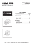
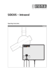
TorqLineBevel Manual
8/2/07
11:57 AM
Page 1
Installation,
Lubrication and
Maintenance
Instructions
CONGRATULATIONS!
Your decision to purchase a world class reducer from Grove Gear
will provide you with many years of trouble-free service if you adhere to the following
installation and maintenance instructions.
Phone: 800.894.0412 - Fax: 888.723.4773 - Web: www.clrwtr.com - Email: [email protected]
TorqLineBevel Manual
8/2/07
11:57 AM
Page 2
MECHANICAL WARNINGS & CAUTIONS
IMPORTANT INFORMATION
Please Read Carefully
The following
and
information is supplied to you for your protection and to provide you with
many years of trouble free and safe operation of your Grove Gear product.
Read ALL instructions prior to operating reducer. Injury to personnel or reducer failure may be caused by improper installation, maintenance or operation.
•
Written authorization from Grove Gear is required to operate or use reducers in man lift or people moving
devices.
•
Check to make certain application does not exceed the allowable load capacities published in the current
catalog.
•
Buyer shall be solely responsible for determining the adequacy of the product for any and all uses to which
Buyer shall apply the product. The application by Buyer shall not be subject to any implied warranty of
fitness for a particular purpose.
•
For safety, Buyer or User should provide protective guards over all shaft extensions and any moving
apparatus mounted thereon. The User is responsible for checking all applicable safety codes in his area and
providing suitable guards. Failure to do so may result in bodily injury and/or damage to equipment.
•
•
Hot oil and reducers can cause severe burns. Use extreme care when removing lubrication plugs and vents.
•
Reducers are not to be considered fail safe or self-locking devices. If these features are required, a
properly sized, independent holding device should be utilized. Reducers should not be used as a brake.
•
Any brakes that are used in conjunction with a reducer must be sized or positioned in such a way so as to
not subject the reducer to loads beyond the catalog rating.
•
Lifting supports including eyebolts are to be used for vertically lifting the gearbox only and no other
associated attachments or motors.
•
Use of an oil with an EP additive on units with backstops may prevent proper operation of the backstop.
Injury to personnel, damage to the reducer or other equipment may result.
•
Overhung loads subject shaft bearings and shafts to stress which may cause premature bearing failure
and/or shaft breakage from bending fatigue, if not sized properly.
•
•
Test run unit to verify operation. If the unit tested is a prototype, that unit must be of current production.
•
Mounting bolts should be routinely checked to ensure that the unit is firmly anchored for proper operation.
Make certain that the power supply is disconnected before attempting to service or remove any
components. Lock out the power supply and tag it to prevent unexpected application of power.
If the speed reducer cannot be located in a clear and dry area with access to adequate cooling air
supply, then precautions must be taken to avoid the ingestion of contaminants such as water and the
reduction in cooling ability due to exterior contaminants.
In the event of the resale of any of the goods, in whatever form, Resellers/Buyers will include the following language in a conspicuous
place and in a conspicuous manner in a written agreement covering such sale:
The manufacturer makes no warranties or representations, express or implied, by operation of law or otherwise, as to
the merchantability or fitness for a particular purpose of the goods sold hereunder. Buyer acknowledges that it alone has
determined that the goods purchased hereunder will suitably meet the requirements of their intended use. In no event
will the manufacturer be liable for consequential, incidental or other damages. Even if the repair or replacement
remedy shall be deemed to have failed of its essential purpose under Section 2-719 of the Uniform Commercial Code,
the manufacturer shall have no liability to Buyer for consequential damages.
Reseller/Buyers agree to also include this entire document including the warnings and cautions above in a conspicuous place and in
a conspicuous manner in writing to instruct users on the safe usage of the product.
This information should be read together with all other printed information supplied by Grove Gear.
Phone: 800.894.0412 - Fax: 888.723.4773 - Web: www.clrwtr.com - Email: [email protected]
TorqLineBevel Manual
8/2/07
11:57 AM
Page 3
ELECTRICAL WARNINGS & CAUTIONS
IMPORTANT INFORMATION
Please Read Carefully
Appropriate Grove Gear instructions provided with the motor and precautions attached to the motor should be read carefully
prior to installation, operation and/or maintenance of the equipment. Injury to personnel or motor failure may be caused by
improper installation, maintenance, or operation.
The following
and
information is supplied to you for your protection and to provide you with
many years of trouble free and safe operation of your Grove Gear product:
•
•
•
Disconnect power and lock out driven equipment before working on a motor.
•
•
•
Install and ground per local and national codes.
•
Never attempt to measure the temperature rise of a motor by touch. Temperature rise must be measured by
thermometer, resistance, imbedded detector or thermocouple.
•
Motors with automatic reset thermal protectors will automatically restart when the protector temperature drops
sufficiently. Do not use motors with automatic reset thermal protectors in applications where automatic restart will
be hazardous to personnel or equipment.
•
Motors with manual reset thermal protectors may start unexpectedly after the protector trips when the surrounding
air is at +20°Fahrenheit or lower. If the manual reset protector trips, disconnect motor from its power supply. After
the protector cools (five minutes or more), it can be reset and power may be applied to the motor.
•
•
Connect all protective device leads, marked P1, P2, etc., per instructions supplied with the motor.
•
For safety, Buyer or User should provide protective guards over all shaft extensions and any moving apparatus
mounted thereon. The User is responsible for checking all applicable safety codes in his area and providing
suitable guards. Failure to do so may result in bodily injury and/or damage to equipment.
•
Consult qualified personnel with questions and all electrical repairs must be performed by trained and qualified
personnel only.
•
•
•
•
For motors nameplated as “belted duty only”, do not operate the motor without belts properly installed.
Always keep hands and clothing away from moving parts.
The lifting support on the motor is not to be used to lift the entire machine. Only the motor attached directly to the
support may be safely lifted by the support.
Discharge all capacitors before servicing a single phase motor.
Misapplication of a motor in a hazardous environment can cause fire or an explosion and result in serious injury.
Only the end user, local authority having jurisdiction, and/or insurance underwriter are qualified to identify the
appropriate class(es), group(s), division and temperature code. Marathon Electric personnel can not evaluate or
recommend what motors may be suitable for use in hazardous environments. If a motor is nameplated for
hazardous locations, do not operate the motor without all of the grease and drain plugs installed.
Operation of a motor at other than its nameplate rating may result in fire, damage to equipment or serious injury to
personnel.
Motors and/or driven equipment should not be operated faster than their rated speed.
For inverter applications, follow the inverter manufacturer’s installation guidelines.
Make sure the motor is properly secured and aligned before operation.
In the event of the resale of any of the goods, in whatever form, Resellers/Buyers will include the following language in a
conspicuous place and in a conspicuous manner in a written agreement covering such sale:
The manufacturer makes no warranty or representations, express or implied, by operation of law or otherwise, as to the
merchantability or fitness for a particular purpose of the goods sold hereunder. Buyer acknowledges that it alone has
determined that the goods purchased hereunder will suitably meet the requirements of their intended use. In no event will
the manufacturer be liable for consequential, incidental or other damages. Even if the repair or replacement remedy shall be
deemed to have failed of its essential purpose under Section 2-719 of the Uniform Commercial Code, the manufacturer shall
have no liability to Buyer for consequential damages.
Resellers/Buyers agree to also include this entire document including the warnings and cautions above in a conspicuous place and in
a conspicuous manner in writing to instruct users on the safe usage of the product.
This information should be read together with all other printed information supplied by Grove Gear.
Phone: 800.894.0412 - Fax: 888.723.4773 - Web: www.clrwtr.com - Email: [email protected]
TorqLineBevel Manual
8/2/07
11:57 AM
Page 4
Mounting Positions / Lubrication
Mounting position must be specified on all orders, and included in the reducer description, so the correct amount of oil
is installed at the factory.
Mounting Positions
L
L
VENT LOCATION
R
R
OIL LEVEL
L
R
DRAIN PLUG
B3 I
B3
B6
L
L
R
R
R
R
L
L
B6 I
B6 II
B8 I
B8
R
R
L
L
L
L
R
R
V5
V5 I
V6
V6 I
Motorized Reducers & Gearmotors
The Reducer and Motor are assembled at the factory, and filled with the proper quantity of lubricant based on your
specified mounting position. Integral Gearmotors are supplied with 3 phase 230/460v totally enclosed, fan cooled (TEFC)
1750 rpm general purpose motors. Special integral gearmotors are available. Consult the factory for details.
Standard Integral Gearmotors and Motorized Reducers are assembled at the factory with the conduit box and the conduit
opening at the position illustrated in the dimensional section of the catalog. The user may rotate the body of the motor
to reposition the conduit box (in 90° increments from original position). The conduit opening may also be repositioned
at 90° increments from the original position. Both operations may be performed without disassembling the drive.
Lubrication
Size 8473 through 8973 Reducers and Gearmotors are filled with gear lubricant at the factory, to the correct level for the
mounting position specified on the order. The lubricants in the chart on the next page are recommended for continuous
operation in ambient temperatures of 30° to 125° F (0° to 50° C) and operating temperatures to 185° F (85° C). Consult
factory for recommendation for other ambient temperatures or intermittent duty.
If the mounting position is changed, the oil quantity must be adjusted to obtain the proper oil level.
Mounting position must be one shown above. Consult the factory if you are not certain of the correct oil level or
quantity. Consult the factory for mounting positions not shown.
Phone: 800.894.0412 - Fax: 888.723.4773 - Web: www.clrwtr.com - Email: [email protected]
TorqLineBevel Manual
8/2/07
11:57 AM
Page 5
Lubrication
Mobil
Corporation
Chevron
Corporation
Texaco
Inc.
Citgo Petroleum
Corporation
Shell Group
of Companies
Castrol
Limited
Mobilgear 630
Gear Compound EP ISO220
Meropa 220
EP Compound 220
Omala 220
Alpha SP220
Approximate Oil Capacity (pints) Triple Reduction
Mounting Position
Reducer Size
B3/B6I
B8
V5/V5I
V6/V6I
B6/B8I
B3I/B6II
8473
1.3
2.9
2.6
2.7
Contact Factory
3.5
8673
2.4
6.0
5.5
5.7
Contact Factory
7.2
8773
3.6
9.0
8.3
8.6
Contact Factory
10.8
8873
6.7
17.4
15.4
16.1
Contact Factory
20.1
8973
15.0
32.7
29.0
30.3
Contact Factory
37.8
81073
21.0
54.0
51.0
51.0
Contact Factory
71.0
Approximate Oil Capacity (pints) Quintuple Reduction(1)
Mounting Position
Reducer Size
8675
8775
8875
Unit
B3/B6I
B8
V5/V5I
V6/V6I
B6/B8I
B3I/B6II
Primary
1.0
1.8
1.5
1.5
Contact Factory
1.4
Secondary
2.4
6.0
5.5
5.7
Contact Factory
7.2
Primary
1.6
3.0
2.3
2.3
Contact Factory
2.3
Secondary
3.6
9.0
8.3
8.6
Contact Factory
10.8
Primary
5.1
7.4
6.1
6.1
Contact Factory
5.5
Secondary
6.7
17.4
15.4
16.1
Contact Factory
20.1
(1) Quin reduction units are compound units, the primary and secondary units are filled separately. Refer to the model table above and use the oil
capacities shown.
Important Selection Information
Lubrication
Read ALL instructions and safety precautions prior to
operating unit. Injury to personnel or unit failure may be
caused by improper installation, maintenance, or operation.
All GROVE GEAR Helical Bevel gearmotors and gear
reducers are supplied with the correct quantity of
lubricating oil for the mounting position specified at time
of order.
Check to verify that the application does not exceed the
capacities published in the current catalog.
Written authorization from GROVE GEAR is required to
operate or use gear units in man lift or people moving
devices.
The system of connected rotating parts must be free from
critical speed, torsional, or other type vibration, regardless
of how induced. The responsibility for this system analysis
lies with the purchaser of the gear unit.
Buyer shall be solely responsible for determining the
adequacy of the product for any and all uses to which the
buyer shall apply the product. The application by buyer
shall not be subject to any implied warranties of
merchantability or fitness for a particular purpose.
Before Installation
Review the approved mounting positions
and lubrication levels identified on page 4 of these
instructions. Do not deviate from the mounting positions or
lubrication levels shown without contacting the factory.
For transportation, the units are supplied as sealed
gearcases, i.e., in place of the breather plug, a socket head
plug is installed. The breather plug accompanies the unit in
the lubrication instructions and hardware envelope.
Phone: 800.894.0412 - Fax: 888.723.4773 - Web: www.clrwtr.com - Email: [email protected]
TorqLineBevel Manual
8/2/07
11:57 AM
Page 6
Lubrication & Installation
Before Operating
After final installation, install the breather plug in the
location specified on page 4 for the appropriate mounting
position.
Do not operate the unit without making sure
it contains the correct amount of oil. The oil level is correct
when surface of the oil is level with the lowest point of the
level plug shown on page 4.
Do not overfill or underfill with oil. This could
result in damage to unit and/or injury to personnel.
Changing Lubricant
After the first 100 hours of operation, drain out initial oil,
and refill. Thereafter, oil should be changed at least every
7500 operating hours (15,000 for synthetic oil lubricant) or
every 18 months (36 months for synthetic oil lubricant) —
whichever occurs first.
Oil should be changed with greater
frequency if unit is used in a severe environment such as
dusty or humid.
If the unit cannot be located in a clear and
dry area with access to an adequate cooling air supply,
then precautions must be taken to avoid ingestion of
contaminants such as water, and to avoid a reduction of
cooling ability due to exterior contaminants.
Wear protective clothing and eye shields
when installing or maintaining unit and machine.
Oil, housings, and other components can
reach high temperatures during operation, and can cause
severe burns. Use extreme care when removing lubrication
plugs and vents while servicing the unit.
Variations From Normal Conditions
Input speeds other than 1750 rpm, may require an
adjustment in the oil level. Consult GROVE GEAR for special
lubricant recommendations when operating at higher or
lower speeds.
MOBILGEAR 630 LUBRICANT is a heavy duty industrial
gear lubricant containing sulfur phosphorous antiwear
additives. Lubricants of this general type and meeting the
above specifications may be substituted where
MOBILGEAR LUBRICANTS are recommended.
Lubricant selected must be compatible with nitrile rubber
seals. For ambient temperature above 125°F (52°C), below
30°F (0°C), operating temperature above 185°F (85°C), or
intermittent duty, consult the factory.
ALL TEMPERATURE SYNTHETIC
75W-90 LUBRICANT (MOBILUBE SHC® 75W-90)
MOBILGEAR SHC 75W-90 LUBRICANT is a premium gear
box lubricant which is recommended for Helical Bevel Gear
Drives in most applications, especially those subject to low
start up temperature and/or high operating temperature.
This lubricant is a synthesized hydrocarbon based material
and a sulfur-phosphorous gear lubricant additive which
provides longer lubrication intervals because of its
increased resistance to thermal and oxidative degradation.
This decreases maintenance costs. Further economy is
realized because of the increased efficiency of units
lubricated with MOBILGEAR SYNTHETIC LUBRICANT. This
lubricant can be operated at temperatures considerably
above 185°F (85°C). However, the factory should always be
contacted prior to operating at high temperatures as
damage may occur to seals or other components. Lubricant
manufacturer and GROVE GEAR should be contacted when
substituting a premium lubricant where SYNTHETIC
lubrication is recommended. GROVE GEAR should also be
contacted for proper lubricant selection for ambient
temperatures below 30°F (0°C) or intermittent duty.
Do not mix nonsynthetic and synthetic oil in
the unit.
If unit is used in the food or drug industry
(including animal food) consult the petroleum supplier or
GROVE GEAR for recommendation of lubricants which
meet the specifications of FDA, USDA and/or other
authoritative bodies having jurisdiction. Standard lubricants
are not suitable for these applications or these industries.
APPROVED LUBRICANTS
LUBRICANT
AGMA
NUMBER
ISO-ASTM
VISCOSITY GRADE
Mobilgear 630
5 EP
220
For continuous operation of Helical Bevel Gear Drives
with ambient temperature of 30-125°F (0 to 52°C) and
operating temperature to 185°F (85°C).
Installation
Make certain that the power supply is
disconnected before attempting to service or install the
unit, or remove or install any components. Lock out the
power supply, and tag it to prevent unsuspected
application of power.
Phone: 800.894.0412 - Fax: 888.723.4773 - Web: www.clrwtr.com - Email: [email protected]
TorqLineBevel Manual
8/2/07
11:57 AM
Page 7
Lubrication & Installation
SHIELD ALL ROTATING PARTS
For safety, purchaser or user should provide
protective shields over all shaft extensions and any moving
apparatus mounted on the unit. The user is responsible
for checking all applicable safety codes in his area and
providing suitable shields.
A unit cannot be used as an integral part of
a machine super-structure which would impose additional
loads on the unit other than those imposed by the torque
being transmitted, or by any shaft mounted power
transmitting device such as sprockets, pulleys, or couplings.
Units ARE NOT to be considered fail safe or
self locking devices. If these features are required, a
properly sized, independent holding device must be utilized.
For safe operation and to continue the unit
warranty, when installing, reinstalling, or replacing a
factory installed fastener for servicing purpose, or to
accommodate the mounting of guards, shields or other
light load imposing devices, or for mounting the unit, it
becomes the responsibility of the purchaser or user to
properly determine the quality, grade of fastener, thread
engagement, load carrying capacity, tightening, torque, and
the means of torque retention.
Couplings
Flexible couplings to input and output shafts are
recommended because they minimize excessive bearing
and shaft loading caused by misalignment. Follow coupling
manufacturer’s installation directions.
Shaft Mounted Models
GROVE GEAR recommends application of an anti-seize
compound, such as Dow-Corning® 1000 High
Temperature Anti-seize Paste or Never-Seez®, to the
driven shaft during installation. This assists in preventing
fretting corrosion and aids in unit removal. Driven shaft
should be supported independently with pillow block
bearings. A suitable Torque Arm must be provided and can
be ordered separately (not supplied) to keep unit from
rotating. A torque arm pad can be attached to any of the
four available mounting surface locations of the unit. Install
and position Torque Arm at 90° angle to a line drawn
between the center of the output hollow bore and the bolt
that attaches the Torque Arm to the Torque Arm Pad of the
unit. The Torque Arm should be positioned to be in
tension, NOT compression, based on output rotation of the
gear drive. (Refer to Figure 1). A rigid torque arm an cause
bearings to “load up” and cause premature bearing failure.
To prevent this, provide a slight amount of “float” at the
torque arm pivot points.
Inspect shafts and components for paint,
burrs, or other imperfections before installing components.
Do not use excessive force or pounding to install
components onto unit shafts, as this may cause damage to
shafts, bearings, or gears.
Preventative Maintenance
Keep shafts and vent plug clean to prevent foreign particles
from entering seals or gear case. Inspect periodically for oil
leaks.
Sheaves and Sprockets
When mounting sheaves or sprockets, they should be
located as close to the Helical Bevel Gear Drive as possible.
Excessive overhung load could result in premature failures
of bearings or shaft. Refer to the general catalog or contact
your local distributor for overhung load ratings.
Any brakes that are used in conjunction with
a unit must be sized or positioned in such a way so as to
not subject the unit to loads beyond the capacities
published in the current catalog.
Flange Mounted Units
Units with the flange mount accessory are to
be mounted and supported by the mounting flange only.
The mounting pads on the housing are not to be used in
conjunction with the mounting flange to support the unit.
Shaft Mounted Units With Mounting Flange
There must be concentricity between the driven shaft and
the machine register that accepts the mounting flange pilot
to prevent misalignment between the hollow shaft of the
drive and the driven shaft.
Figure 1
+ 90
- 30
Phone: 800.894.0412 - Fax: 888.723.4773 - Web: www.clrwtr.com - Email: [email protected]
TorqLineBevel Manual
8/2/07
11:57 AM
Page 8
Lubrication & Installation
Shaft Output Units With Mounting Flange
If coupling to shaft – flexible couplings are recommended
to minimize excessive bearing and shaft loading caused by
misalignment. Follow coupling manufacturer’s installation
directions.
The exterior holes on this drive are for
mounting the drive or drive accessories (mounting flange,
couplings, sprockets, etc.). They are not to be used for
lifting the drive or any driver/driven equipment. The lifting
eye included on this drive is to be used to vertically lift the
drive only and no other associated attachments or motors.
Electric Motor and Hydraulic Motor and Pump
Installation Instructions
For “C” Flange and Hydraulic Flange Units
1. Be sure all of the paint and masking have been
removed from the face and pilot of the flange. Check the
input bore to be sure it contains an adequate amount of
anti-seize compound, which is normally installed at the
factory. This compound will inhibit fretting corrosion
between the motor or pump shaft and the unit bore.
2. Install the key (if round bore) to the maximum depth
of the keyway provided in the bore.
3. Align keyways or splines of motor or pump and bore of
unit and install motor or pump into frame.
4.
GROVE GEAR “C” flange reducers and
Hydraulic Flange Reducers are designed to accept motors
with shafts that do not exceed the maximum specified by
the N.E.M.A. or SAE standards. If the motor or pump shaft
bottoms out before the motor or pump flange seats
against the reducer flange face, the motor or pump shaft
length must be adjusted to N.E.M.A. or SAE standards.
5. Secure the motor or pump to the unit. Capscrews and
lockwashers are provided with “C” flange units.
6. Tightening torques for mounting bolts are provided in
the chart below.
CAPSCREW TIGHTENING TORQUE
Grade 5 Capscrews (dry, without lubricant)
Capscrew Size
1/4 NC
5/16 NC
3/8 NC
1/2 NC
5/8 NC
3/4 NC
Tightening Torque
(Ft. - Lbs.)
8
16
29
71
143
251
Mounting bolts, coupling fasteners, and
other power transmitting devices should be routinely
checked to ensure that all parts of the unit are firmly
anchored to provide proper operation. (Loose fasteners
can cause alignment problems and excessive wear). Check
end play in shafts. Noticeable movement might indicate
service or parts replacement.
Make certain that all tools and other items
are clear from rotating parts before starting machine. Stand
clear, and start machine slowly to be sure all components
are secure and operating properly.
Test run unit to verify operation. If the unit
being tested is a prototype, that unit must be of current
production configuration.
GROVE GEAR has Sales Offices and a network of Industrial
Power Transmission Distributors that can serve your needs
worldwide. Check the Yellow Pages for one near you or
contact the factory sales office.
5968G/1K/8-07/BH/BP
Phone: 800.894.0412 - Fax: 888.723.4773 - Web: www.clrwtr.com - Email: [email protected]