1
TCOM Viewer User's Manual
© Copyright 2012
Orenco Systems, Inc.
Table of Contents
Topic ................................................................................................ Page
TCOM Viewer Overview ......................................................................... 1
TCOM Viewer Requirements.................................................................. 2
Computer Requirements .....................................................................................2
TCOM Viewer Installation.................................................................................2
Communication Requirements ...........................................................................2
TCOM Viewer Setup................................................................................ 4
Adding a New Site..................................................................................... 6
Choosing a method for adding a New Site .........................................................6
Adding a Site using the Automated Process .......................................................6
Communication methods....................................................................................7
Adding a Site using the Manual Process.............................................................9
Importing an Orenco provided Configuration File ............................. 11
Connecting and Logging on to a TCOM Panel .................................... 12
Site List Information.........................................................................................12
Selecting a Site for Viewing.............................................................................12
Connection Choices Dialog Window ...............................................................13
While Connecting and Online ..........................................................................13
Logging Off ............................................................................................. 14
Using One-Time Connect to make a temporary connection ............... 14
Graphic View .......................................................................................... 15
Entering Graphic View.....................................................................................15
Overriding Devices and Parameters in Graphic View ......................................16
Current Point Status..........................................................................................17
Override Settings ..............................................................................................18
Backup Programming .......................................................................................18
Logs/Plots ................................................................................................ 19
Determining the Log Content Available for a Panel.........................................19
Types of Logs...................................................................................................20
Downloading and Viewing Logs ......................................................................20
Exporting Logs .................................................................................................22
Fast Plotting......................................................................................................22
Defined Plotting ...............................................................................................24
Terminal View ........................................................................................ 26
Entering Terminal View ...................................................................................26
Terminal Screen Navigation .............................................................................27
Run Mode Menu...............................................................................................28
Page Select Menu .............................................................................................29
Adjusting Point Settings ...................................................................................31
Program Backup ...............................................................................................31
Special Considerations .....................................................................................31
Overriding a Digital Point to On ......................................................................32
Overriding a Digital Point to Off......................................................................33
Constant Override of a Numeric Point Value ...................................................34
Set Point Adjustment of a Point Value .............................................................35
Adjustment of a Point Value with a Timer .......................................................36
Point Menu .......................................................................................................37
Change Time/Date............................................................................................39
Logs..................................................................................................................40
Maintenance Log ..............................................................................................41
TCOM Viewer Overview
TCOM Viewer software is designed to provide System Operators a tool to communicate with TCOM
panels locally or remotely (depending on system configuration). The built-in Terminal View allows
monitoring or adjusting of the operating settings through a text driven series of menus, similar to other
programs that may have been used in the past. As a standard offering, TCOM Viewer also offers
improvements in the ability to view, plot, and export historical log data.
As an optional add-on purchase for each site, TCOM Viewer can be enhanced to support graphical
views and defined plots. The required programming by Orenco’s design staff is stored in a
configuration file that can be imported into TCOM Viewer. A quote for a configuration file for a given
site can be requested from Orenco. A configuration file can be designed for new or existing panels.
EIN-TCOM-SW-1
Rev. 1.3 © 03/26/12
Page 1 of 42
TCOM Viewer Requirements
Computer Requirements:
TCOM Viewer is designed to run on computers running Windows XP® or newer. Depending on the
computer and the method of communication used to connect to the panel, additional accessories for the
computer may be required. In most cases, adaptors using the computer’s USB ports are available to add
any desired connectivity options that may not be already built into the computer. The most commonly
needed accessories are a modem and/or a 9-pin serial adaptor. Another accessory that is available from
Orenco is a Bluetooth adaptor that can be plugged into the TCOM panel to allow a wireless connection
to a nearby computer with Bluetooth capabilities. Some recommended products that have been tested
with TCOM Viewer are listed below:
Description: USB external modem for communication over a phone line
Manufacturer: Zoom®
Model: 3095
Website: http://www.zoomtel.com/products/dial_up_external_usb.html
Description: USB to 9-pin serial adaptor for a direct connection to the panel using a null modem cable
Manufacturer: Tripp-Lite/KeySpan®
Model: USA-19HS
Website: http://www.tripplite.com/en/products/model.cfm?txtModelID=3914
TCOM Viewer Installation:
Prior to installing TCOM Viewer, it is recommended that any Windows® service packs or security
updates from Microsoft® are installed. Internet access is required during the TCOM Viewer install
process as the .NET framework and SQL Server Compact prerequisites from Microsoft® will be
downloaded and installed if they are not already on the computer.
TCOM Viewer can be downloaded from our website from the following location:
http://www.orenco.com/controls/tcom_viewer.cfm
Once the TCOM Viewer software is downloaded, the installer can be unzipped and run. The installer
program will prompt the user for input at various steps during the process. Once the installation has
completed, the installer and downloaded zip file can be deleted.
Communication Requirements:
To establish a connection with the TCOM panel controller, several options are possible.
• Connection via direct connection to the TCOM Panel controller. This connection may be via an
RS232 serial port connection or through USB to Serial converter device, or through the use of a
Bluetooth ™ wireless receiver mounted inside the TCOM Panel. Any of these options are
considered a “direct” connection to TCOM Viewer. Obviously, the User must be physically at the
Site to make a direct connection to a TCOM Panel controller.
EIN-TCOM-SW-1
Rev. 1.3 © 03/26/12
Page 2 of 42
• Connection remotely via Telephone Modem. This method can be used if the TCOM Panel has a
telephone line connected to it for remote monitoring. The User’s computer must also have a
Telephone Modem device. The TCOM Viewer software will dial the phone number of the TCOM
Panel and make a connection.
• Connection via local Ethernet Network (LAN, Local Area Network). This method requires the
User’s computer to be connected to the same 10/100BaseT Ethernet network as the TCOM Panel.
• Connection remotely over the Internet (WAN, Wide Area Network). This method requires that the
TCOM Panel is installed with access to the Internet and with the capability to be accessed from a
remote computer.
Using any of the options above requires that the TCOM Viewer software is aware of the capabilities of
the user’s computer and what site communications settings are required to access the TCOM Panel (i.e.
phone number or network IP address, etc.).
EIN-TCOM-SW-1
Rev. 1.3 © 03/26/12
Page 3 of 42
TCOM Viewer Setup
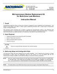
A recommended first step after opening TCOM Viewer for the first time is to configure the computer
settings and user preferences found in the TCOM Viewer Setup dialog window. To open the TCOM
Viewer Setup dialog window, select the FILE menu and pick the “TCOM Viewer Setup” choice. Much
of the information entered here will be used as Default settings whenever a new site is added. Some
settings can be uniquely overridden during the Site Setup for any sites where the default settings will
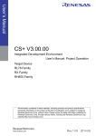
not work. The TCOM Viewer Setup dialog window is shown in figure 1.
Figure 1 TCOM Viewer Setup window
The most commonly used connection types are the “Modem Port” and the “Direct Port”. The software
will provide a drop down list with the “COMx” ports that are currently present on the user’s computer.
Computers without RS232 ports (9-pin male connectors) may use USB to Serial adapters that will not
appear in the list unless they are plugged into the computer at the time.
Notes:
Timeout values specify the amount of dead/inactivity time that will be allowed before the software
automatically disconnects from the TCOM Panel, while in the graphic view.
The Modem Init value is used to initialize the Modem device. Usually, the standard
“AT&FE0&C1&D2” entry is sufficient.
The Telnet Port# settings are determined by the individual Site needs, but commonly used values are
23 and 1023.
EIN-TCOM-SW-1
Rev. 1.3 © 03/26/12
Page 4 of 42
The Terminal Colors (Text Color/Background Color) selected will be used as the initial color scheme
for the terminal view for any new connection.
The Ignore CD (Carrier Detect) checkbox is a rarely needed option for modem use on some nonstandard computer configurations, such as in a virtual machine environment. This should not be
checked in most cases.
The Default View setting specifies the starting view, once a new connection is established with a
panel. The choices are graphic view or terminal view. If a site does not have a configuration file with
graphics, it will always start in the terminal view.
The Logon Name and Logon Password entries allow default logon information to be entered. Each
time a new site is created, these default values will initially be presented in the Site Properties window,
where they can be confirmed or changed as needed for each site.
EIN-TCOM-SW-1
Rev. 1.3 © 03/26/12
Page 5 of 42
Adding a New Site:
Using the Main window Tab labeled Sites, a new Site Definition can be created and saved for future
use. Clicking on the Add Site menu button will lead the User through a sequence of actions to define a
Site. A completed site definition will consist of applicable communications settings for making a site
connection as well as information used to uniquely identify a specific TCOM panel. Note that several
types of communication parameters can be defined as the user may be on site for a direct connection
and also access the site remotely at another time. If only one type of connection is defined to begin
with, others can be added at a later time by editing the site.
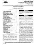
Choosing a method for adding a New Site
To begin the process of adding a new site, click the Add Site button in the Sites Tab section of the
Main window. The User is offered a choice to automate the process or to enter the Site information
manually (See figure 2 below). Typically, the Automated Add Site choice is recommended. The
Manual process may be required if the automated process is attempted, but not successful. Some older
TCOM panels may require the manual process.
Figure 2 Add Site Choices
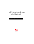
Adding a Site using the Automated Process
Using the automated process, TCOM Viewer will attempt to make a trial connection using the
communications settings entered by the user (see figure 3). Many of the available settings will show
default values based on the settings that were entered in the TCOM Viewer Setup screen (see page 4)
EIN-TCOM-SW-1
Rev. 1.3 © 03/26/12
Page 6 of 42
Figure 3 Site Properties window
Communication methods: Four methods of communication can be defined, but only one defined type
is required for the trial connection. The four connection types are:
1. Modem: The Modem option is used for connecting to a TCOM panel over a phone line from a
remote location. The computer running TCOM Viewer must have a modem and access to a phone
line. The phone number should be entered with any prefixes or area codes required to call from the
user’s location to the panel’s location. For the modem port setting, select a specific COM port to
use or select “AUTO” to use the setting that was defined in the TCOM Viewer Setup. The baud
rate default of 38400 may need to be reduced if the phone connection is unstable. If adjustments are
needed for the modem for a specific site, additional modem commands can be entered in the “Alt
Modem Init Commands” area.
2. Direct: The Direct option is used for connecting to a TCOM panel while at a site. There are
multiple options for connecting directly to the panel. The direct connection available on the board
is a 9-pin RS-232 port. Depending on your computer, additional adaptors and software may need to
be installed. Commonly, a wired cable (null-modem) or wireless Bluetooth connection kit is used.
For the port settings, select a specific COM port to use for the device or select “AUTO” to use the
setting that was defined in the TCOM Viewer Setup. As of the release date of this manual, all
TCOM panels are set to use the default baud rate of 9600. Unlike the modem, the direct baud rate
must match the setting of the panel or it will not be able to connect.
3. LAN: The LAN (Local Area Network) option is available for connecting to a TCOM panel that has
been configured for, and connected to, a network via a CAT5 cable plugged into the TCOM
board’s RJ45 connector. The user’s computer must also be configured for, and connected to, the
EIN-TCOM-SW-1
Rev. 1.3 © 03/26/12
Page 7 of 42
same network. This typically means the user would be at the site or using a VPN to gain remote
access to the network the panel is connected to. In TCOM Viewer, the IP or Hostname and Telnet
Port# setting must be set to match the settings of the TCOM panel, which would have been
determined under the guidance of the local network administrator.
4. WAN: The WAN (Wide Area Network) option is similar to the LAN connection, but is used for
connecting to a TCOM panel using the Internet from a remote location. Both the computer and the
TCOM panel must have access to the Internet. Additionally, the network the TCOM panel resides
in must be configured to allow a path for an outside connection to get through to the panel.
Typically, this means the firewall/router for the network where the TCOM panel is located would
need to be configured to allow port forwarding. In TCOM Viewer, the IP or Hostname and Telnet
Port# setting is based on the configuration of the firewall and will most likely be different than the
local network settings defined in the TCOM panel itself. For more information on configuring
TCOM panels for remote access over the Internet, see Orenco document number: EIN-CPTCOM-19
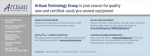
Once the connection information is entered for one or more methods, select the preferred “Default
Connection Type”, and click “OK” to continue. The next screen will ask which connection method
should be used to communicate with the panel (see figure 4). Once the proper option is selected, click
“Connect” to initiate the connection to the panel.
Figure 4 Connection Choices window
If the trial connection is successful, TCOM Viewer will obtain the unique panel identification which is
known as the Custom# and Quote# values from the actual field control panel and display a
confirmation screen (see figure 5). Optionally, enter a description of the site for your own reference
under the “Site Expanded Description” to complete the add site process. If the trial connection was not
successful, the process can be cancelled or the site properties screen can be returned to, where
adjustments can be made, followed by another attempt at a trial connection.
EIN-TCOM-SW-1
Rev. 1.3 © 03/26/12
Page 8 of 42
Figure 5 New Site Custom# and Quote# confirmation
Adding a Site using the Manual Process
If a Manual process is selected, the user will be required to enter a Custom# and a Quote# for the Site
and optionally, to enter a description of the site for reference under the “Site Expanded Description”
(see figure 6). The Custom# and Quote# information is needed to uniquely identify the Site and to
create a properly named data folder to hold logs and reports obtained from the Site. These numbers are
also used to link the site to any Orenco provided configuration files, including those with Graphic
Views. All Custom panels produced by Orenco should have these numbers included on the wiring
diagram and other paperwork sent with the panel. If none of the numbers are known, a One-Time
Connect can be used to connect to the panel and look for the numbers in the Terminal view (see page
14). The Manual process is only recommended if the Automated process cannot be used.
EIN-TCOM-SW-1
Rev. 1.3 © 03/26/12
Page 9 of 42
Figure 6 New Site Custom# and Quote# entry
After entering the required and optional information for the New Site Information screen, click “OK”.
The site properties screen will be displayed next. The site properties screen is similar to the one used
during the automated add site process and a description of it can be found there (see figure 3 and the
applicable “Communication methods” notes beneath it). For the manual add site process, once the
communication information is entered on the site properties screen, the process will be completed
when “OK” is clicked.
EIN-TCOM-SW-1
Rev. 1.3 © 03/26/12
Page 10 of 42
Importing an Orenco provided Configuration File
TCOM Viewer supports an optional “configuration file” that can be obtained from Orenco for each
site. The configuration file contains site specific information to support enhanced features, such as
graphical views, point and log names, and defined plots.
In most cases, it is recommended that the configuration file be imported after the site has been created
through the “Add Site” process. If the site exists, TCOM Viewer will simply update the site with the
new enhancements and no other action is required. If the Site Definition does not already exist (or does
not match), TCOM Viewer will automatically create a new site. The new Site will appear on the list of
Sites. If the site is new, the User must select that Site and perform an Edit Site process using the menu
above the Site List. The User must define the communications settings for the new site (i.e. phone
number, IP address etc.) before the first connection attempt.
To import a Configuration File, use the File menu and the “Import Site Config File” submenu item.
When initiated, the program will prompt the User for the location of the Configuration File and will
move the Configuration File into the existing, or newly created, site folder. Upon completion, the site
list Status column should update to indicate the presence of the configuration file and whether it
includes graphic views.
EIN-TCOM-SW-1
Rev. 1.3 © 03/26/12
Page 11 of 42
Connecting and Logging on to a TCOM Panel
Site List Information
The Main Window shown below displays a list of sites that have been added. The list can be sorted by
“Name” or “Expanded Info” by clicking the column header at the top. In addition, the Status column
indicates whether or not the site has a graphics configuration file, a non-graphics configuration file, or
only a site definition file. A symbol in the Status column indicates the site has only a site definition
file. A symbol in the Status column indicates the site has a non-graphics configuration file. This file
will provide the user with the names of the log files and all the points in the TCOM panel. A symbol
in the Status column indicates the site has a graphics configuration file which give the user the names
of the log files and points plus graphics screens built to show the status of the system.
Figure 7 Main Window
Selecting a Site for Viewing
Using the Main window Tab labeled Sites, select one of the existing Site Definitions and press the
Connect Button at the bottom of the window area.
EIN-TCOM-SW-1
Rev. 1.3 © 03/26/12
Page 12 of 42
Connection Choices Dialog Window
The software will display the Connection Choices dialog window (see figure 8). This window will give
the User the ability to choose one of the possible connection methods. If a particular method is not
defined, it will appear grayed out and not be selectable. The Timeout value may be overridden as well.
Figure 8 Connection Choices window
While Connecting and Online
When a connection is in process, the status of the connection process is displayed at the bottom of the
Main window along with a sliding bar to indicate that the software is working on the last command.
Normally the Status will progress through a sequence such as:
1. Connecting or Dialing, depending on the communications method chosen.
2. Logon 1, 2, 3, 4, as the connection is established and the proper authorization is submitted.
3. Online when the connection has been successfully established.
4. After disconnected or timed out, the status will return to the Not Connected status.
If an error occurs, an error code will be displayed and the Status will return to the Not Connected
state.
Once a successful connection has been made, the live session will automatically move to either the
Graphic View or the Terminal View. A preference for the starting view can be set in the TCOM
Viewer Setup. If a site does not have a configuration file with graphics, it will always start in the
terminal view.
When in Online status, operations such as updating the Graphic real-time data values or retrieving log
data will cause the Status information to rapidly change which is normal.
While connected, the Tabs for “Terminal View”, “Logs/Plots”, and optionally “Graphic View”, can be
selected to gain access for viewing panel status and downloading historical information. Each of these
areas is described in this manual.
EIN-TCOM-SW-1
Rev. 1.3 © 03/26/12
Page 13 of 42
Logging Off
To log off a connected Site, use the Disconnect button next to the TCOM Viewer logo at the top of the
Main window. After a few seconds, the Status line at the bottom of the window will show Not
Connected.
If TCOM Viewer is left in the Graphic View while Online, there is a timeout that will occur and cause
the software to automatically disconnect. This timeout value may be set on the TCOM Viewer Setup
window that can be accessed via the File menu on the Main window.
You must Disconnect prior to connecting to any other Site.
Using One-Time Connect to make a temporary connection
One-Time Connect is meant for temporary access to a site and requires only the minimum necessary
connection information. The One-Time Connect is chosen by clicking the Actions menu at the top of
the main window and selecting the One-Time Connect item. When a One-Time Connect is used,
nothing about the connection is saved.
Click the Actions menu at the top of the Main window and select the One-Time Connect item to
begin the process. The Site Properties dialog window will appear. You only need to enter parameters
that pertain to the specific communications method being used. Entering “AUTO” for Port numbers
will just assume the Default COMx ports specified in the TCOM Viewer Setup dialog window
described above. The Site Properties window using One-Time connect is similar the one used during
the “Add Site Automatically” process and a description can be found there (see figure 3 and the
applicable “Communication methods” notes beneath it)
EIN-TCOM-SW-1
Rev. 1.3 © 03/26/12
Page 14 of 42
Graphic View
Graphic Views of the TCOM Panel’s controlled equipment can provided with a Graphics
Configuration File, which is an optional data file that can be provided by Orenco Systems.
One or more custom Graphic Views may be available and provided within the Graphics
Configuration File. A Site listed on the Main window, Sites Tab, that has Graphic Views available
will show a small painter’s pallet icon ( ) in the Status column of the list. If this icon is not present
then no graphics have been provided. A Preview Graphic Views icon can be selected to show a
preview of the graphics views without being connected.
Entering Graphic View
To make use of the Graphic Views, first connect and logon to the desired Site. Depending on the
setting in the TCOM Viewer Setup, the Graphic View may come up by default. If a graphic view is
available but does not come up after the Status line shows Online, click the Graphic View Tab. A
window will pop up asking permission to switch to “Make Graphics View Active”. Answer “Yes” to
this window and the first Graphic View will be displayed. The data and animated objects on the
Graphic View will update their values/appearance approximately every 5 seconds. Standard format
views of Floats and Pumps will change appearance with the current state of those devices.
If there are multiple Graphic Views, the top center information pane will show “1 of 4” or however
many views are defined. Clicking (left mouse button) in this information pane will allow a change of
views. Each time the view changes, the Status line at the bottom of the Main window will show steps
taken to fill the new graphic with real time data.
EIN-TCOM-SW-1
Rev. 1.3 © 03/26/12
Page 15 of 42
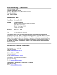
Device override allowed.
Device is not overridden.
Point override allowed.
Point is overridden.
Device override allowed.
Device is overridden.
Point override allowed.
Point is not overridden.
Point override not
allowed.
Device override is
not allowed.
Figure 9 Graphic View Tab window
Overriding Devices and Parameters in Graphic View
Devices and Parameters that permit the user to override them or modify their values will be shown with
a black outline around them and will respond to being clicked with the mouse (left mouse click).
Parameters that have been overridden will have the text “OVR” next to them. Devices that have been
overridden will have an “O” next to them. When an object that can be overridden is clicked, an
Override Dialog window will appear.
EIN-TCOM-SW-1
Rev. 1.3 © 03/26/12
Page 16 of 42
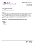
Figure 10 Override Dialog window
The top section of the Override Dialog window shows the current value/status of the TCOM control’s
Point value. The example shown is a digital, ON/OFF, type value, Point# 465, that is currently OFF
and its Status is “Auto”, meaning automatic. The status and override settings options are explained on
the following page. Once the desired point adjustments have been entered, click “Do Override” to
implement the changes or click “Cancel”.
Current Point Status
The “Current Point Status” may be any of the following:
• “Auto” means automatic. A Point in automatic mode will rely on the TCOM custom logic
programming to determine the value of the Point.
• “Const” means Constant. A Point with a status of Constant is one that is currently set to a fixed
value and is not influenced by the TCOM logic programming.
• “Ovr” means Overridden to ON or OFF. An Overridden Point is set to the current value (ON or
OFF) and is not influenced by the TCOM logic programming.
• “Ovr/Timer” means Timed Override. A Timed Override status means that the current value has
been overridden for a specified time interval. When the remaining time has expired, the Point value
and status will return to a previous setting.
EIN-TCOM-SW-1
Rev. 1.3 © 03/26/12
Page 17 of 42
Override Settings
The “Override Settings” area will display the available choices for overriding a given point.
The choices are used for the following purposes:
• “Restore Factory Default” can be used to return the Point to the factory default setting, which may
result in a specific value being set or returning the Point to automatic status.
• “Override Value” can be used to specify a new value to be used for overriding the Point.
• “Timer” or “Optional Timer” is used to specify a time interval for an override to remain in force.
After the time duration elapses, the Point value will revert back to the previous setting. Depending
on the Point being adjusted, a “Timer” entry may be required, optional, or not available. When not
available or the timer value is left blank, the new value specified for the point will be permanent*.
CAUTION: Critical Points, such as the one shown in the example, control the ON/OFF cycling of a
pump. Overriding this type of Point using an “Override Value” without an “Optional Timer” value will
cause the equipment controlled to remain ON or OFF CONTINUOUSLY! It is generally safe to set any
Point using the “Restore Factory Default” option as logic should ensure that the Point will be set to a
reasonable value.
*Note (Backup Programming):
TCOM programming is stored in memory that is maintained with a battery if there is a power
interruption. A second copy of the programming can be stored in non-volatile (flash) memory, and this
copy of the programming will automatically be loaded if the other programming is lost due to a
problem, such as a dead battery. The original factory programming in the TCOM panel is backed up to
the non-volatile memory, prior to shipment of the panel. To ensure that parameter changes are
permanently saved, the programming should be backed up to non-volatile memory after making the
changes. This can be done using the “Backup Programming” option under the “Actions” menu. It is
recommended that the panel be in a stable condition (i.e. free of alarms) prior to using the “Backup
Programming” command. If there are several parameter adjustments to make, all of the changes can be
completed first, followed by a single “Backup Programming” command at the end. Older TCOM
panels may not be compatible with the “Backup Programming” command. If an error message is
received after selecting “Backup Programming”, please contact Orenco for assistance.
EIN-TCOM-SW-1
Rev. 1.3 © 03/26/12
Page 18 of 42
Logs/Plots
While online with the TCOM Panel, the history logs containing data can be downloaded and viewed by
selecting the Logs/Plots Tab on the Main window.
Figure 11 Logs/Plots Tab window
Determining the Log Content Available for a Panel
A TCOM Panel is customized for each design and the log structure may vary from system to system.
For sites that include a configuration file (with or without graphics), the name of the logs will be
available when making a selection and the downloaded logs will include point descriptions. For sites
without a configuration file, only the log number or point number will be displayed. To determine the
structure of the logs when no configuration file exists, there are a couple of options. The first option is
to review the documentation that shipped with the control panel for information about which of the
possible Logs may be in use and what data values they will hold. A second option is to look up the log
information using the terminal view first and then return to the Logs/Plots Tab when ready to
download the log(s) (see page 40).
EIN-TCOM-SW-1
Rev. 1.3 © 03/26/12
Page 19 of 42
Types of Logs
There are four types of logs and there may be more than one log available of each type.
• User Log, is a programmable data log that can save up to 4 data values along with a date/time
stamp. User logs include site specific alarms and daily flow history. Most of the commonly needed
information for reports and long-term performance tracking can be found in the User Logs. The
logs may be viewed on the computer screen, exported to a CSV file, and the data can be plotted as a
line plot versus time.
• Activity Log, is a programmable data log that can save a single data value, recording its transitions
and duration. Activity logs are available for tracking the recent activity of a specific input (e.g.
floats) or output (e.g. pumps). Activity logs are mainly used for troubleshooting. The logs may be
viewed on the computer screen, exported to a CSV file, and the data can be plotted as a line plot
versus time.
• Alarm Log, is designed to capture TCOM controller events such as power failures and callout
activity. This log may be viewed on the computer screen, and exported to a CSV file.
• Maintenance Log, is used to allow operators and service personnel to record actions taken. This
log may be viewed on the computer screen, and exported to a CSV file.
Downloading and Viewing Logs
To view a log, click the menu on the Logs/Plots Tab window and select “Show..” from the secondary
menu. The Log Retrieval Options dialog window is shown (see Figure 12) to allow the User to select
the Log# or Point#, and the Date Span. The Date Span may be one of the suggested time periods or the
user may select “Pick Oldest Date” to choose the oldest data date from the calendar control. Once the
desired options are entered, click “OK” to start the log download. As the log is downloaded, the status
bar at the bottom of the screen will update the progress until the download has completed. If necessary,
an in progress log download can be cancelled using the “Abort Current Task” command found under
the “Actions” menu.
EIN-TCOM-SW-1
Rev. 1.3 © 03/26/12
Page 20 of 42
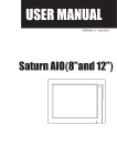
Figure 12 Log Retrieval Options window
Once the Log has been retrieved, it will be displayed on screen in a grid (see figure 13). The user may
change the sort order of the data by clicking on the “Sort” column. The column widths can be adjusted,
if necessary.
Figure 13 Retrieved Log Example
EIN-TCOM-SW-1
Rev. 1.3 © 03/26/12
Page 21 of 42
Exporting Logs
The Export button can be clicked to save the log data currently displayed on the screen to a CSV
(comma separated value) format file. The default location for saving the exported file is the site folder,
but any location can be specified. The CSV file may be loaded into Microsoft Excel, Microsoft Internet
Explorer and many other commercial applications for further use. To easily locate the folder for the
current site (where the CSV files are saved by default), select “Explore Site Files” under the “File”
menu.
Fast Plotting
Fast Plotting, allows a simple plot to be generated automatically based on the data log currently
displayed on the Logs/Plots Tab window. To create a fast plot, click the “Fast Plotting…” button. If a
User Log is displayed, the User may select which or all of the data values to be plotted together on a
single plot versus time. If an Activity Log is displayed, the single data item will be plotted with respect
to the beginning and ending dates.
The Fast Plotting (Simple Data Plotting) dialog window is shown in figure 14.
Figure 14 Fast Plot Example
EIN-TCOM-SW-1
Rev. 1.3 © 03/26/12
Page 22 of 42
The Plot can be “Zoomed” by clicking and holding the left mouse button and dragging a box around an
area of the plot of interest.
The Plot can be “Panned” by holding down the “Ctrl” key and clicking and holding the left mouse
button while dragging the cursor left or right. The plot will be moved left or right accordingly.
Additionally, clicking the spyglass icon above the plot will open a submenu that can be used to undo
any Zooming and Print or Save the Plot as a graphic object for future use.
EIN-TCOM-SW-1
Rev. 1.3 © 03/26/12
Page 23 of 42
Defined Plotting
Defined Plotting can be obtained through the use of the optional Site Configuration File, either
graphics or non-graphics. Enhanced log plots, called Defined Plotting, allow more complex (up to 8
values at once) plots to be pre-defined for analysis of system performance. An example plot is shown
below.
Figure 15 Defined Plot Example
EIN-TCOM-SW-1
Rev. 1.3 © 03/26/12
Page 24 of 42
Selecting a Plot
The pull-down on the left contains the list of available plots for viewing. Select the plot of interest, or
close the window to exit.
Editing a Plot
The Date Range, Pen Color and Style for a defined plot can be edited. With the plot selected, click the
icon to open the edit window. After the desired changes have been made, click “Save” or “Cancel”
to exit.
Generating the Plot
After selecting the plot of interest, click the “Plot it Now” button to generate the plot. TCOM Viewer
will then proceed to download the one or more log files required to build the plot. Depending on the
required data to build the plot, this may take several minutes. Once all the data is collected, the plot
will be drawn. At any time during the log download(s), the process be cancelled using the “Abort
Current Task” command found under the “Actions” menu
Viewing the Plot
The Plot can be “Zoomed” by clicking and holding the left mouse button and dragging a box around an
area of the plot of interest.
The Plot can be “Panned” by holding down the “Ctrl” key and clicking and holding the left mouse
button while dragging the cursor left or right. The plot will be moved left or right accordingly.
Additionally, clicking the spyglass icon above the plot will open a submenu that can be used to undo
any Zooming and Print or Save the Plot as a graphic object for future use.
EIN-TCOM-SW-1
Rev. 1.3 © 03/26/12
Page 25 of 42
Terminal View
The terminal view provides access to a menu driven text interface available on all TCOM panels.
Historically, the terminal interface has been the primary means of communicating with a TCOM panel
and it is still an important part of TCOM Viewer. The information generated on the terminal screens
originates from the TCOM panel and whether TCOM Viewer or another terminal program is used to
access a panel in this manner, the experience is similar.
Entering Terminal View
Terminal View is available while connected to a panel (the status line at the bottom of the Main
window shows Online). Depending on preferences set in the TCOM Viewer setup and the availability
of a configuration file with graphic views, a newly established connection may automatically start in
the terminal view. If not active, the terminal view can be selected by clicking on the “Terminal View”
tab.
The following tips apply to all
screens within the Terminal
View Tab, Actions Menu.
Clear Terminal Screen option
will clear/restore terminal
screen. The last position in the
menus, prior to the refresh, may
be lost.
Choose Terminal Colors
option allows you to select color
scheme for the current terminal
view session. Color scheme will
return to the default specified
under “TCOM Viewer Setup” for
future sessions (Text
Color/Background Color).
Print Terminal Screen option
will print the information shown
in the terminal view as text. Text
will be printed as black,
regardless of terminal color
scheme.
Figure 16 Terminal View window
EIN-TCOM-SW-1
Rev. 1.3 © 03/26/12
Page 26 of 42
Terminal Screen Navigation
Keyboard
The keyboard is the primary means to move around in the terminal view. The choices may vary from
one screen to another, but in general, the following applies:
1. “ESC” is used to cancel, or move back a screen
2. “Tab” can be used to move from one choice to another on a given screen
3. “Return” or “Enter” is used to accept a highlighted menu selection or typed in data
4. Menu items with single character choices such as “2” can be selected by just pressing the “2” key on
the computer keyboard.
Mouse
To enhance the use of the TCOM menu system, TCOM Viewer will detect a left mouse button doubleclick and automatically move the terminal block cursor to that field on the screen. The mouse pointer
should be positioned over the first menu/field item character for this feature to work accurately. After
the block cursor has been positioned at a menu bullet, press the “Enter” key to select that item and
move into the next level of the menu.
Screen/Text Size
The TCOM Viewer window can be resized by using the mouse to click and drag the corners or edges
of the window, similar to most other programs. As the TCOM Viewer window is resized, the text size
in the terminal view will adjust as well. The last location in the terminal view menus may be lost when
the resizing is done. If the terminal screen does not refresh, try hitting the “ESC” key or use the “Clear
Terminal Screen” from the “Actions” menu directly above the terminal area.
EIN-TCOM-SW-1
Rev. 1.3 © 03/26/12
Page 27 of 42
Run Mode Menu
The Run Mode Menu is the top (main) screen. The following options are available by pressing the
number or letter that corresponds to the desired mode.
L2 Ok
RUN MODE MENU
V7.26g
<=========================================================================>
Custom#123456 Quote#012804Q3
Host:PCMNET1370
ID:OSI PROJECT
ST:DDAX PTROCS
1)
2)
3)
4)
5)
6)
System Status Displays
Maintenance Log Entry
Maintenance Log Report
Expanded Reports Menu
Enter a Password
Backup Program to Flash
7) Logon to Modbus RS485 Slave
8) Logon to Ethernet Peer
P) TRINET Program Mode Menu
C) Log Off User(Disconnect/Hang up)
System Status Displays (1)
Provides access to a series of screens showing
the panel’s current activity. Viewing and
adjusting parameters can be done in these
screens.
Maintenance Log Entry (2,3)
Allows changes or adjustments to the system to
be manually logged for future reference.
Expanded Reports Menu (4)
Provides access for viewing Activity, Alarm,
and User Logs. Downloading and saving of log
files on the computer can only be done using
the options found under the Logs/Plots tab,
when using TCOM Viewer.
Enter a Password (5)
This logs out of the current session, and allows
a new User Name and Password to be entered.
• To select a menu option, press
the corresponding letter or
number next to the desired page
(e.g., press the 1 key for the
System Status Displays page).
• Access to the Run Mode Menu
options depends on the
password level.
• Depending of the age of your
panel, some of the menu options
may not be available.
Logon to Modbus RS485 Slave (7)
When multiple panels are on a Modbus
network, this option allows access to a Modbus
slave.
Logon to Ethernet Peer (8)
When multiple panels are on an Ethernet
network, this option allows access to an
Ethernet peer.
TRINET Program Mode Menu (P)
TCOM programming logic is maintained in this
area. The programming logic is maintained by
Orenco.
Log Off User (Disconnect/Hang up) (C)
Disconnects the current session with the
controller. Also returns to the main panel if
logged onto a networked board.
Backup Program to Flash (6)
Allows the program to be backed up to nonvolatile memory. Backing up the program is
recommended whenever permanent changes to
operational set-points have been made.
EIN-TCOM-SW-1
Rev. 1.3 © 03/26/12
Page 28 of 42
Page Select Menu
The Page Select Menu will be displayed after the System Status Displays page has been selected from
the Run Mode Menu. The Page Select Menu provides access to predefined pages within the custom
application. The pages are grouped for various aspects of your system (e.g., inputs, outputs, system
status, settings, flows, etc.) and are available for your viewing. The pages will vary from one panel to
another, but will typically include one or more pages of the types described below.
L2 Ok Std
PAGE SELECT MENU
<=========================================================================>
a)
b)
c)
d)
e)
f)
g)
h)
i)
j)
k)
l)
m)
n)
o)
p)
q)
r)
s)
t)
u)
v)
System Status
Recirc Tank Status
Dose Tank Status
Recirc Tank Settings
Dose Tank Settings
Recirc Tank Flow Data
Dose Tank Flow Data
Alarm Settings
Log Parameters
Misc
A)
B)
C)
D)
E)
F)
G)
H)
I)
J)
K)
L)
M)
N)
O)
P)
Q) Analog Inputs
R) Digital Inputs
S) Digital Outputs
T)
System Status Page
The System Status page provides an overview
of the the entire system, including current alarm
status, pump status, etc.
Individual Status Page(s)
Multiple status pages may be defined for your
particular system. Individual status pages
provide current information for major system
components (e.g., recirc. tanks, dosing tanks,
discharge tanks, final disposal, etc.).
Settings
Multiple setting pages may be defined for your
particular system. Individual setting pages
provide for viewing and adjusting the
parameters for each application (e.g., timers,
pump flow rate, local alarm delay, pager
delays, etc.).
• To select a page, press the
corresponding letter next to the
desired page (e.g., press the A
key for the System Status page).
When upper and lower case
letters are listed, page selection
is case sensitive.
• If a letter does not have a
description, the page is not used.
• Pressing the ESC key will return
to the previous page.
• Each page contains 16 points.
For example, the System Status
page will display points 1
through 16.
Flow Data Page(s)
Multiple flow data pages may exist for your
system. These pages provide detailed flow data
(e.g., pump cycles today, pump time today,
flow today, etc.).
Log Parameters/Misc.
These pages contain logic involving the user
logs and other processes. The points contained
on these pages are maintained by Orenco.
Inputs & Outputs
Multiple input and output pages may exist for
your system. These pages display the status of
digital and/or analog inputs and outputs. Input
signals come from devices that are being
monitored and would typically include floats.
Outputs are devices that are being controlled
and would typically include pumps.
EIN-TCOM-SW-1
Rev. 1.3 © 03/26/12
Page 29 of 42
Page Definition & Layout
All of the pages under System Status Display have the same appearance. Each of the pages contains
the following nine fields:
1
2
3
4
5
6
7
8
L2 Ok Std
SYSTEM STATUS DISPLAY
TUE 2/21/12 11:51
<=========================================================================>
Custom#123456 Quote#012804Q3
Recirc Tank Status
Pt#
17
18
19
20
21
22
23
24
25
26
27
28
29
30
31
32
9
Description
RecAlarmStatus
RecPumpMode
RecLeadPosition
RecTimerMode
Value
OK
OFFCYCL
TWO
Sts
A
A
A
CurTm
99:59:59
0:01:00
0:00:53
PrevTm
0:00:02
0:01:36
0:03:12
Why?
"OK
Rule
Rule
NORMAL
A
99:59:59
0:00:00
Rule
RecActivOffTime
RecActiveOnTime
1.5 Min
1.5 Min
Pump#1Status
Pump#1Current
Pump#2Status
Pump#2Current
OFF
0.0 Amps
OFF
0.0 Amps
A
A
0:01:01
0:01:36
0:04:13
0:01:36
• The point numbers can be
toggled on/off by pressing the
letter N and the Enter key.
• To see a specific point, press P
and the Enter key. Then enter
the point number and press the
Enter key.
Rule
Rule
The following tips apply to all
screens within the TCOM System.
Rule
P209
Rule
P210
• ESC key exits the current page.
Choices: A(auto) O(on) F(off) C(const) P(point) T(timer) N(num) M(menu) S(setpt)
• PageUp key scrolls 16 points
backward.
• PageDown key scrolls 16 points
forward.
• Tab ) moves cursor in
sequence between control fields.
• ↵ Enter key executes desired
command.
Page Description (1)
Identifies which page is being viewed (e.g.,
Recirc. Tank Status).
PT# (2)
Identifies the program point number. Each
page includes sixteen programming points. If
the point numbers are not displayed, see NOTE.
Description (3)
Describes each program point used.
Value (4)
Displays the current value of the point. This
can be displayed as a label (e.g., OK, HiLevel,
OFF, OnCycle, etc.), a unit of measurement
(e.g., min, gal, amps, etc.), a digital value (e.g.,
on or off), a date, or time.
Sts (5)
Indicates the operational status of a point (e.g.
Automatic or Constant). If this column contains
a letter, the point can be adjusted.
CurTm (6)
Indicates the time that has elapsed since the
point has been assigned the current value.
PrevTime (7)
Indicates the time that elapsed while the point
held a previous value.
Why? (8)
Gives the reason for the value if available (e.g.,
rules, inputs, default value, etc.).
Choices (9)
These options are available under the Sts
column.
EIN-TCOM-SW-1
Rev. 1.3 © 03/26/12
Page 30 of 42
Adjusting Point Settings
TCOM panels are shipped with default settings. Some parameters may need to be adjusted to make
permanent or temporary changes to the operation of a panel. Parameter adjustments are initiated by
using the Choice Menu located at the bottom of the System Status Display screens. A parameter can be
adjusted if there is a letter listed under the Sts column. Depending of the type of point to be adjusted
and some other factors, different choices may apply. The options for adjusting points are described on
the following pages. To make sure the proper adjustment option is selected and that permanent changes
are properly saved, please see the notes below regarding Program Backup and Special
Considerations for TCOM Panels with Touch Screens or those tied to a SCADA system
Program Backup
TCOM programming is stored in memory that is maintained with a battery if there is a power
interruption. A second copy of the programming can be stored in non-volatile (flash) memory, and this
copy of the programming will automatically be loaded if the other programming is lost due to a
problem, such as a dead battery. The original factory programming in the TCOM panel is backed up to
the non-volatile memory, prior to shipment of the panel. To ensure that parameter changes are
permanently saved, the programming should be backed up to non-volatile memory after making the
changes. This can be done by selecting the “Backup Programming to Flash” option from the main
Run Mode Menu. It is recommended that the panel be in a stable condition (i.e. free of alarms) prior
to using the “Backup Programming to Flash” command. If there are several point adjustments to
make, all of the changes can be completed first, followed by a single “Backup Programming to
Flash” command at the end. Older TCOM panels may not have a menu option for the “Backup
Programming to Flash” command. If the “Backup Programming to Flash” option is not available
in the Run Mode Menu for your panel, please contact Orenco for assistance.
Special Considerations for TCOM Panels with Touch Screens or those tied to a SCADA system
In cases where a TCOM panel includes a touch screen or is part of a SCADA system, care must be
taken when making adjustments to the parameters through the terminal view, in order to prevent
locking out access to parameter changes through the touch screen or SCADA software. For these
situations, the menu choices of C(Const), O(On), or F(Off) should be avoided as they will be treated
with the highest priority and requests for parameter adjustments from elsewhere will be ignored. In
most cases, the S(setpt) choice is recommended for adjustments. The S(setpt) choice will send the
requested parameter change for a short duration and then release the point to automatic, so that the
touch screen or SCADA can have access to make changes. Some older panels may not have a S(setpt)
choice, but the same result can be obtained by using the T(timer) option and specifying 10 seconds for
the time duration of the override. In some panels, there may be points that are subject to adjustments
from outside sources and some that are not. If not sure, set the point to automatic first, using the
A(auto) choice, after first recording the current value, and observe the value under the “Why?”
column. Once the screen updates, if the value found there is a reference to the same point number on
the far left, the S(setpt) choice should be used. Otherwise, it should not be used.
EIN-TCOM-SW-1
Rev. 1.3 © 03/26/12
Page 31 of 42
Overriding a Digital Point to On
When a point is forced to ON, the logic for that point is overridden. The point will no longer use the
internal programming to determine its state. The point will continue to stay on until it is returned to the
Auto(A) state.
L2 Ok Std
SYSTEM STATUS DISPLAY
TUE 2/21/12 11:51
<=========================================================================>
Custom#123456 Quote#012804Q3
Digital Outputs
Pt#
641
642
643
644
645
646
647
648
649
650
651
652
653
654
655
656
Description
RecircTankPump1
RecircTankPump2
DoseTankPump3
DoseTankPump4
AlarmLight
AudibleAlarm
Value
on
off
off
off
on
on
Sts
A
A
A
A
O
A
CurTm
0:00:08
0:01:45
2:19:27
0:47:20
99:59:59
0:02:31
PrevTm
0:04:48
0:01:36
0:04:07
0:03:49
0:00:04
0:00:00
Why?
Rule
OFF
Rule
Rule
Ovr/Const
Rule
Choices: A(auto) O(on) F(off) C(const) P(point) T(timer) N(num) M(menu) S(setpt)
• Changes to parameters must be
made between screen updates
or they will not be saved. (This
can be avoided by pressing the
Enter key immediately after a
letter is entered in the Sts
column.)
• Overriding point values can
severely affect the operation of
your system and will not allow
the TriNet Logic to control a
particular point.
• If a mistake is made while
changing a parameter, press the
ESC key.
• The point numbers can be
toggled on/off by pressing the
letter N and the Enter key.
• To see a specific point, press P
and the Enter key. Then enter
the point number and press the
Enter key.
To force a digital point to ON, follow these steps:
1. Using the Tab key or Arrow keys, move the cursor in the Sts column to select the point to be
overriden.
2. Type O and immediately press Enter key.
In this example, point #645, “AlarmLight”, has been manually override to ON. The alarm light on the
panel will stay on until an “A” is entered at point #645.
EIN-TCOM-SW-1
Rev. 1.3 © 03/26/12
Page 32 of 42
Overriding a Digital Point to Off
When a point is forced to OFF, the logic for that point is overridden. The point will no longer use the
TriNet Logic to determine its state. The point will continue to stay off until it is returned to Auto(A)
state.
L2 Ok Std
SYSTEM STATUS DISPLAY
TUE 2/21/12 11:51
<=========================================================================>
Custom#123456 Quote#012804Q3
Digital Outputs
Pt#
641
642
643
644
645
646
647
648
649
650
651
652
653
654
655
656
Description
RecircTankPump1
RecircTankPump2
DoseTankPump3
DoseTankPump4
AlarmLight
AudibleAlarm
Value
on
off
off
off
off
off
Sts
A
A
A
A
A
F
CurTm
0:00:08
0:01:45
2:19:27
0:47:20
99:59:59
0:02:31
PrevTm
0:04:48
0:01:36
0:04:07
0:03:49
0:00:04
0:00:00
Why?
Rule
OFF
Rule
Rule
OFF
Ovr/Const
•
Choices: A(auto) O(on) F(off) C(const) P(point) T(timer) N(num) M(menu) S(setpt)
• Changes to parameters must be
made between screen updates
or they will not be saved. (This
can be avoided by pressing the
Enter key immediately after a
letter is entered in the Sts
column.)
• Overriding point values can
severely effect the operation of
your system and will not allow
the TriNet Logic to control a
particular point.
• If a mistake is made while
changing a parameter, press the
ESC key.
• The point numbers can be
toggled on/off by pressing the
letter N and the Enter key.
• To see a specific point, press P
and the Enter key. Then enter
the point number and press the
Enter key.
To force a digital point to OFF, follow these steps:
1. Using the Tab key or Arrow keys, move the cursor in the Sts column to select the point to be
overriden.
2. Type F and immediately press the Enter key.
In this example, point #646, “AudibleAlarm”, will be manually turned off. The audible alarm on the
panel will stay off until an “A” is entered at point #646.
EIN-TCOM-SW-1
Rev. 1.3 © 03/26/12
Page 33 of 42
Constant Override of a Numeric Point Value
Numeric points that can be overriden are usually found on the setting page(s) and contain a units label
(e.g., mins, hrs, GPM, etc.). Overriding a numeric value will cause the logic to adjust and implement
changes. For TCOM panels that include a touch-screen, point adjustments of this nature may need to be
made using the S(setpt) choice, which is described on the next page.
L2 Ok Std
SYSTEM STATUS DISPLAY
TUE 2/21/12 11:51
<=========================================================================>
Custom#123456 Quote#012804Q3
Dose Tank Settings
Pt#
65
66
67
68
69
70
71
72
73
74
75
76
77
78
79
80
Description
Value
Sts CurTm
PrevTm
Why?
Pump3Flow
Pump4Flow
30.0 GPM
30.0 GPM
A
A
30.0
30.0
Pump3HiAmpLimit
Pump3LoAmpLimit
Pump4HiAmpLimit
Pump4LoAmpLimit
12.0
8.0
12.0
8.0
C
A
A
A
Ovr/Const
8.0
12.0
8.0
Amps
Amps
Amps
Amps
Enter constant value (+-xxx.x or Label): 14.0
Choices: A(auto) O(on) F(off) C(const) P(point) T(timer) N(num) M(menu) S(setpt)
• Changes to parameters must be
made between screen updates
or they will not be saved. (This
can be avoided by pressing the
Enter key immediately after a
letter is entered in the Sts
column.)
• If parameters have been
adjusted, and the changes are
intended to be permanent, the
program should be backed up
from the "Run Mode Menu". See
page 31 for additional
information.
• If a mistake is made while
changing a parameter, press the
ESC key.
• The point numbers can be
toggled on/off by pressing the
letter N and the Enter key.
• To see a specific point, press P
and the Enter key. Then enter
the point number and press the
Enter key.
To force a numeric point to a constant value, follow these steps:
1. Using the Tab key, move the cursor in the Sts column to select the point to be overriden.
2. Type C and immediately press the Enter key.
3. Enter the new constant value, press the Enter key.
In this example, point #72, “Pump3HiAmpLimit”, will be changed from 12.0 to 14.0 Amps.
EIN-TCOM-SW-1
Rev. 1.3 © 03/26/12
Page 34 of 42
Set Point Adjustment of a Point Value
The S(setpt) option is recommended for adjusting points when a panel includes a touch screen or is
part of a SCADA system. The Set Point function will change a point for a short interval and then
release the point to automatic. Points that are suitable for using the S(setpt) option should appear
similar to those shown in the example below, meaning that when the point has a status of “A”, the
point number is listed under the “Why?” column. If the S(setpt) option is not available in the choices,
the T(timer) option can be substituted and achieve the same result, by specifying a time value of 10
seconds for the duration of the timer.
L2 Ok Std
SYSTEM STATUS DISPLAY
TUE 2/21/12 11:51
<=========================================================================>
Custom#123456 Quote#012804Q3
Dose Tank Settings
Pt#
65
66
67
68
69
70
71
72
73
74
75
76
77
78
79
80
Description
Value
Sts CurTm
PrevTm
Why?
Pump3Flow
Pump4Flow
30.0 GPM
30.0 GPM
A
A
P66
P67
Pump3HiAmpLimit
Pump3LoAmpLimit
Pump4HiAmpLimit
Pump4LoAmpLimit
12.0
8.0
12.0
8.0
A
A
A
A
P72
P73
P74
P75
Amps
Amps
Amps
Amps
Enter constant value (+-xxx.x or Label): 14.0
Choices: A(auto) O(on) F(off) C(const) P(point) T(timer) N(num) M(menu) S(setpt)
• Changes to parameters must be
made between screen updates
or they will not be saved. (This
can be avoided by pressing the
Enter key immediately after a
letter is entered in the Sts
column.)
• If parameters have been
adjusted, and the changes are
intended to be permanent, the
program should be backed up
from the "Run Mode Menu". See
page 28 for additional
information.
• If a mistake is made while
changing a parameter, press the
ESC key.
• The point numbers can be
toggled on/off by pressing the
letter N and the Enter key.
• To see a specific point, press P
and the Enter key. Then enter
the point number and press the
Enter key.
To change a point value using the set point option, follow these steps:
1. Using the Tab key, move the cursor in the Sts column to select the point to be overriden.
2. Type S and immediately press the Enter key.
3. Enter the new value and press the Enter key.
4. The point will show that it has been overriden with a timer for about 10 seconds and will then return
to automatic. The new value should hold after the timer expires.
In this example, point #72, “Pump3HiAmpLimit”, will be changed from 12.0 to 14.0 Amps.
EIN-TCOM-SW-1
Rev. 1.3 © 03/26/12
Page 35 of 42
Adjustment of a Point Value with a Timer
The T(timer) option allows an adjustment to a point for a specified time period. Depending on the type
of point and logic associated with it, the point may return to a previous value or continue to hold the
new value once the timer has expired. The T(timer) option is a good choice in many cases, as the panel
typically will be left in a stable state after the timer expires. This could be an important consideration
when dealing with a remote connection to a panel that could be unexpectedly lost.
L2 Ok Std
SYSTEM STATUS DISPLAY
TUE 2/21/12 11:51
<=========================================================================>
Custom#123456 Quote#012804Q3
Digital Outputs
Pt#
641
642
643
644
645
646
647
648
649
650
651
652
653
654
655
656
Description
RecircTankPump1
RecircTankPump2
DoseTankPump3
DoseTankPump4
AlarmLight
AudibleAlarm
Value
on
off
off
off
off
off
Sts
T
A
A
A
A
A
CurTm
0:01:03
0:04:15
2:41:10
1:09:03
0:21:25
0:24:14
PrevTm
0:00:38
0:01:36
0:04:07
0:03:49
0:00:11
0:00:00
Why?
Rule
Rule
Rule
Rule
OFF
Rule
Enter Override Time (hh:mm or xxx secs): 120
Choices: A(auto) O(on) F(off) C(const) P(point) T(timer) N(num) M(menu) S(setpt)
• Changes to parameters must be
made between screen updates
or they will not be saved. (This
can be avoided by pressing the
Enter key immediately after a
letter is entered in the Sts
column.)
• If parameters have been
adjusted, and the changes are
intended to be permanent, the
program should be backed up
from the "Run Mode Menu".
See page 31 for additional
information.
• If a mistake is made while
changing a parameter, press
the ESC key.
• The point numbers can be
toggled on/off by pressing the
letter N and the Enter key.
• To see a specific point, press P
and the Enter key. Then enter
the point number and press the
Enter key.
To change a point value using the timer option, follow these steps:
1. Using the Tab key or Arrow keys, move the cursor in the Sts column to select the point to be
overriden.
2. Type T and immediately press the Enter key.
3. Type O (on), F (off), the desired numeric value or the label, and press the Enter key.
4. Enter the length of Time (if seconds are needed, enter the number of seconds, such as, 120); if hour
or minutes are needed, enter value with a colon, (such as, HH:MM); then press the Enter key.
In this example, point #641, the “RecircTankPump1”, will be turned on for 120 seconds; then it will
return the previous status. As the timer counts down, the remaining time will be shown under the
Why? column.
EIN-TCOM-SW-1
Rev. 1.3 © 03/26/12
Page 36 of 42
Point Menu
A point can be evaluated in detail using the menu option in the choices. The type of information
presented is useful for various troubleshooting procedures. The cursor must be placed in the Sts
column of the point for evaluation. Common functions are as follows:
L2 Ok Std
SYSTEM STATUS DISPLAY
TUE 2/21/12 11:51
<=========================================================================>
Custom#123456 Quote#012804Q3
System Status
Pt#
1
2
3
4
5
6
7
8
9
10
11
12
13
14
15
16
Description
AlarmStatusRec
PumpModeRec
Value
LwlLvl
OFF
RecFlowToday
AlarmStatusDose
PumpModeDose
DoseFlowToday
Sts CurTm
M_ 99:59:59
0:01:10
PrevTm
0:00:04
0:01:36
14769 Gal
Why?
P17
P18
P91
OK
PUMPOFF
99:59:59
0:42:28
0:00:56
0:03:53
1437.0 Gal
P33
P36
P107
AlarmStatGrease
OK
99:59:59
0:00:00
"OK
AlarmStatSeptic
OK
99:59:59
0:00:00
"OK
Choices: A(auto) O(on) F(off) C(const) P(point) T(timer) N(num) M(menu)
• If a mistake is made while
entering a choice, press the
ESC key.
• The point numbers can be
toggled on/off by pressing the
letter N and the Enter key.
• To see a specific point, press P
and the Enter key. Then enter
the point number and press the
Enter key.
To View Details of a Specified Point
1. Using the Tab key or Arrow keys, move the cursor in the Sts column to select the point to be
evaluated.
2. Type M in the Sts Column and immediately press the Enter key.
The current value of the selected point is displayed.
L2 Ok Std
SYSTEM STATUS MENU
<=========================================================================>
Custom#123456 Quote#012804Q3
Point# 1 (AlarmStatusRec) is now:
LowLvl
A) Explain the Point Value
B)
C)
D)
E)
F)
G)
H)
I)
J)
W)
Page Select Menu
Time Program Display
Holiday Display
Optimizer Display
Rule Display
Enter/Edit Time Program
Enter/Edit Holiday
Change Time/Date
PID Logic Display
Sequencer Display
R) TRINET Run Mode Menu
K)
L)
M)
N)
O)
Q)
S)
U)
T)
V)
X)
Analog Input Display
Analog Output Display
Digital Input Display
Digital Output Display
Point Timer Display
Alarm Log
Activity Log
User Log
Composite Time Prog Disp
RS485 Netwk Value Display
Peer Netwk Values Display
P) TRINET Program Mode Menu
• The options on the System
Status Menu not described in
this manual are not for an
operator’s use.
• If a mistake is made while
entering an option, press the
ESC key.
• Pressing the ESC key at
anytime will return to the
previous screen.
EIN-TCOM-SW-1
Rev. 1.3 © 02/01/12
Page 37 of 42
Explain the Point Value (A)
This option will describe the program logic that is currently responsible for the point’s value. All
other logic possibilities are listed.
POINT VALUE EXPLANATION
=======================
TUE 2/21/12
11:34 Std
Point# 1 (AlarmStatusRec) is now:
DUE TO Rule 119
LowLvl
Logic that exists for this point:
Rule Changes Point
Used by Rule
Point Definition Default
• Pressing the ESC key at
anytime will return to the
previous screen.
Press any key to continue
Rule Display (F)
The rules for the point can be displayed. The rule controlling the point will be displayed first. The
other rules that apply to the point can be displayed by repeatedly pressing the Enter key.
L2 Ok Std
CONTROL RULE SUMMARY
<=========================================================================>
POINT: 1 (AlarmStatusRec) {LowLvl }
RULE: 119 {true}
-- IS -"LowLvl
-- IF -P35
(BottomFloat) {OK}
= "OK
-- AND -P179
(RO) {off}
= OFF
• If no rules are controlling a
point, a message of “No Rule
Applies!” will be displayed.
• Pressing the ESC key at
anytime will return to the
previous screen.
LIST RULE # (1-256): 0
EIN-TCOM-SW-1
Rev. 1.3 © 02/01/12
Page 38 of 42
Change Time/Date (I)
The time and date are used in the programming, so it is necessary for the TCOM panel to have the
correct time and date. The clock is 24-hour and does not require AM or PM.
L2 Ok Std
SYSTEM DEFINITIONS
<=========================================================================>
• TriNet’s date format is
mm/dd/yy.
Current Date:
Current Time:
Standard/Daylight Time(S,D,N=n/u):
Hours Offset from GMT (+-hours):
• The clock must include the
colon between the hour and
minutes.
2/21/12
15:42
S
0
• Define whether the current
setting is standard time (S) or
daylight savings time (D).
• Press the Tab key to switch
between fields.
• Press the Enter key to save
the changes.
Input & Output Displays (K-N)
These pages will display the current values for the analog/digital inputs or outputs.
TRINET V7.26g ANALOG INPUT REPORT
Custom#123456 Quote#012804Q3
#
1
2
3
4
5
6
7
8
Description
Power Supply
Pump1CS
Pump2CS
Pump3CS
Pump4CS
2/21/12
15:44
Status
23.98 Vdc
11.3 Amps
0.0 Amps
0.0 Amps
0.0 Amps
Press ESC to cancel, or any other key to continue
EIN-TCOM-SW-1
Rev. 1.3 © 02/01/12
Page 39 of 42
Logs (Q,S,U)
These pages will display the activity log, alarm log, or a user log.
The activity log will report input or output activity with a date and time stamp. To view an activity
log, the cursor must be on the digital input/output to be monitored before entering the System Status
Menu.
The alarm log will report any PC board failures (e.g., low battery, power failures).
User logs include site specific alarms and daily flow history. Most of the commonly needed
information for reports and long-term performance tracking can be found in the User Logs. The user
logs will be listed with a brief description.
TRINET V7.26g ACTIVITY LOG REPORT
2/21/12
Custom#123456 Quote#012804Q3
POINT 245 (AlarmLight) ACTIVITY DATA
ACTIVITY logged:
Cause of Activity
PT-ON
,AlarmLight
Item
245
16:53
Start
Start
End
End
Value Date
Time
Date
Time
on 2/21/12 12:14:40 2/21/12 12:14:51
• If no data is available to report
from the logs, a message of
“No Data to Report” will be
displayed.
• Pressing the ESC key at
anytime will return to the
previous screen.
Press ESC to cancel, or any other key to continue
To download a log and store it to a computer for future use, use the functions found under the
Logs/Plots tab of TCOM Viewer. If there is not a configuration file available for the current site, the
descriptions of the logs may only be available in the terminal view, so the log numbers and
descriptions may need to be noted prior to leaving the terminal view.
EIN-TCOM-SW-1
Rev. 1.3 © 02/01/12
Page 40 of 42
Maintenance Log
The maintenance log allows changes or adjustments to the system to be manually logged for future
reference.
L2 Ok
RUN MODE MENU
V7.26g
<=========================================================================>
Custom#123456 Quote#012804Q3
Host:PCMNET1370
ID:OSI PROJECT
ST:DDAX PTROCS
1)
2)
3)
4)
5)
6)
System Status Displays
Maintenance Log Entry
Maintenance Log Report
Expanded Reports Menu
Enter a Password
Backup Program to Flash
7) Logon to Modbus RS485 Slave
8) Logon to Ethernet Peer
P) TRINET Program Mode Menu
C) Log Off User(Disconnect/Hang up)
Entering Maintenance Notes
1. Press 2 from the Run Mode Menu.
2. Type the desired note.
3. Press the Enter key.
L2 Ok Std
MAINTENANCE LOG
<=========================================================================>
User Name: sammyT
Date/Time: 2/8/12 1:26:18
Notes: everything looks OK
• Notes cannot be over 50
characters.
EIN-TCOM-SW-1
Rev. 1.3 © 02/01/12
Page 41 of 42
Viewing the Maintenance Log Report
1. Press 3 from the Run Mode Menu.
2. Select A for Report Format.
3. Select A for Transmission Format.
4. Press the Enter key.
5. Type Y to pause after each screen.
6. Press the Enter key to generate report.
TRINET
Date
2/1/12
2/8/12
V7.26g
MAINTENANCE LOG
Time
User name
12:47:36 OSI
11:26:18 sammyT
2/23/12
14:41
Notes
Recirc OVRTimer on/off to 75min/60sec
everything looks OK
Press ESC to cancel, or any other key to continue
EIN-TCOM-SW-1
Rev. 1.3 © 02/01/12
Page 42 of 42