1
INTEGRATED SYSTEMS AND CONTROL, INC.
User Manual
MCB80
INTEGRATED SYSTEMS AND CONTROLS, INC.
Product Users Manual
Integrated Systems and Control. Inc.
PO Box 7682, Auburn, CA 95604
Phone 530-878-9038 • Fax 530-878-9137
Revised 3/28/2001
Table of Contents
General
3
Specifications
3
Installation
5
Operation
8
2
General
The MCB80 Remote Control Board is designed to be a network slave attached to an ISAC
Control Network. It provides for the Network Master, digital and analog inputs and outputs as
well as some dedicated control capability independent of the Network Master. The MCB80 is
powered by an external 24VAC transformer and interfaces with 5VDC and 24VDC analog
and digital input/output devices.
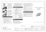
J3
JU1-8
Status LED’s
TB1
TB2
TB3
SW3
SW1
SW2
MCB80 Control Board
3
Specifications
MCB80 Board Size: Height = 5.75”, Width = 8.0”, and Depth = 3.0” (w/RLY80)
Input Power: 24VAC at 1.0 Amp (including RLY80 Relay Board option). There is an onboard 1.6 Amp fuse and power switch. Termination’s for power are at TB3. There must be a
common ground between all the network devices to prevent damaging the network interface
circuitry. The 24VAC RET circuit should be securely connected to earth ground on ALL
MCB80, and the MST200 must also be securely grounded to the same earth ground to prevent
damage to the network circuitry.
Output Power: Terminals are provided on the board for providing power for external sensors
and output relays. A 24VDC terminal is available on TB2 for providing a maximum of 0.2 Amp
if the optional RLY80 Relay board is used, or a maximum of 0.4 Amp if the RLY80 board is
not used, for external 4-20ma sensors/transducers and relays.
Universal Inputs: The MCB80 provides up to eight (8) inputs that may be used as either
analog or digital inputs. Jumpers JU1-8 are provided to select the input configuration. Analog
signals of 0-5VDC or 4-20ma may be connected as well as Thermistor (10K at 77 deg F)
temperature sensors. Alternately, a dry contact closure may be connected between the input
and “IRET”. See the jumper selections described below.
Typical 420ma
Sensor
24VDC
24VDC
RET
AI#1, JU1 = B (4-20ma)
AI#2, JU1 = none (0-5vdc)
Typical
Voltage
Sensor
IRET
Thermistor Pwr
Thermistor
AI#1, JU1 = none (Thermistor)
Typical Analog Inputs
Digital Inputs: If the RLY80 Relay board option is installed, up to eight (8) 24VDC digital
inputs may be connected to TB1 of the RLY80 board. Use good quality contacts in the field
mounted digital sensor, since only a 5ma current is flowing into the Digital Input when the field
switch is closed. Without the optional RLY80 Relay board installed, the Universal inputs must
be used for digital sensors.
Input Switch
AI#1
AI#2, JU2=A
IRET
Typical Digital Input (Universal Input)
AI#3
Digital Outputs: The MCB80 provides up to eight (8) 24VDC “SINKING” transistor digital
outputs for the control of external loads. Each output is capable of “SINKING” (switching to
4
DC RET) loads of a maximum of 50 milliamperes at 24VDC. This is sufficient power to switch
most general purpose 24VDC relays and contactors. If the optional RLY80 Relay board is
installed, output relays and manual AUTO/ON/OFF override switches are provided. The eight
red LED lights labeled 1-8 on the MCB80 board represent the logical state of the eight digital
outputs.
CR1
24VDC
DO#1
Typical Digital Output w/o
RLY80 board
RET
Analog Outputs: The MCB80 provides up to two (2) 4-20ma analog outputs. These outputs
source current for an external transducer. Normally, the external transducer contains either a
250 Ohm or 500 Ohm load resistor which will convert the 20ma maximum output value to
5.0VDC or 10.0VDC respectively.
24VDC
AO#1
250
Typical 420ma
Transducer
RET
Typical Analog Output
Handheld Terminal Port: The RJ11 telephone type connector, J2, is used to connect the
MCB80 to the optional Handheld Terminal. This terminal device allows the user to monitor and
modify the configuration settings of the MCB80. These configuration settings are also
monitored and modified using the Network Master, MST200.
RLY80 Port: The MCB80 is equipped with a ribbon cable connector, J3, that is used to
connect a RLY80 Relay board to the MCB80. This cable provides power and signals to
operate the RLY80 board.
The BD OK Relay: This relay is provided for use as a signal to other equipment that the
microprocessor or memory of the MCB80 has failed. The MST200 Network Master will
independently diagnose a failure due to the failed MCB80 not responding to inquiries on the
Network. This relay’s contacts are rated for 24VAC or 24VDC at 2 Amps maximum.
DIP Switches: Located along one edge of the MCB80 Board are three sets of switches, eight
switches in each set. Switch set, SW1, is used to set the network address and network baud
rate. Switch set, SW2, is used to set the Normally-Open/Normally-Closed action of each of
the digital outputs. Switch set, SW3, is used to set, for each of the digital outputs, whether the
5
corresponding digital input is being used as a “Status” indication of the equipment controlled by
the digital output.
6
Installation
MCB80 Summary of Connections
The terminal strips, connectors and jumpers of the MCB80 board are described below.
TB1, TB2 and TB3 Connections
TB1
1
Function
AI#1
TB2
1
Function
RET (return for 24VDC supply)
2
AI#2
2
RET (return for 24VDC supply)
3
IRET (input return)
3
24VDC Power Supply
4
AI#3
4
24VDC Power Supply
5
AI#4
5
DO#8
6
IRET (input return)
6
DO#7
7
AI#5
7
DO#6
8
AI#6
8
DO#5
9
IRET (input return)
9
DO#4
10
AI#7
10
DO#3
11
AI#8
11
DO#2
12
IRET (input return)
12
DO#1
13
Thermistor Power Supply
14
Thermistor Power Supply
TB3
Function
15
Thermistor Power Supply
1
RET for 24VAC
16
Thermistor Power Supply
2
RET for 24VAC
17
AO#1 (source of 4-20ma current)
3
24VAC power to the board
18
AO#2 (source of 4-20ma current)
4
Common for the “OK” relay
19
24VDC Power Supply
5
NC contact of the “OK” relay
20
Master Panel Override
6
NO contact of the “OK” relay
21
RET
22
Network Signal “A”
23
Network Signal “B”
24
Network Common
Table 1 Terminal Strip Functions
J1 (expansion)
Currently, this connector is not used. It is reserved for future use.
J2 (Handheld Terminal)
Used to connect the ISAC Handheld Terminal for monitoring and modification of board
settings.
J3 (RLY80 board connector)
7
When the optional RLY80 Relay board is used, plug the 20 conductor ribbon cable into this
connector. Note that when the RLY80 Relay board is used, the terminals for Digital Outputs
on TB2 cannot be used, as the operation of the RLY80 board may be interfered with.
Option Jumpers of the MCB80
JU1 - 2-pos jumper for AI#1, A=DI, B=4-20ma, NONE=0-5VDC or Thermistor
JU2 - 2-pos jumper for AI#2, A=DI, B=4-20ma, NONE=0-5VDC or Thermistor
JU3 - 2-pos jumper for AI#3, A=DI, B=4-20ma, NONE=0-5VDC or Thermistor
JU4 - 2-pos jumper for AI#4, A=DI, B=4-20ma, NONE=0-5VDC or Thermistor
JU5 - 2-pos jumper for AI#5, A=DI, B=4-20ma, NONE=0-5VDC or Thermistor
JU6 - 2-pos jumper for AI#6, A=DI, B=4-20ma, NONE=0-5VDC or Thermistor
JU7 - 2-pos jumper for AI#7, A=DI, B=4-20ma, NONE=0-5VDC or Thermistor
JU8 - 2-pos jumper for AI#8, A=DI, B=4-20ma, NONE=0-5VDC or Thermistor
JU10 - MUST BE INSTALLED
Switch set SW1
1 - Network Address switch 1 (see Table 2, below)
2 - Network Address switch 2 (see Table 2, below)
3 - Network Address switch 3 (see Table 2, below)
4 - Network Address switch 4 (see Table 2, below)
5 - Network Address switch 5 (see Table 2, below)
6 - Network Baud Rate, OFF=2400, ON=9600
7 - Network Fail Detect Delay, OFF=60 min, ON=5 min
8 - Digital Output Staging delay (at power up), OFF=2 sec, ON=15 sec
Network Address Settings
Address
1
2
3
4
5
6
7
8
9
10
11
12
13
14
15
16
17
18
19
SW1-1
off
on
off
on
off
on
off
on
off
on
off
on
off
on
off
on
off
on
off
SW1-2
off
off
on
on
off
off
on
on
off
off
on
on
off
off
on
on
off
off
on
SW1-3
off
off
off
off
on
on
on
on
off
off
off
off
on
on
on
on
off
off
off
SW1-4
off
off
off
off
off
off
off
off
on
on
on
on
on
on
on
on
off
off
off
SW1-5
off
off
off
off
off
off
off
off
off
off
off
off
off
off
off
off
on
on
on
8
20
21
22
23
24
25
26
27
28
29
30
31
32
on
off
on
off
on
off
on
off
on
off
on
off
on
on
off
off
on
on
off
off
on
on
off
off
on
on
off
on
on
on
on
off
off
off
off
on
on
on
on
off
off
off
off
off
on
on
on
on
on
on
on
on
on
on
on
on
on
on
on
on
on
on
on
on
on
Table 2, Network Address SW1 Settings
Switch SW2 is used to select the Normally-open/closed setting of each Digital Outputs. A
setting of Normally-open (NO) means that when the MCB80 turns a Digital Output ON, the
output device (relay or other device) ENERGIZES. A setting of Normally-closed (NC) means
the opposite, when the MCB80 turns a Digital Output ON, the output device DEENERGIZES. The same logic applies when the RLY80 board is used, the on-board relays
energize and de-energize in the same way.
Switch set SW2
1 - NO/NC setting for DO#1, OFF=NO,
2 - NO/NC setting for DO#2, OFF=NO,
3 - NO/NC setting for DO#3, OFF=NO,
4 - NO/NC setting for DO#4, OFF=NO,
5 - NO/NC setting for DO#5, OFF=NO,
6 - NO/NC setting for DO#6, OFF=NO,
7 - NO/NC setting for DO#7, OFF=NO,
8 - NO/NC setting for DO#8, OFF=NO,
ON=NC
ON=NC
ON=NC
ON=NC
ON=NC
ON=NC
ON=NC
ON=NC
Switch SW3 is used to select whether the corresponding DI# input is used to monitor the status
of the load connected to the same numbered DO#. If “yes” is selected, the MCB80 monitors
the state of the DI# and if the DI is in the opposite state as the DO#, a “Failure” condition is
sent to the Network Master (MST200) on the next polling cycle. The MCB80 waits for 30
seconds after any change of the output before beginning to monitor the status DI#.
Switch set SW3
1 - Use DI#1 for status of DO#1?
2 - Use DI#2 for status of DO#2?
3 - Use DI#3 for status of DO#3?
4 - Use DI#4 for status of DO#4?
5 - Use DI#5 for status of DO#5?
OFF=no,
OFF=no,
OFF=no,
OFF=no,
OFF=no,
ON=yes
ON=yes
ON=yes
ON=yes
ON=yes
9
6 - Use DI#6 for status of DO#6? OFF=no, ON=yes
7 - Use DI#7 for status of DO#7? OFF=no, ON=yes
8 - Use DI#8 for status of DO#8? OFF=no, ON=yes
10
Operation
The MCB80 is mostly used for remote inputs and outputs of a networked control system. At
ISAC, the Network Master is the MST200 Master. Up to 128 MCB80’s can be connected
to the ISAC Network, 32 board per network channel, 4 network channels on the MST200.
Independent of the Network commands, the MCB80 can perform some functions on it’s own.
The MCB80 “BD OK” light is located between TB2 and TB3. This green colored LED is
normally lit while the MCB80 is powered up and working properly. If the board detects a
problem with it’s microprocessor or memory, this LED will blink and the on-board BD OK
Relay will turn on and off at the same rate. Wiring the output contacts of the BD OK Relay to
an external alarm light will cause it to blink on and off when the board has failed. Since the BD
OK Relay is normally energized, the NO contact will be closed and the NC contact will be
open during normal operation.
When the Master Panel Input is activated (TB1-20), by connecting it to RET through an
external switch, the Digital Outputs will go to a predefined Master Panel Override State and
remain in that state indefinitely. The Master Panel Override States may be programmed using
the MST200’s features or through the use of the Handheld Terminal plugged directly into the
MCB80.
When the Network Master is off-line (not scanning regularly), the MCB80 will wait a delay of 5
minutes or 60 minutes, depending on a setting of SW1, the Digital Outputs will go to a
predefined Master Fail State and remain in that state indefinitely.
When the MCB80 is powered up, it staggers the setting of it’s Digital Outputs with either a 2
second or 15 second delay, depending on a setting of SW1.
Analog outputs may be programmed to control a closed PID algorithm. This PID loop control
function will continue regardless of whether the Network Master is on-line or not. To use this
closed loop PID feature, the corresponding Analog Input to either an Analog Output (4-20ma)
or Digital Output (Pulse width modulated) is used as the control variable measurement input.
See other sources for an explanation of how a PID algorithm works. Input AI#1 is used with
AO#1 or DO#1, input AI#8 is used with DO#8 (only 2 AO’s exist, PID channels 2-8 only use
Pulse Width Modulation).
The Handheld terminal may be used to monitor and change MCB80 settings. This terminal
device may be connected to the MCB80 board via J2 at any time regardless of whether the
MCB80 is powered up or not. Once connected and after a 1 to 12 second delay, the LCD
display of the Handheld terminal will display a Main Menu. A full ASCII keyboard is provided
on the terminal, there are some special function keys that have been specially programmed at
ISAC’s factory to perform needed functions. The “F1” key is used to escape or back out of
11
the current screen without accepting the changes made, if any. The “F5” key is used to move
the cursor from field to field like the function of a TAB key.
MCB80 ITEM NUMBERS USED BY THE MST200 NETWORK MASTER
When defining inputs and outputs located on the MCB80 board in the MST200 Master, each
input, output and information data point is referred to by means of an “ITEM” number. Each
type of input and output has it’s own list of ITEM numbers. For example, when defining the
Status Input #1 of the MCB80 in a MST200 DIGITAL INPUT DEFINITION, the user would
enter “12” as the input number (Item) after specifying the channel# and panel# (board network
address) of the MCB80. The following tables list the MST200 ITEM number for each of the
data points of the MCB80 that can be accessed.
MCB80 data point
Master Panel OVR Input
not used
not used
Universal Input 1 (digital)
Universal Input 2 (digital)
Universal Input 3 (digital)
Universal Input 4 (digital)
Universal Input 5 (digital)
Universal Input 6 (digital)
Universal Input 7 (digital)
Universal Input 8 (digital)
Status Input 1 (RLY80)
Status Input 2 (RLY80)
Status Input 3 (RLY80)
Status Input 4 (RLY80)
Status Input 5 (RLY80)
Status Input 6 (RLY80)
Status Input 7 (RLY80)
Status Input 8 (RLY80)
MST200
ITEM#
1
2
3
4
5
6
7
8
9
10
11
12
13
14
15
16
17
18
19
MCB80 data point
Analog Input 1
Analog Input 2
Analog Input 3
Analog Input 4
Analog Input 5
Analog Input 6
Analog Input 7
Analog Input 8
MST200
ITEM#
1
2
3
4
5
6
7
8
Analog Output 1
Analog Output 2
Analog Output 3
Analog Output 4
Analog Output 5
Analog Output 6
Analog Output 7
Analog Output 8
1
2
3
4
5
6
7
8
Digital Output 1
Digital Output 2
Digital Output 3
Digital Output 4
Digital Output 5
Digital Output 6
Digital Output 7
Digital Output 8
1
2
3
4
5
6
7
8
Table 3, MST200 ITEM numbers
12
MCB80 HANDHELD TERMINAL SCREEN ABBREVIATIONS
The following is a description of each display and the meanings for the abbreviations used.
They are not necessarily listed below in the sequence that the screens may normally be entered.
The heading includes the title shown at the upper left corner of each screen in ‘{}’ marks.
{AI} Analog Input Screen:
1-8 The current value of the Analog Inputs 1-8 expressed
in % of input range.
{DI} Universal Input (as digital data) Screen:
1-8 The current logic state of the 8 Universal Inputs are
displayed as ‘+,-‘ symbols. Note, the digital state
should be ignored for any inputs being used as analog
inputs.
{AO} Analog Output Screen:
1-8 The current analog value sent from the Master to control
analog or PWM type output via PID calculations are
displayed. If a channel is programmed for PID
calculations, then the value will be displayed in the
proper units (ie degF, MA, etc). However, if the
channel is not programmed for PID, the value will be
displayed as a percent of full scale (0-100%).
{STAT} Status input Screen:
9-16 The status input state is displayed by Master numbering
sequence (+,-).
{PID} PID Channel Monitor Screen:
IN
The current value of the corresponding analog input
which is used for control.
SP
Current setpoint used for the channel.
ERR% The percentage error between the setpoint and the
actual analog input measurement expressed as a percent.
UPT The changing timer which times the update of the PID
calculations and the output changes.
INT The changing timer which times the PID Integral
calculations.
TGT% The theoretical % output when the ERR%=0. This changes
when an Integral calculation is done. For a well designed
system, this value should stay close to 50%. If this
value drifts below 20% or above 80% it could mean that
13
the control system may not have enough control range
to maintain the setpoint properly.
OUT This is the analog output value that is being used.
To manually change the output value, the AO Screen
value must be changed.
{PID1} PID Configuration Screen #1:
CH Shows the current channel being configured. Changing
this value allows all 8 channels to be programmed.
DDC Direct digital control flag, if set to ‘N’ (no),
the corresponding digital output may be used for normal
ON/OFF control.
UDT Update time of PID control loop (sec).
LLM% Low limit of the analog (or pulse width) output.
HLM% High limit of the analog (or pulse width) output.
DSP Default setpoint used in the event that a valid
setpoint is not received from the Master.
OSP Override setpoint used when a status input is configured
for override operation of a PID channel and the
input is activated.
HLDSP Current setpoint is held in the event of a network
failure enable (Y/N).
{PID2} PID Configuration Screen #2:
CH Shows the current channel being configured. Changing
this value allows all 8 channels to be programmed.
CLSLP Closed loop enable (Y/N). If this is set to ‘N’
then the setpoint is interpreted as a percent and the
output is controlled as a strictly proportional ‘P’
only control. The Integral and Derivative influence
are disabled. The control is done on a percent basis.
PB% Proportional band. The proportional band is expressed
as a percent of the total input range.
ITM Integral update interval (sec).
DR% Derivative rate percent. This is the percent error
detected by the system at which the derivative calculation
will add a correction.
T
Type of DDC output Pulse or Analog (P/A). Note that
there are only 2 true analog outputs on the MCB80
so only channels 1 and 2 may be true analog, the
other channels may be pulse type only.
D
Direction of the control output (I/D). If an ‘I’
is entered, the control expects that the output
14
current will have to increase in order to make the
input value being monitored increase in value. Enter
‘D’ for the opposite effect.
R
Range of analog output (only affects true analog
outputs). Enter ‘0’ for 0-20 milliamperes and
‘4’ for 4-20 milliamperes.
MNPW Minimum pulse width. For use with pulse width output
channels only. Defines the shortest possible pulse
(usually 0, seconds).
MXPW Maximum pulse width. For use with pulse width output
channels only. Defines the maximum pulse possible
(1-32 seconds).
{PID3} PID Configuration Screen #3:
CH Shows the current channel being configured. Changing
this value allows all 8 channels to be programmed.
(minimum and maximum of the following is entered)
OUT The scaling limits for the output in units of the
process such as PSI, MA, or %. This scaled value
appears in the PID monitoring screen and is sent back
to the Master via the network.
IN
The scaling limits for the input channel used for PID
calculations. This is the input value expected when
the input terminal voltage is at 0 and 5VDC.
{FAIL} Configuration Network Fail State for Outputs:
1-8 Each digital output channel may be programmed to
be forced to a defined state in the case that the
Trinet network does not operate for more than 2 hours.
The choices are ‘O’=on, ‘F’=off and ‘N’=no change.
{MST} Configuration of Master Override State for Outputs:
1-8 Each digital output channel may be programmed to
be forced to a defined state in the case that the
Master digital input is activated.
The choices are ‘O’=on or ‘F’=off.
{UNIV} Configuration of Analog Sensor Type:
1-8 Each Universal input that is configured (hardware)
for use as an analog input may be set for a linear
sensor type or for a Precon 10K Thermistor (which
requires linearization in the MCB80).
The choices are ‘L’=linear or ‘T’=Thermistor.
15
{STS} Configuration of Status Inputs:
1-8 Each digital status input may be programmed to act
as a direct override, general purpose digital input
or as a true status for the corresponding digital
output.
The choices are ‘G’=general purpose, ‘S’=status input,
or ‘O’=direct override.
{MODE} Configuration of Override Mode for Outputs:
1-8 Each digital status input may be programmed to act
as a direct override on the corresponding digital
output. The choices are 0=disable, 1-8=30 min interval
timer or 14=sweep off operation.
16