1
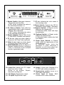
1. Reader Switch: Alternates between
Time Code and User Bits.
In SET mode, increases the value of
the selected parameter (+).
7. CF LED: Indicates the color status of
the incoming code.
2. Fix Video ø Switch: Time shifts the
regenerated code to align it properly
with the video reference.
In SET mode, decreases the value
of the selected parameter (-).
9. Bypass Switch: In Repair mode,
bypasses the regenerator;
In Generate mode, starts and stops
the generator.
3. Reader display: Reads Time Code
or User Bits & indicates video phase.
4. TC In LED: Lights up when signal is
present at the Time Code input jack.
5. Video In LED: Lights up when signal
is present at the Video input jack.
6. 24/25/30ND/30D LED’s: In Repair &
Bypass, indicate format of incoming
code; in Generate mode indicate
format of generated code.
TIME CODE
OUTPUT
INPUT
Level Out
8. Mode Switch: Selects the SR-3’s
operations mode: Repair / Generate.
10. Flywheel Switch: In Repair mode,
selects the flywheel time;
In Generate mode, selects the field
to be edited.
11. Video Sync Switch: In Repair
mode, locks the regenerator to ext
video reference;
In Generate mode, locks the
generator to video reference if
available or pulls down rate if ext.
video is not present (i.e. 29.97)
POWER
6-9VDC
@ 500ma
VIDEO
Off
75Ω
Termination
LOOP
IN
12. Level Out: Adjusts the TC output
level from off to +12db.
Active in all modes: Repair,
Generate and Bypass
15. Power: 2.5mm jack. Requires 6 to
12 VDC with center pin positive.
13. TC Output: Regenerator output.
17. Video Input & Loop: BNC
connectors for video reference.
14. TC Input: Regenerator input
16. Termination switch: turns on a
75Ω video termination.